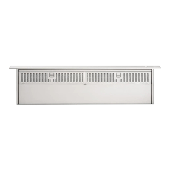
DCS DD-30SS Installation Manual
The professional downdraft
Hide thumbs
Also See for DD-30SS:
- Use and care manual (24 pages) ,
- Use and care manual (10 pages) ,
- Use and care manual (10 pages)
Table of Contents
Advertisement
Available languages
Available languages
Quick Links
Advertisement
Chapters
Table of Contents

Subscribe to Our Youtube Channel
Related Manuals for DCS DD-30SS


Summary of Contents for DCS DD-30SS
- Page 1 THE PROFESSIONAL DOWNDRAFT Installation Guide MODELS DD-36SS DD-30SS...
-
Page 2: A Message To Our Customers
A MESSAGE TO OUR CUSTOMERS Thank you for selecting this DCS Downdraft Vent System. Because of its unique features, we have developed this Installation Guide. It contains valuable information on how to properly install your new Downdraft Vent System for years of safe and enjoyable cooking. -
Page 3: Table Of Contents
SAFETY PRACTICES & PRECAUTIONS ...3 PLANNING THE INSTALLATION...4 Venting Requirements...4 Electrical Requirements ...4 SPECIFICATIONS ...5 INSTALLATION INSTRUCTIONS ...6-11 Tools Needed ...6 Plan The Ductwork...6 Calculate the Duct Run Length ...6 Plan And Make The Cutout ...7 Installing The Downdraft Vent ...8-11 WIRING DIAGRAM ...12 HOW TO OBTAIN SERVICE ...13 WARRANTY ...14-15... -
Page 4: Safety Practices & Precautions
SAFETY PRACTICES & PRECAUTIONS WARNING: ALL WALL AND FLOOR OPENINGS WHERE THE Downdraft IS INSTALLED MUST BE SEALED. Consult the cooktop installation instructions given by the manufacturer before making any cutouts. MOBILE HOME INSTALLATION - The installation of this Downdraft must conform to the Manufactured Home Construction and Safety Standards, Title 24 CFR, Part 3280 (formerly Federal Standard for Mobile Home Construction and Safety, Title 24, HUD, Part 280). -
Page 5: Planning The Installation
VENTING REQUIREMENTS Determine which venting method is best for your application. Ductwork can extend either through the wall or the roof. The length of the ductwork and the number of elbows should be kept to a mini- mum to provide efficient performance. The size of the ductwork should be uniform. Do not install two elbows together. -
Page 6: Specifications
SPECIFICATIONS 8-1/4" 27" for 30" model 33" for 36" model 16" 3-1/4" x 10" 16" 9-3/8" Fig. 01 Downdraft Dimensions 4-1/8" 1/2 " min. 17-3/16" 3/8" 3-1/4" 4-1/8" 3/8" 10" 4-1/8" 1/2" min. FIG.02 Ductwork Cutout Dimensions 30" 36" 1-1/2" 26-1/8"... -
Page 7: Installation Instructions
1 Wall or Roof Cap All Metal Ductwork PLAN THE DUCTWORK The DCS 36” and 30” downdraft vent system can be ducted in four different directions; down, left, right or back using a 3-1/4" X 10" rectangular vent. Fig. 03 illustrates venting options. -
Page 8: Plan And Make The Cutout
It is recommended that the installer draw the cooktop and downdraft cutouts on the countertop before making any cutouts to avoid mistakes. Fig. 06 shows the cutout dimensions for DCS CT-365 and CT-304 and for all other cooktops see Fig. 06a (page 8). Fig. 07 shows the tolerances between the cooktop and the downdraft. -
Page 9: Installing The Downdraft Vent
DROP-IN COOKTOP (MISC. BRAND) CUT-OUT DIMENSIONS (WITH DOWNDRAFT) 1/2" Min. Rear of Downdraft Cutout Rear Edge of Cooktop 1-3/4" 5" Min. clearance to combustible surface INSTALLING DOWNDRAFT VENT 1) Remove the unit from the carton and place on a flat surface for assembly. - Page 10 5) Remove the unit from the cabinet. Drill starter holes in the cabinet floor for the leg screws. 6) DCS downdrafts are shipped from the factory ready to vent in the down position. If you need to vent back, left or right, then the blower must be reposi- tioned.
- Page 11 INSTALLING DOWNDRAFT (continued) the downdraft. The square metal frame must be attached to the mouth of the blower. The exhaust knockout on the rear must be removed. A metal plate and two screws are supplied in the hardware package to cover the unused exhaust exit. CAUTION: Make sure that the wiring cable connecting the blower to the field wiring compartment remains securely attached under the two cable clamps.
- Page 12 INSTALLATION INSTRUCTIONS INSTALLING DOWNDRAFT (continued) 13) Connect the ductwork to the Backdraft damper. Seal all joints with duct tape and vent to the outside of the home. 14) Install the cooktop according to the cooktop manufacturer's instructions. Check to make sure that the rear edge of the cooktop overlaps the front edge of the downdraft by 3/8".
-
Page 13: Wiring Diagram
WIRING DIAGRAM PUSH BUTTON N.O. GEAR MOTOR 11 UF BLOWER MOTOR 8/50K-A120 SWITCH FAN N.O. SWITCH FILTER N.O. -
Page 14: How To Obtain Service
3) Are the grease filters properly installed? 4) Will the unit go up/down and the motor control is ON? For warranty service, contact DCS Customer Care at (888) 281-5698. Before you call, please have the following information ready: Model Number... -
Page 15: Warranty
LIMITED WARRANTY When you purchase a new DCS Ventilation Product for personal or consumer use you automatically receive a One year Limited Warranty covering parts and labor for the entire product, and a Five year Limited Warranty on the switches and motor (parts only) for servicing within the 48 mainland United States, Hawaii,Washington D.C and Canada. -
Page 16: How To Get Service
Please read your User Guide. If you then have any questions about operating the Product, need the name of your local DCS Authorized Service Agent, or believe the Product is defective and wish service under this Limited Warranty, please contact your dealer or call us at: TOLL FREE 1-888-281 5698 or contact us through our web site: www.dcsappliances.com. - Page 17 NOTES...
- Page 18 HOTTE PROFESSIONNELLE Manuel d'installation MODELES DD-36SS DD-30SS...
- Page 19 A L’INTENTION DE NOS CLIENTS Nous vous remercions d’avoir choisi cette hotte à évacuation à tirage par le bas de DCS. Nous avons conçu ce Manuel d’installation pour expliquer ses fonctions uniques. Il contient des informations extrêmement utiles sur la façon d’installer correctement votre nouvel appareil. Vous pourrez ainsi en profiter pendant des années en toute sécurité.
- Page 20 TABLE DES MATIERES MESURES DE SECURITE ET DE PRECAUTION...3 PLANIFICATION DE L’INSTALLATION...4 Exigences de ventilation ........................4 Exigences électriques .
-
Page 21: Mesures De Securite Et De Precaution
MESURES DE SECURITE ET DE PRECAUTION AVERTISSEMENT : TOUTES LES OUVERTURES MURALES ET DE PLANCHER OÙ EST INSTALLÉE LA HOTTE DOIVENT ÊTRE FERMÉES. Consultez les instructions de montage de la table de cuisson fournies par le fabricant avant d’effectuer les découpes. INSTALLATION DANS UNE MAISON MOBILE – L’installation de cette hotte doit respecter les normes Manufactured Home Construction and Safety Standards, Titre 24 CFR, Section 3280 (ancienne appellation : Federal Standard for Mobile Home Construction and Safety, Titre 24, HUD, Section 280). -
Page 22: Planification De L'installation
PLANIFICATION DE L’INSTALLATION EXIGENCES DE VENTILATION Déterminez la meilleure méthode de ventilation pour votre application. Les conduits peuvent passer par le mur ou le toit. Leur longueur et le nombre de coudes doivent être réduits à un minimum afin d’assurer un bon rendement. Les dimensions des conduits doivent être uniformes. Ne juxtaposez pas deux coudes. -
Page 23: Caracteristiques
CARACTERISTIQUES 10.95 cm (8-1/4 po) 68.58 cm (27 po) (30 po model) 83.82 cm (33 po) (36 po model) 40.64 cm (16 po) 8.25 cm x 25.4 cm (3-1/4 po x 10 po) 40.64 cm (16 po) Fig. 01 Cotes de la hotte .95 cm 43.66 cm (3/8... -
Page 24: Instructions De Montage
Conduits métalliques PLANIFIEZ LE SYSTÈME DE CONDUITS L’évacuation de la hotte 36 po et 30 po de DCS peut être dirigée vers quatre sens différents : vers le bas, la gauche, la droite ou l’arrière à l’aide d’un évent d’aération rectangulaire de 8.26 cm (3-1/4 po) X 25.4 cm (10 po). -
Page 25: Planifiez Et Effectuez La Découpe
La Figure 06 montre les dimensions de découpe du modèle DCS CT-365 et CT-304. Reportez-vous à la Fig. 06a (Page 8) pour toutes les autres tables de cuisson. La Fig. 07 indique les tolérances entre la table de cuisson et la hotte. Celles-ci doivent être respectées pour assurer une bonne installation. -
Page 26: Installation De La Hotte
INSTRUCTIONS DE MONTAGE TABLE DE CUISSON SUSPENDUE (MARQUE DIVERSE) DIMENSIONS DE DÉCOUPE (AVEC HOTTE) 1.3 cm (1/2 po) min. Arrière de la découpe de la hotte Bordure arrière *14.45 cm (1-3/4 po) de la table de cuisson Écart de 12.7 cm (5 po) min. - Page 27 5) Retirez l’appareil de l’armoire. Percez les trous-guides dans le fond de l’armoire pour les vis des pieds. 6) Les hottes DCS sont livrées pour une évacuation par le bas. Si vous désirez que l’évacuation se fasse par l’arrière, la gauche ou la droite, vous devez repositionner le ventilateur.
- Page 28 INSTRUCTIONS DE MONTAGE INSTALLATION DE LA HOTTE (suite) MISE EN GARDE : Assurez-vous que le câble connectant le ventilateur au compartiment de câblage demeure bien fixé sous les deux serres-câble. 7) Fixez le registre antirefoulement. 8) Retirez le couvercle du compartiment de câblage et déterminez le sens d’acheminement du câblage de l’appareil vers la boîte de câblage, puis défoncez le trou de câblage.
- Page 29 INSTALLATION DE LA HOTTE (suite) 13) Connectez le système de conduits au registre antirefoulement. Scellez tous les joints à l'aide de ruban pour conduits et dirigez l’évacuation vers l’extérieur de la maison. 14) Installez la table de cuisson conformément aux instructions du fabricant. Assurez-vous que le bord arrière de la table de cuisson est superposé...
-
Page 30: Schema De Cablage
WIRING DIAGRAM BOUTON-POUSSOIR N.O. MOTEUR À ENGRENAGES 11 UF MOTEUR DU VENTILATEUR 8/50K-A120 INTERRUPTEUR DU VENTILATEUR N. O. INTERRUPTEUR DU VENTILATEUR N. O. -
Page 31: Pour L'obtention De Service
4) L'appareil se déplacera-t-il vers le haut/bas alors que la commande de moteur est activée? Pour le service sous garantie, contactez le centre DCS agréé le plus proche au (888) 281-5698. Avant d'appeler, veuillez avoir les informations suivantes à portée de main : Numéro de modèle... -
Page 32: Garantie
Cette garantie s'applique à l'acheteur initial et à tous les propriétaires successifs du produit dans la mesure où il s'agit d'un produit acheté pour une utilisation à domicile normale. Tout service couvert par cette garantie limitée sera assuré par Fisher & Paykel ou son agent de service DCS agréé durant les heures d'ouverture normales. - Page 33 Veuillez consulter le guide de l'utilisateur. Si vous avez des questions concernant l'utilisation du produit, que vous cherchez le nom de l'agent de service DCS agréé local ou que pensez que le produit est défectueux et désirez le faire réparer dans le cadre de cette garantie limitée, veuillez contacter votre distributeur ou nous appeler au numéro suivant :...
- Page 34 GARANTIE AUCUNE AUTRE GARANTIE Cette garantie limitée constitue l'accord entier et exclusif entre vous et Fisher & Paykel en ce qui concerne tout défaut du produit. Aucun de nos employés (ou agents de service agréés) n'est autorisé à apporter des ajouts ou des modifications à cette garantie limitée. Garant : Fisher &...
- Page 35 NOTES...
- Page 36 NOTES...
- Page 37 NOTES...
- Page 38 5900 Skylab Road, Huntington Beach, CA 92647 Customer Care: 888.281.5698 Fax: 714.372.7003 www.dcsappliances.com As product improvement is an ongoing process at DCS, we reserve the right to change specifications or design without notice. DCS améliore constamment ses produits et se réserve le droit de modifier les spécifications ou la conception de...
Need help?
Do you have a question about the DD-30SS and is the answer not in the manual?
Questions and answers