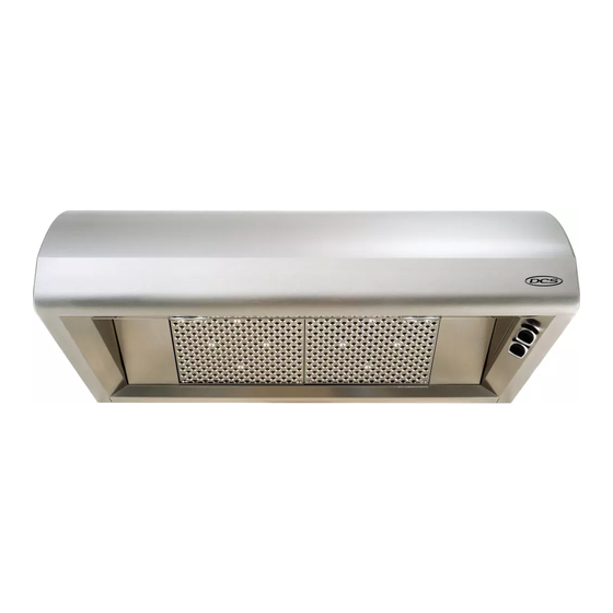
DCS EH-36SS Use And Installation Manual
The professional euro hood
Hide thumbs
Also See for EH-36SS:
- Installation manual (16 pages) ,
- Use and care manual (11 pages) ,
- Installation manual (14 pages)
Subscribe to Our Youtube Channel
Summary of Contents for DCS EH-36SS
- Page 1 Dynamic Cooking Systems, Inc. THE PROFESSIONAL EURO HOOD Use and Installation Guide Models: EH-30SS EH-36SS...
-
Page 2: A Message T O Our Customers
A Message T o Our Customers Thank you for selecting this DCS Updraft Euro Hood. Because of its unique features, we have developed this Use and Installation Guide. It contains valuable information on how to properly operate and maintain your new Updraft Euro Hood for years of safe and enjoyable cooking. -
Page 3: Table Of Contents
T able Of Contents SAFETY PRACTICES & PRECAUTIONS SPECIFICATIONS ...4 PLANNING THE INSTALLATION INSTALLATION INSTRUCTIONS Tools Needed ...6 Standard Installation Dimensions ...7 Ceiling Height Variances...8 Calculate Duct Run Length...9 Wall Preparation...9-10 Installing Euro Hood...10-11 Optional Ductless Installation Kits ...11 USE AND CARE ...12 WIRING DIAGRAM ...13... -
Page 4: Safety Practices & Precautions
Safety Practices & Precautions This euro hood system is designed to remove smoke, cooking vapors and odors from the cooktop area. WARNING: ALL WALL AND FLOOR OPENINGS WHERE THE EURO HOOD IS INSTALLED MUST BE SEALED. Consult the cooktop or range installation instructions given by the manufacturer before making any cutouts. -
Page 5: Specifications
Specifications 14 7/8" 9 7/16" 29 7/8" - 30" Hood 35 7/8" - 36" Hood 1 1 / 1 6 " 4" 4 5/16" 1 1 / 1 6 " 4" 4 5/16" 7 1/2" 8 3 / 4 " 20 7/8"... -
Page 6: Planning The Installation
Planning The Installation VENTING REQUIREMENTS Determine which venting method is best for your application. Ductwork can extend either through the wall or the roof. The length of the ductwork and the number of elbows should be kept to a mini- mum to provide efficient performance. -
Page 7: Installation Instructions
Installation Inst ructions TOOLS NEEDED FOR INSTALLATION • Saber Saw or Jig Saw • Drill • 1 1/4 Wood Drill Bit • Pliers • Phillips Screwdriver • Flat Blade Screwdriver • Wire Stripper or Utility Knife • Metal Snips • Measuring Tape or Ruler •... -
Page 8: Standard Installation Dimensions
Installation Instructions 10 5/16" 30" or 36" 30" cabinet 36" base... -
Page 9: Ceiling Height Variances
Installation Instructions min 21 7/8" max 40" 10 5/16" 30" 36" Upper Chimney Cover Lower Chimney Cover 19 1/2" Max. = 9' 8 5/16" Min. = 8' 2 3/16" cabinet base (116 5/16" 3/16"... -
Page 10: Calculate Duct Run Length
Installation Inst ructions CALCULATE THE DUCT RUN LENGTH The duct run should not exceed 35 feet if ducted six inch (6”) round ductwork. Calculate the length of the ductwork by adding the equivalent feet in fig. 06 for each piece of duct in the system an example is given in fig. -
Page 11: Installing Euro Hood
Installation Inst ructions 5) Determine and make all necessary cuts in the wall for the ductwork. Each euro hood is shipped from the factory vented through the top. In order to vent to the rear, ductwork must run first vertical then elbow to the back. The dimensions for the duct openings are given in Fig. 02. Install all ductwork before installing the euro hood. -
Page 12: Optional Ductless Installation Kits
Installation Instructions 7) The brackets shown in Fig. 08 are also used to adjust the level of the canopy. Using a Phillips screwdriver, rotate the screw V2 to adjust the level of the canopy. 8) Connect the Power Supply Cable to the euro hood. Attach the White lead of the power supply to the White lead of the euro hood with a twist-on type wire connector. -
Page 13: Use And Care
Use & Care In formation CONTROL PANEL The control panel is located on the right-hand side under the canopy. LIGHT ON/OFF SWITCH ( A ) On/Off switch for the halogen light. Move the switch to "1" to turn the light ON and to "0" to turn it OFF. -
Page 14: Wiring Diagram
Wiring Diagram 30” & 36” Hoods... -
Page 15: How To Obtain Service
Model Number, Serial Number, and date of installation, and a brief description of the problem. If you need assistance in locating the authorized service agency in your area please contact our DCS Consumer Service Department for an authorized service agent near you, our number is (888) 281-5698. -
Page 16: Length Of Warranty
DCS to be defective. Replacement will be F.O.B. DCS, and DCS will not be liable for any transportation costs, labor costs, or export duties. This warranty shall not apply, nor can we assume responsibility for damage that might result from failure to follow manufactures instructions or local codes, where the appliance has been tampered with or altered in anyway or which, in our judgement, has been subjected to misuse, negligence, or accident. - Page 17 Notes...
- Page 18 5800 Skylab Road, Huntington Beach, CA. 92647 Tel: (714) 372-7000 Fax: (714) 372-7001 Parts/Customer Service (888) 281-5698 www.dcsappliances.com As product improvement is an ongoing process at DCS, we reserve the right to change specifications or design without notice. Part No. 17386 Rev. A...


Need help?
Do you have a question about the EH-36SS and is the answer not in the manual?
Questions and answers