Table of Contents
Advertisement
Operator's
Manual
9 Amp
71/4-in. Compound
with
Laser Trac TM
Model No.
320.21195
Miter Saw
z_CAUTION:
Read, understand
and
follow all Safety Rules and Operating
instructions
in this Manual before using
this product
• WARRANTY
• SAFETY
• UNPACKING
• ADJUSTMENT
. OPERATION
• MAINTENANCE
• ESPAI_O L
Sears, Roebuck and Co., Hoffman Estates, IL 60179 U.S.A_
Visit our Craftsman web site: www.sears.comtcraftsman
Advertisement
Table of Contents

Related Manuals for Craftsman 320.21195


Summary of Contents for Craftsman 320.21195
- Page 1 • UNPACKING • ADJUSTMENT follow all Safety Rules and Operating . OPERATION instructions in this Manual before using • MAINTENANCE this product • ESPAI_O L Sears, Roebuck and Co., Hoffman Estates, IL 60179 U.S.A_ Visit our Craftsman web site: www.sears.comtcraftsman...
-
Page 2: One Year Fullwarranty
Page Repair Parts ................. Pages 40-42 Sears Repair Parts Phone Numbers ......Back Cover CRAFTSMAN TOOL YEAR FULLWARRANTY If this Craftsman too! fails to give complete satisfaction within one year from the date of purchase, return it to any Sears... -
Page 3: Symbol Meaning
The purpose of safety symbols is to attract your attention to possible dangers The safety symbols, and the explanations with them, deserve your careful attention and understanding. The symbol warnings DO NOT by lhemselves eliminate any danger The instruclions and warnings they give are no substitutes for proper accident prevention measures this manual, Including all safety alert symbols such as "DANGER",... - Page 4 manual before ustng the miter sew Failure to foliow all Instructions result tn hazardous radiation exposure, electric shock, fire andtor serious [ _WARNING: BE SURE to read and understand alt instructions In this personal Injury. SAFETY PRECAUTIONS FOR LASERS This miter saw has a built-in laser Fight.The laser is a Ciass Ilia and emHs output power of a maximum 2 5mW and 635-665nm wavelenglhs...
- Page 5 SAFETY PRECAUTIONS FOR LASERS conL 7 DO NOT attempt to modify the performance of this laser device in any way This may result in a dangerous exposure to laser radiation, 8 ALWAYS use only the accessories that are recommended by Sears for use with th_s product,.
- Page 6 PERSONAL SAFETY eont, 8 ALWAYS SECURE YOUR W ORK° Use clamps or a vise to hold work when practical It is safer than using your hand and frees both hands to operate tool g USE SAFETY EQUIPMENT, Always wear eye protection, Dust mask, non-skid safety shoes, hard hat, or hearing protection must be used for appropriate...
- Page 7 ELECTRICAL SAFETY z& WARNING: Do not permit fingers to touch the terminal or plug when Installing or removing the plug from an outleL 1 Double insulated tools are equipped w_th a polarized plug (one blade is wider than the other)_Thls plug will fit in a polarized outlet only one way_ If the plug does not fit fully in the...
-
Page 8: Extension Cords
EXTENSION CORDS Use a proper extension cord. ONLY use cords listed by Underwriters Laboratories (UL) Other extension cords can cause a drop in line voltage, resulting in a loss of power and overheating of tool For this tool an AWG (American Wire Gauge) size of a least 14-gauge recommended for an extension cord of 25- ft. -
Page 9: Service Safety
SERVICE SAFETY 1 tf any part of this saw Is missing or should break, bend, or fall In any way; or should any electrical component fall to perform properly: SHUT OFF the power switch and remove the saw plug from the power source and have the missing, damaged or failed parts replaced BEFORE resuming operation 2 Tool service must be performed only at a Sears Parts and Repair... - Page 10 SAFETY RULES FOR MITER SAWS cOnto 13, ONLY USE the correct blades° Use the rlght blade size, style and cutting speed tor the material and the type or cut, DO NOT use biades with Incorrect size holes NEVER use blade washers or blade bolts that are detective or incorrect maximum blade capacity for this saw is 7V4-inehes 14 ALWAYS keep blades...
- Page 11 SAFETY RULES FOR MITER SAWS conL WARNING: Some dust particles created by power sandlng_ sawing, grinding, drilling and other construction jobs contain chemicals known cause cancer, birth defects or other reproductive harm. Some examples of these chemicals are: • Lead from lead-based paints.
- Page 12 Arbor The revolving shaft on whfch a b_ade or cutting tool is mounted, Arbor Lock Allows the user to stop blade from rotating while tightening or loosening the arbor screw during blade replacement or removaf Revolutlons Per Minute (RPM) The number of turns completed by a spinning object in one minute No Hands Zone The area between the marked lines on the left and right sfde of the miter table base This zone is identified by no hands zone symbols inside the marked lines on the...
- Page 13 Chamfer Cut A cut removtng a wedge from a block of wood so the end (or part of the end} is angled at other than 90 _' Ripping or Rip Cut A cutting operation along the length of the workpiece Freehand Performing a cut without using a fence, miter gauge, fixture, work clamp, or other...
- Page 14 If any of the items t[sled are missing, or any breakage or damage has occurred, return the saw to your nearest Sears store or Craftsman ou[le| lo have lhe saw replaced /kWARNING: If any parts are broken or missing,...
- Page 15 4 Includes two, Craftsman ®, 7-1/4qn. carbide-tipped, steel blades; a 24qooth blade for rapid cutting, and a 60-tooth blade for smooth, finish cutting, Both blades are suitable for cutting wood and wood-like materials 5/8-in arbor.
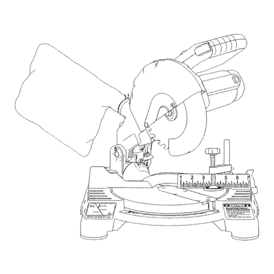
- Page 16 KNOWYOUR MITER SAW (Flg. la and 1b) cont_ Fig. I a \ Arbor Lock Butlon Lower Btada Guard Hold Down Throat Miter Plale Ang!e Miler No-Hands Indicator Table Zone Symbol Laser Caution Label Mounting HO_aS...
- Page 17 KNOWYOUR MITER SAW (Fig, ta and 1b) cool Fig.Ib L_ar On loll Switch On I0[! Trigger 8wilch Dust Ejecllon Purl Meier Housing Mtter LacNng Lever. Fence Locking Bolt Supply power 120V, 6OHz Typeo[ Maximum Angle Selting Thickness Width Rated current Miter Bevel No,,!oad, s peed-...
- Page 18 KNOW YOUR MITER SAW (Fig,, la and lb) cent. Laser On/Off Switch To turn on laser, push the laser switch to "On" On/Off Trigger Switch and Safety Lock-Off Button To turn on saw, push safety lock button in with thumb whiSe squeezing the On/Off Trigger Switch located under the handle (Fig, lb) To shut off saw, simply release both,...
- Page 19 MOUNTING tvltTER SAW TO WORK SURFACE (Fig. 2 and 2a) To prevent your miter saw from sliding, saw must be permanently mounted to a firm, stable supporting surface, such as a workbench or piece of plywood i_.,_._. Four bolt holes have been provided in the saw base (one in each corner) for mounting purposes.
- Page 20 SQUARINGTHE BLADETO '_' " _&_ THE FENCE (Fig. 4) Fig. 4 unplug your saw could result in accidental starting causing serious njury, I Set the bevel and miter angles to 0 _' degrees, 2 Lower and lock the saw arm into _i._._'_ '=4:_ the "DOWN"...
- Page 21 SQUARING THE SLA DE TO THE MITERTABLE 0" Bevel, 0° Miter Fig. 6 (Fig. 6) unplug your saw could result in accidental starting causing Z_ WARNING: Failure to serious Injury. t Set the bevel and miler angle scales to 0_and lock in place 2 Lower and lock lhe saw arm inie the "DOWN"...
- Page 22 THROAT PLATE SLOT (Fig, 7) The th;roat plate was cut (slotted) at the factory' for a 0= bevel/miter The first cut you wifl make with the saw will be to increase this slot in the throat plate by setting the bevel scale to 45 °, locking the bevel lock knob into position and cutting into the throat piate, increasing the width of the sIot...
-
Page 23: Depth Stop Adjustment
ADJUSTtNGTHE BLADETOTHE MITER TABLE 45 _Bevel, 0"MITER (F}g_ 8)conL 7 Once t he angle i sset, t ighten the lock nut w ith the wrench while h olding the set screw i nplace w ith the hex key 8 Lock t he bevel knob BEVEL ANGLE INDICATOR ADJUSTMENT (Fig. - Page 24 Depth Stop Adjustments cent (FIg-lO) t. Unplug the saw. unplug your saw could result accidental starting causing I _WARNING: Failure to serious Injury, 2 To adjust the depth stop use two 8ram wrenches (sold separately) Loosen the lock nut tocated at the rear of the miter saw arm (Fig 10) 3 To lower the blade, adjust the hex bo!l by turning it clockwise...
- Page 25 HOWTO USETHE LASER TRAC FEATURE (Fig. 11) I, Mark your workpiece with a pencit line at the point to be cut. 2 SIide the Laser Trac switch "On" to activate the "bright red laser line" 3 Align the "red laser line" to touch the right edge of your pencil t{ne on the workptece Fig.
-
Page 26: Clamping Wide Workpieces
A WARNING: When using the hold down clamp included or a C-clamp (sold separately) to secure the workplace, clamp the workplace on one side of the blade ONLY.The workplace MUST remain unclamped on the other sfde of the blade to prevent the blade from binding in the workpieceo The workplace... - Page 27 CROSSCUTTING (Fig° 13 and 14) ; .."_---- ..A crosscut is a out made across the _"_ 'L'I_._..._' _ _ .,,__ grain of the workpiece. A straight _-. _ _"L_ , f_l'l_'[},_) crosscut is a cut made with the miter LJ _ table set in the 0 °...
- Page 28 CROSSCUTTING cont. (Ffg, 13 and I4) Z_ WARNING: To avoid serious personal injury, ALWAYS keep your hands outside the "no hands zone", as marked on the saw table, which is at least 3 inches from the blade.. Also, NEVER perform any cutting operation "freehand"...
- Page 29 BEVEL CUTTING conto (flg, 15) 3. Release the saw arm by pulttng out the locking pin, 4 To make a bevel cut, loosen the bevel lock knob (Fig lb) by turning the knob counterclockwise 5 Tilt the saw arm to the desired bevel angle as shown on the bevel scale. The blade can be positioned at any angle, from a 90 °...
-
Page 30: Cutting Base Molding
CUTTING BASE MOLDING (Fig_ 16) FIg_ Mold{ng lying flat or, miler labia Base moldings and many other moldings (bale:re clamping) can be cut on a miter saw. The setup of the saw depends on base molding characteristics FenctJ and applications, as shown Perform practice Miter at O',... - Page 31 COMPOUND MITER CUTTING cent. (FIg_ 17) It may take several settings to obtain the desired cut. The first angle setting should be checked after setting the second angle, since adjusting the second angle affects the first. Once the two correct settings for a particular cut have been obtained, ALWAYS make a test cut in scrap material BEFORE making a finish cut in good material To Make a Compound Mtter Cut with your Miter Saw...
- Page 32 COMPOUND MITER CUTTING conL (Fig, 17) /k WARNING: To avoid serious persona{ in)ury, ALWAYS keep your hands outside the "no hands zone", as marked on the sew table, which is at least 3 Inches from the blade Also, NEVER perform any cutting operation "freehand"...
- Page 33 CUTTING COMPOUND MITERS canto *PITCH NUMBER OF SIDES OF StDE M-29 84° M-22 62_ M-t8 32 ° M-1544 _ M-t336 ° M-1t.79 ° M.1056 _ 8_35.40= B- 28.78° B-24.t8 _' B_20.82_ B-!8.27 '_ B_16.27 o B_14,68 ° ..M-26.57° M-1996 _ M-1610 n M-1354 ° M-1170 °...
-
Page 34: Cutting Crown Molding
CUTTING CROWN MOLDING cont. (Fig. 18) The settings in the table below can be used for cutting all standard (U S.) crown molding with 52"_and 38 ° spring angles The crown molding is placed flat on the miter table, using the compound features of your miter saw Always use the hold down clamp, and place tape on the area being clamped to avoid... - Page 35 CUTTING WARPED MATERIAL (Flgo 19 and 20) Z_WARNING: To avoid kickback and to avoid serious personal Injury NEVER position the concave side of bowed or warped material against the fence, When cutting warped material, BE CERTAIN that the mateda[ to be cut is positioned on the miter table with the convex side against the fence, as shown (Fig.
-
Page 36: Routine Maintenance
ROUTINE MAINTENANCE z:_WARNING: DO NOT at any time let brake fluids, gasoline, petroleum- based products, penetrating oils, etc.. come In contact with plastic parts, Chemicals can damage, weaken or destroy plastic, which may result serlous personal injury. Periodic maintenance allows for tong life and trouble4ree operation A cleaning, lubrication and maintenance schedule... - Page 37 CHANGING THE BLADE cont_ ( see Fig. 2 1) 8 Take t he new blade a nd match t he direction of the arrow on it with the direction of the arrow on the upper blade guard Make sure the blade teeth are pointing downward lnstalt the blade by sliding the blade Into the upper blade guard and _llactng the blade up and onto the arbor...
- Page 38 REPLACEMENT CARBON BRUSHES cent. Fig. 24 Ears 3 Using a siotled screwdriver, remove the black Catb0n B___ piastlc cap on each side of the motor housing {Fig 23), and carefully withdraw the spring-loaded brush assemblies Keep brushes -'*_J Brush P_BI_; C ap Opening clean and sliding freely in their guide channels NOTE:To...
- Page 39 PROBLEM PROBLEM CAUSE SUGGESTED CORRECTIVE ACTION Brake does Motor brushes not sealed or Inspect/clean/repIace lighlly sticking brushes not stop blade within6 "See MAINTENANCE section " seconds Molor brake overhealed from Use a recommended blade use o[ defective or wrong size blade or rapid ON!OFF cycling Arbor bott loose Retighten...
- Page 41 71!4-in.FINISHING SAW- MODEL NUMBER 320.21195 The Mode_Number wilf be found on _heNameplate. AIways mention _heModel Number in atl correspondence regarding your tool. _t_rrt P=rt Description C_ty. Pa_s p_rt Description DS.JGI_LO T0234(}08311 Screw Ot't. 5 I_=m No. I P_r_s NQ. T0203010212 _t:tew 3121274_00 I_d=ct_[o_...
- Page 42 71/4-in.FINISHING SAW - MODEL NUMBER 320.21195 The Model Number will be found on the Nameplate. Always mention the Mode[ Number in aUcorrespondence regarding your tool, P_rt D_scr_pt fort Qt¥, 3420301000 Uppr_r Gualff 3700_3£000 BlBde Coves Rivo{ L0632_0_AI Screw T0_5_0B211 Ou[er Rang_ 3550471000 m_et FIa=3_e T013501255t...
- Page 43 NOTES...
- Page 44 NOTES...
- Page 45 Get it fixed, at your home or ours! Your Home For repair-In your home-of all meier brand appliances, Uawnand garden equipment, or heating and cooling system, no matter who made it, no matter who sold itl For the replacement parts, accessories and owner's manuals that you need to do-it-yourself For Sears professional installation of home appliances and items like garage door openers and water heaters...
Need help?
Do you have a question about the 320.21195 and is the answer not in the manual?
Questions and answers