Table of Contents
Advertisement
Quick Links
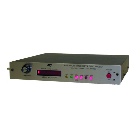
MFJ-1278B MULTI-MODE
Table of Contents
INTRODUCTION......................................................................................................... 1
COMPUTER INTERFACING...................................................................................... 4
MFJ Starter Packs .................................................................................................. 4
Computer Interface with MFJ Starter Pack ............................................................ 5
Computer Interface without MFJ Starter Pack ....................................................... 5
SERIAL PORT SIGNALS ............................................................................................ 5
COMPUTER WITH SPECIFIC SERIAL INTERFACES............................................ 6
Apple Macintosh .................................................................................................... 6
Commodore C64, C128 and VIC-20...................................................................... 7
IBM PCjr................................................................................................................ 7
Radio Shack Color Computer ................................................................................ 8
Color Computers .................................................................................................... 8
IBM PC/XT/AT/386/486 and compatibles Computer ........................................... 8
Other Computers with Nonstandard Serial Ports.................................................... 9
TERMINAL SOFTWARE REQUIREMENTS ............................................................ 10
Apple Macintosh .................................................................................................... 10
Apple II, II+, IIe, IIc .............................................................................................. 10
Commodore C64, C128 and VIC-20...................................................................... 11
IBM PCjr................................................................................................................ 11
IBM and Compatible Computers ........................................................................... 11
Radio Shack Color Computer ................................................................................ 12
Radio Shack Model 100/102 and NEC 8201 ......................................................... 12
MFJ-1278B SERIAL PORT PIN FUNCTIONS........................................................... 12
COMPUTER BAUD RATE ......................................................................................... 13
Autobaud................................................................................................................ 13
Changing Terminal Baud Rate ............................................................................... 14
VERIFYING SERIAL PORT OPERATION................................................................ 15
PARALLEL PRINTER PORT...................................................................................... 16
Printer Port Connection.......................................................................................... 16
Printer Consideration ............................................................................................. 17
Printer Port Test ..................................................................................................... 17
RADIO INTERFACING............................................................................................... 18
MFJ-1278B Radio Ports ........................................................................................ 18
RADIO PORTS CONNECTION.................................................................................. 19
HANDHELD RADIO CONNECTION ........................................................................ 20
RADIO INTERFACING METHODS .......................................................................... 21
Method 1: Direct Connection to Microphone and Speaker.................................... 21
Transmit Audio Level Adjustment for Method I Interface ............................... 21
Setting the Receiver Audio Input Level............................................................ 22
TABLE OF CONTENTS
Advertisement
Table of Contents
Troubleshooting

Related Manuals for MFJ Multi-mode Data Controller MFJ-1278B


Summary of Contents for MFJ Multi-mode Data Controller MFJ-1278B
-
Page 1: Table Of Contents
MFJ-1278B MULTI-MODE Table of Contents INTRODUCTION... 1 COMPUTER INTERFACING... 4 MFJ Starter Packs ... 4 Computer Interface with MFJ Starter Pack ... 5 Computer Interface without MFJ Starter Pack ... 5 SERIAL PORT SIGNALS ... 5 COMPUTER WITH SPECIFIC SERIAL INTERFACES... 6 Apple Macintosh ... - Page 2 MFJ-1278B MULTI-MODE FSK CONNECTION... 29 GETTING STARTED ... 30 First Steps... 30 Basic Commands ... 30 SERIAL PORT CONFIGURATION ... 31 Parity and Word Length ... 32 Echos... 32 New Lines and Line Wrapping... 33 THE MFJ-1278B MULTI-MODE MODEM... 33 OPERATIONAL MODES ...
- Page 3 MFJ-1278B MULTI-MODE CONNECT... 56 SPEEDup/SPEEDdown ... 56 AUTOMATIC ON-LINE COMPRESSION... 56 FLOW CONTROL... 56 AMTOR while in PACTOR mode ... 56 Amtor Detection in Pactor... 57 PACTOR STATUS INDICATORS..57 PACTOR MAILBOX ... 58 Setting Up your Pactor Mailbox... 58 General Overview ...
- Page 4 MFJ-1278B MULTI-MODE Summary of AMTOR Contact Sequence ... 90 NAVTEX OPERATION... 91 Navtex Stations and Frequencies ... 91 Navtex Operation ... 91 FAX OPERATION ... 94 FAX Formats... 95 FAX Frequency... 96 FAX Installation... 96 Printer Connection ... 96 Receiving FAX... 97 Receiving FAX to the Printer ...
- Page 5 MFJ-1278B MULTI-MODE Packet Timing... 125 Radio Baud Rate... 126 Special Protocol Timing ... 127 Monitor Functions... 127 Real-Time Clock and Time Stamping ... 128 Multi-Connect Guide... 129 Setting the MFJ-1278B to Normal Operation... 129 How do I Invoke Multi-Connect? ... 129 Easy-Mail Mailbox...
- Page 6 MFJ-1278B MULTI-MODE Link Status Messages ... 302 MFJ-1278B SPECIFICATIONS... 305 GENERAL DESCRIPTION ... 306 DETAILED CIRCUIT DESCRIPTION ... 307 Oscillator... 307 Dividers and Baud-rate Generator... 307 CPU Complex ... 308 Serial Interface ... 308 Watch-dog Timer ... 309 Modem ... 309 Power Supply ...
- Page 7 MFJ-1278B MULTI-MODE Comprehensive Alignment Procedure... 340 Set Modulator Tones Using Built-in Calibration Software... 340 Demodulator Center Frequency Alignment ... 341 Tuning Indicator Alignment ... 342 CW MODEM TUNE-UP PROCEDURE ... 346 Detailed CW Demodulator Alignment Procedure... 347 AUDIO OUTPUT CALIBRATION ... 350 Audio Output Level Adjustment Procedure ...
- Page 8 MFJ-1278B MULTI-MODE TABLE OF CONTENTS...
-
Page 9: Introduction
MFJ-1278B MULTI-MODE INTRODUCTION INTRODUCTION Welcome to the exciting world of Amateur Digital Communications. By choosing the MFJ- 1278B, you have chosen the most versatile and powerful Multi-mode Data Controller manufactured for the Amateur Radio Service. The MFJ-1278B interfaces your radio with any personal computer that has an RS-232 or TTL level Serial Port and a terminal program. - Page 10 MFJ-1278B MULTI-MODE INTRODUCTION The new "packet collision prevention" features -- Prioritized Acknowledgments and Slottime are installed. This new technology helps prevent many packet collisions inherent in the current packet protocol. The EPROM containing the MFJ-1278B firmware, previously 512K bits, has been expanded to 1 Megabits giving the MFJ-1278B twice the room to grow in.
- Page 11 Starter pack for Commodore C64/128 MFJ-1287B Starter pack for Macintosh MFJ-1290 Starter pack for Amiga MFJ-1272B MFJ-1278B to Microphone switch box MFJ-5024 Radio connecting cable for Icom/Yaesu/RS HTs MFJ-5026 Radio connecting cable for Kenwood HTs MFJ-5080 Radio connecting cable for Yaesu 8-pin radio...
-
Page 12: Computer Interfacing
MFJ-1278B MULTI-MODE COMPUTER INTERFACING You are now ready to connect your MFJ-1278B to your station's computer or terminal. Throughout this manual we will use the term "computer" to refer to the computer or terminal you use to communicate with your MFJ-1278B. The MFJ-1278B communicates with your computer through a serial port, using signals corresponding to a standard called RS-232C. -
Page 13: Computer Interface With Mfj Starter Pack
MFJ-1278B MULTI-MODE Computer Interface with MFJ Starter Pack If you are using one of the MFJ Starter Packs, you should use the cable provided to connect the MFJ-1278B to your computer. Follow the instruction manual provided with the Starter Pack to operate the terminal program and to connect the MFJ-1278B to your computer. When finished with installation of the MFJ-1278B proceed to the "Computer Baud Rate", for further information about TNC installation. -
Page 14: Computer With Specific Serial Interfaces
MFJ-1278B MULTI-MODE Many computers require a serial port adapter card. These cards incorporate the circuitry necessary to add an RS-232C port to the computer. Some popular models in this category are the Apple II series, the IBM Personal Computer, many Radio Shack computers, and the Sanyo MBC-55X series. -
Page 15: Commodore C64, C128 And Vic-20
MFJ-1278B MULTI-MODE Commodore C64, C128 and VIC-20 The MFJ-1278B has a built-in TTL-level port for interfacing with the Commodore C64, C128 or the VIC-20 computers. You do not need a RS-232C converter to interface with the MFJ-1278B. An optional Starter Pack for the C-64, C-128 or the VIC-20 is available from MFJ Enterprises, Inc. -
Page 16: Radio Shack Color Computer
MFJ-1278B MULTI-MODE Radio Shack Color Computer The Color Computer series (except for the Micro Color Computer) uses a 4-pin DIN-style connector for its serial port. If you wish to construct your own cable, the information in Figure 2-2 will be helpful. All necessary parts should be available from Radio Shack dealers. Color Computer Fig. -
Page 17: Other Computers With Nonstandard Serial Ports
MFJ-1278B MULTI-MODE If your computer is configured as DCE, you will have to wire pin 2 of your MFJ-1278B to pin 3 of the computer RS-232C connector. Then wire pin 2 of the computer's RS-232C connector to pin 3 of your MFJ-1278B. Please note that pin 7 of the computer's RS-232C connector will still connect to pin 7 of your MFJ-1278B serial port. -
Page 18: Terminal Software Requirements
MFJ-1278B MULTI-MODE TERMINAL SOFTWARE REQUIREMENTS Any software package that enables your computer to act as an ASCII terminal with an ordinary telephone modem should work with your MFJ-1278B. If you have a program that you have used successfully with a telephone modem and that you are familiar with, use that program to communicate with your MFJ-1278B. -
Page 19: Commodore C64, C128 And Vic-20
MFJ-1278B MULTI-MODE COMPUTER INTERFACING Commodore C64, C128 and VIC-20 The optional Starter Pack for the C-64, C-128 and VIC-20 is available from MFJ Enterprises, Inc. or from any dealer of MFJ products. Included in the Starter Pack is a cable to connect the MFJ-1278B TTL port to the user I/O port on the Commodore computer. -
Page 20: Radio Shack Color Computer
MFJ-1278B MULTI-MODE Radio Shack Color Computer There are several terminal programs available for the Color Computer. You will probably want to use a commercial program (rather than writing your own) since the Color Computer has a "software UART" that is difficult to program in BASIC. Some of the terminal programs available are COLORCOM 64, AUTOTERM and RICKEYTERM (for Coco III). -
Page 21: Computer Baud Rate
MFJ-1278B MULTI-MODE Pin 3 Receive Data The Receive Data pin is an output line from the MFJ-1278B on which the attached device receives data. The attached device is generally a computer or data terminal. Pin 4 Request To Send The Request To Send pin is an input line to the MFJ-1278B on which the attached device requests clearance to transmit data to the MFJ-1278B. -
Page 22: Changing Terminal Baud Rate
MFJ-1278B MULTI-MODE COMPUTER INTERFACING time the MFJ-1278B signs on you will not need to press the return key to execute the Autobaud routine. In setting AUTOBAUD to OFF, you should remember that if you change the terminal program baud rate is changed, then MFJ-1278B will no longer be able to match the new baud rate. -
Page 23: Verifying Serial Port Operation
MFJ-1278B MULTI-MODE VERIFYING SERIAL PORT OPERATION Now that you have a terminal program and the connecting cable for attaching the MFJ-1278B to your computer, you are ready to verify that the MFJ-1278B will communicate with your computer. Turn on your computer. Load and run the terminal program. Set the parameter of the terminal program as follow: Word Length 8 bits... -
Page 24: Parallel Printer Port
Packet, SSTV or FAX pictures. If you want to print graphics, then you should connect the printer to the MFJ-1278B printer port. In this case the printer must be either EPSON or IBM graphic compatible in order to insure successful graphic receiving to the printer. -
Page 25: Printer Consideration
Printer Consideration The MFJ-1278B printer port will work with any printer that is compatible with EPSON or IBM graphics. Printers that are not EPSON or IBM graphics compatible can not be used to print FAX or SSTV pictures. In addition to being able to print such as weather FAX, FAX and SSTV pictures, the printer connected to the MFJ-1278B printer port can also print incoming text in all modes as it is received on the screen. -
Page 26: Radio Interfacing
MFJ-1278B MULTI-MODE RADIO INTERFACING Computer interfacing, covered in the previous chapter, is only half the interfacing task. The other half is connecting your MFJ-1278B to your radios. MFJ-1278B Radio Ports Interfacing the MFJ-1278B to your radios involves connecting the following signals at Radio Port 1 and Radio Port 2. -
Page 27: Radio Ports Connection
MFJ-1278B MULTI-MODE RADIO INTERFACING RADIO PORTS CONNECTION The MFJ-1278B gives the user two (2) radio ports. This allows for both FM and HF operation from either radio port. Since the radio ports are independent of each other, the user is not restricted to FM or HF operations. The radio ports on the MFJ-1278B allow an FM radio and an HF radio to be connected at all times. -
Page 28: Handheld Radio Connection
MFJ-1278B MULTI-MODE RADIO INTERFACING HANDHELD RADIO CONNECTION Some HTs key the transmitter by drawing a small amount of current from the microphone input pin (see Fig. 3-3 below). Radios with this type of special keying circuit are ICOM-2AT (tm) and Yaesu FT-x09, FT-x3, FT-727 (tm) and others. Appendix A at the end of this instruction manual provided pin designation for some of the radios. -
Page 29: Radio Interfacing Methods
MFJ-1278B MULTI-MODE RADIO INTERFACING METHODS The MFJ-1278B allows radio connection without any modifications to the radio or any signal balancing devices in the cables. There are two types interfacing methods presented in this chapter. Method 1: Direct Connection to Microphone and Speaker For Method 1, shown in Fig. -
Page 30: Setting The Receiver Audio Input Level
MFJ-1278B MULTI-MODE With the MFJ-1278B keying the transmitter and transmitting the higher of the two tones, adjust the transmit audio level as follows. With a small flat-tipped screwdriver, adjust trimpot located on the left side of them MFJ-1278B (R157 for radio 1 or R158 for radio 2) while you listen to the monitoring receiver. -
Page 31: Method 2: Accessory Jack Or Interface Box Connection
MFJ-1278B MULTI-MODE RADIO INTERFACING The bandwidth of the receiver audio will have an effect on modem sensitivity to false DCD. Some receivers produce wideband audio that will NOT produce any false DCD activity regardless of the threshold control setting. In this case, set the DCD threshold control to its maximum clockwise rotation. - Page 32 MFJ-1278B MULTI-MODE Fig. 3-7 External Interface Box If you built the external interface box as in Fig.3-7, then follow this procedure to adjust R(s). Install JMP J on the MFJ-1278B PC board. Temporarily solder a variable resistor in place of R(s) Fig. 3-7. The maximum value of this resistor can be determined by experiment.
- Page 33 MFJ-1278B MULTI-MODE Transmit Audio Level Adjustment for Interface Method II Turn on the MFJ-1278B and computer and start your terminal program. Enter the modem calibration procedure by typing CALIBRA Press the K key to key the transmitter, then tap the space bar until the higher of the two tones is heard.
- Page 34 MFJ-1278B MULTI-MODE RADIO INTERFACING Receiver Audio Setting The modem in your MFJ-1278B is equipped with an advanced phase coherence type data carrier detection (DCD). A threshold control and a sensitive tuning indicator is also provided. Together these can be used to set the correct receive audio level for the modem. These can also be used to optimize the DCD characteristics for the various methods of operation.
-
Page 35: Monitor Speaker Connection
MFJ-1278B. The MFJ-1278B requires only one speaker for RADIO 1 and RADIO 2. The MFJ-1278B will automatically switch the monitor speaker to the radio port in use. If wiring of a speaker plug is necessary, use a 3.5 mm (1/8") mono or stereo plug for this connection. - Page 36 MFJ-1278B MULTI-MODE RADIO INTERFACING CW INSTALLATION The MFJ-1278B user can send and receive CW by using your computer keyboard. However, the MFJ-1278B expands CW operating fun by allowing you to connect an iambic paddle to the KEY input jack of the MFJ-1278B. This feature allows you to use the MFJ-1278B as a CW memory keyer.
-
Page 37: Fsk Connection
MFJ-1278B MULTI-MODE RADIO INTERFACING FSK CONNECTION If your HF radio permits FSK operation, an FSK output is provided. The FSK output is at pin 8 of the TTL port on the rear panel of the MFJ-1278B. Only two lines (Pin-8 FSK and Pin- 3 ground) are needed in making the FSK connection to your radio. -
Page 38: Getting Started
MFJ-1278B MULTI-MODE GETTING STARTED This chapter will guide you through the basic operation on all the modes that the MFJ-1278B is capable of performing. It contains the basic information required to operate PACKET, PACTOR, RTTY, ASCII, CW, AMTOR, NAVTEX, FAX, SSTV and CW Memory Keyer. Note: In this section you will see this symbolism, <ENTER>. -
Page 39: Serial Port Configuration
MFJ-1278B MULTI-MODE followed by a carriage return. Now let's try entering your callsign using one of the basic commands, MYCALL, by typing from the cmd command prompt: MYCALL K5FLU followed by a carriage return. The MFJ-1278B will respond with: MYCALL was NOCALL cmd: followed by the the system command mode prompt, cmd:. -
Page 40: Parity And Word Length
MFJ-1278B MULTI-MODE Parity and Word Length If you are using one of the optional MFJ Starter Packs, then you should follow the instructions given by the terminal program documentation with the starter pack. If you are not using one of the MFJ starter packs, then you should use the following instructions to set the parity and word length for the MFJ-1278B. -
Page 41: Basic Operation
MFJ-1278B MULTI-MODE BASIC OPERATION New Lines and Line Wrapping If everything displayed appears to be double-spaced, your computer is adding an extra linefeed (<LF>) whenever it displays a carriage return (<ENTER>). Set AUTOLF OFF to keep the MFJ-1278B from also adding an <LF>. If you change equipment you may have to set AUTOLF ON to restore the MFJ-1278B's automatic linefeeds. -
Page 42: The Mfj-1278B Multi-Mode Modem
MFJ-1278B MULTI-MODE THE MFJ-1278B MULTI-MODE MODEM The MFJ-1278B modem has five sets of pre-set modem components. components allow the MFJ-1278B to operate efficiently in its various modes of operation. These modes of operation include VHF and HF Packet, PACTOR, AMTOR, VHF RTTY, HF RTTY, VHF ASCII, HF ASCII, CW, Modulated CW, CW Memory Keyer, 16 gray level FAX (including Weather FAX), color SSTV and monitoring of NAVTEX. -
Page 43: Operational Modes
MFJ-1278B MULTI-MODE OPERATIONAL MODES Verifying Operation Status Upon initial power up, the MFJ-1278B defaults to VHF Packet mode. The radio baud rate defaults to 1200 baud. Radio port 1 is the default radio connection. You can verify the operating status of the MFJ-1278B at any time by using the command MODE after the display of the CMD: prompt. -
Page 44: Operation
MFJ-1278B MULTI-MODE On the CW, MCW and Memory Keyer operation modes, instead of selecting a baud rate you will select CW sending speed by entering a number from 5 thru 99. If you do not select a speed, the MFJ-1278B will use the last speed selected. The default value is 20 WPM. MODE OPERATION DEFAULT... -
Page 45: Loading The Memory Buffers
MFJ-1278B MULTI-MODE Loading the Memory Buffers The ten memory buffers are empty when the MFJ-1278B is first initialized. To load the memory buffers the user can invoke the BUF command. To load the memory buffers, please note the example below for loading buffer 1. The MFJ- 1278B must be in COMMAND mode: BUF1 The QTH here is Starkville, Mississippi. -
Page 46: Memory Repeat And Buffer Repeat Time
MFJ-1278B MULTI-MODE Memory Repeat and Buffer Repeat Time Of the ten memory buffers provided by the MFJ-1278B, memory buffer 0 has a repeat function. The user can enable the repeat function, moreover specify a time interval. The BUFTIME specifies the time interval between repeats of memory buffer 0. Values from 0 to 65,535 are suitable for the BUFTIME command. -
Page 47: Tuning Indicator
MFJ-1278B MULTI-MODE Note : If BUFTIME is a non-zero value, MFJ-1278B will automatically release the PTT line and revert to the receive mode between repeats. This allows you to monitor the frequency for any replies to your message. If the MFJ-1278B is not interrupted during the pre-set delay time, it will continually repeat until buffer 0 is interrupted. -
Page 48: Packet Operation
MFJ-1278B MULTI-MODE PACKET OPERATION VHF Packet If you are not familiar with packet operation, then you can learn quite a bit about it with the MFJ-1278B without transmitting anything. For your first experiments, the MFJ-1278B will be "talking to itself," allowing you to become familiar with it before you go on the air. If you are already familiar with the packet operation, then you may not want to perform this exercise. - Page 49 MFJ-1278B MULTI-MODE The <ENTER> causes your message to be put into a packet, or "packetized," and transmitted. (We explain in the next chapter how you can use a different character to send packets.) The underlined text is a message that the MFJ-1278B received in a packet and displayed. Whenever you are in Converse Mode anything you type will be assembled into a packet addressed to the station you are talking to and transmitted.
-
Page 50: Digipeating
MFJ-1278B MULTI-MODE Be sure to remove the jumper from JMP10 after you complete this "Connecting and Disconnecting Exercise". Digipeating You may wish to have a QSO with another packet station that is beyond your direct radio range. If a third packet station is on the air and both you and the station you want to talk to are in range of this third station, that station can relay your packets. -
Page 51: Unsuccessful Connections
MFJ-1278B MULTI-MODE Unsuccessful Connections Sometimes you will initiate a connect sequence that can't be completed. The station may not be on the air, or it may not be within range of your station. You may have even mis- typed the other call sign. If the MFJ-1278B does not get a response to its first connect packet, it will try again. - Page 52 MFJ-1278B MULTI-MODE Since you are not connected to another station your packets are sent to the address "CQ," i.e., anyone. The packet you sent was "heard" by the MFJ-1278B and displayed, along with the sending station and the destination. If you also want to see any intermediate digipeater stations being used, you can set MRPT ON.
-
Page 53: Your First Packet Qso
MFJ-1278B MULTI-MODE Your First Packet QSO Although there are still a number of features you should be familiar with, you are probably eager to get on-the-air and try out your new MFJ-1278B. Arrange to have another packet operator get on the air to help you get started. Make sure that your friend will be close enough to ensure solid copy, with no FM "popcorn"... -
Page 54: Digipeating
MFJ-1278B MULTI-MODE Exchange several messages to get a feel for this new mode. If you monitor the radio transmit indicators and listen to the speaker audio from the two rigs, you will have a better idea of what is happening. Your radio will be inactive most of the time, even while you are actually typing. -
Page 55: Monitoring On The Air
MFJ-1278B MULTI-MODE Monitoring on the Air This is a good time to try out the MFJ-1278B's monitor functions. While you and your friend are separately connected, type <CTRL-C> cmd: MONITOR ON cmd: MCON ON cmd: CONVERS You will be able to see both your "conversation" and your friend's conversation. Also try HEADERLN ON and MHEARD. - Page 56 MFJ-1278B MULTI-MODE If you make several mistakes in a line, or if you change your mind, you may want to cancel the whole line rather than rubbing out the characters one at a time. You can cancel the line by typing <CTRL-X>. The MFJ-1278B will display a <BACKSLASH> followed by a <ENTER>.
-
Page 57: Basic Hf Packet Operation
MFJ-1278B MULTI-MODE BASIC OPERATION BASIC HF PACKET OPERATION The requirements for optimum performance with a typical HF or OSCAR 10 path are very different compared to local VHF FM environment. Lower signal to noise ratios require lower baud rates, noise spikes and fades require shorter packet lengths, and a higher rate of false carrier detects lowers the total usable dynamic range in the audio input. -
Page 58: Hf Packet Operation Hints
MFJ-1278B MULTI-MODE If you cannot contact anyone using another frequency, call CQ on one of the above mentioned frequencies. If you do make a contact with someone, then QSY immediately after establishing contact! Be careful on 20 meters especially that you don't operate +/- 2KHz around 14.100 MHz (you will cause interference to propagation beacons and give packet a bad name...). -
Page 59: Pactor
Verify the power switches to both the computer and the MFJ-1278B are OFF. Connect the MFJ-1278B to both the radio and the computer. Connect the radio to a dummy load. Set the POWER switch on the computer to the ON position, then load the terminal program. BASIC OPERATION... -
Page 60: Fec Unproto Operation
MFJ-1278B MULTI-MODE Now that we have the MFJ-1278B signed-on to the computer, let's put it into the PACTOR mode. To put the MFJ-1278B into PACTOR mode, please type the following: MODE PT <ENTER> The MFJ-1278B will respond with: [MFJ PACTOR $2c-1022 free] p_cmd: At the above prompt, you are in the PACTOR mode. -
Page 61: Pactor Arq
MFJ-1278B MULTI-MODE PACTOR ARQ For ARQ operation you will need to know the other person's callsign. Normally you can get the other person's call by monitoring the channel for connect requests or other ARQ contacts. To establish contact with another station, you must be at the p_cmd: prompt. To initiate a connect sequence, please type the following: C n <ENTER>... -
Page 62: Monitoring Amtor Arq Requests
AMTOR ARQ requests monitored while the MFJ-1278B in PACTOR mode. If the controller detects your selcall in an AMTOR ARQ request packet, the controller will switch to AMTOR and try to establish the link. This feature allows someone who doesn't have PACTOR capability to connect to you in AMTOR mode. - Page 63 "NEWMODE ON" procedures in packet. The MFJ- 1278B is in COMMAND mode, if the p_cmd: prompt is on the computer screen. To switch to CONVERSE mode from COMMAND mode the K key followed by an <ENTER> is issued by the user.
-
Page 64: Connect
MFJ-1278B MULTI-MODE BASIC OPERATION To prevent Uncontrolled Disconnects, we are unable to listen to all kinds of third party Pactor transmissions for (WAIT x Cycle_Time) seconds after receiving the other side's last disconnect. This includes all unproto and connected packets, along with connect requests. The actual cycle time is 1.25 or 1.4 seconds. -
Page 65: Amtor Detection In Pactor
MFJ-1278B MULTI-MODE AMTOR selective callsign in the "a_cmd:" MYSELCAL parameter. Furthermore, you must have the appropriate sideband, usually, LSB selected because unlike PACTOR, AMTOR is polarity dependent. Amtor Detection in Pactor The MFJ-1278B's Pactor continuously monitors the channel for Pactor packets, and for AMTOR call packets that match your AMTOR SELCALL. -
Page 66: Pactor Mailbox
MFJ-1278B MULTI-MODE PACTOR MAILBOX The MFJ-1278B now includes a new feature called a PACTOR MAILBOX. In this section we will cover basic operation of the new Pactor Mailbox, and the operative commands. The Pactor Mailbox includes the basic commands of the Packet mailbox. The Pactor Mailbox is very simple and easy to use. - Page 67 MFJ-1278B MULTI-MODE From the cmd: prompt please type the following: MODE PT <ENTER> the MFJ-1278B will respond with: [MFJ PACTOR $2c-1022 free] followed by the p_cmd: prompt on the next line. The $2c is the checksum of MFJ's Pactor release. You will probably notice a slight delay in obtaining the p_cmd: prompt. This is because the MFJ-1278B is figuring up the Pactor checksum, this is perfectly normal.
-
Page 68: General Overview
From this prompt you as the SYSop can Kill, List, Read, Send messages in the mailbox. You can also send private messages, edit the messages headers, bank switch the mailbox RAM. General Overview This section will deal with the Pactor Mailbox in general. - Page 69 MFJ-1278B MULTI-MODE Kill Allows the remote user to kill messages that are addressed specifically to the user. If the message is not addressed to the user, then the mailbox will respond with "not yours", and present the user with the mailbox prompt. Kill ## Allows the remote user kill a message in a particular slot, nn.
- Page 70 MFJ-1278B MULTI-MODE If the above conditions are met then all the remote user must type: K <ENTER>, followed by a changeover characters, CTRL-Y. This will go out to Mailbox, then the messages with the message flags set to Y with all of the proper callsigns will be killed.
-
Page 71: Detailed Pactor Mailbox Overview
MFJ-1278B MULTI-MODE Read This command lets you read messages addressed to you. When you list the messages in the mailbox you notice an N flag next to the messages which you have not read. Once you read those messages the N flag will change to a Y flag. This is an indicator to both you and the SYSOP that the messages have been read. - Page 72 MFJ-1278B MULTI-MODE First a remote must establish a connection to your Mailbox, via your Pactor callsign. If your Pactor Mailbox is ON, then it will answer back with the Pactor Mailbox prompt: Mailbox Ready n free de callsign (H(elp), K, L, R, S)> The n free is the amount of RAM space available for messages.
- Page 73 MFJ-1278B MULTI-MODE There are two (2) different ways the remote user can kill messages. The first is give in the example below: a. To kill a message in a particular slot, the remote user would type: K## <ENTER> Where the ## is the message number the remote user wants to kill. The Pactor Mailbox will respond with: Message ## deleted;...
- Page 74 MFJ-1278B MULTI-MODE The Mailbox will respond with a list of currently used slots in the following format: Slot:## t m To: From: Where Slot## column is the number of the slot that the messages are in. The number of message slots present in the standard 32K Mailbox is 99. The lower case t is the Type Flag block.
-
Page 75: Mailbox Messages
MFJ-1278B MULTI-MODE is proper Pactor etiquette. If you access your Mailbox via the SYsop command, then you must issue a CTRL-C to exit the Mailbox and return to command mode. The SYSOP mode is accessed through the Packet mailbox, as mentioned earlier in this section. -
Page 76: Cw Operation
MFJ-1278B MULTI-MODE CW OPERATION The MFJ-1278B provides many unique features in the CW mode that are not found in other multi-mode controllers. The MFJ-1278B can key your CW transceiver in the CW mode of operation. The MFJ- 1278B can accommodate either positive (direct) or negative (grid block) keying voltages. The MFJ-1278B also has a code practice mode built-in, that can be used with VHF FM radios in the Modulated CW (MCW) mode. -
Page 77: Receiving Cw
MFJ-1278B MULTI-MODE Receiving CW The MFJ-1278B receives international Morse Code from 1 to 99 WPM. Reception of alphabetic and numeric characters, including the puncuations and prosigns listed in Table 4- From command mode, put the MFJ-1278B in the CW Mode by typing: MODE CW,xx <ENTER>, where "xx"... -
Page 78: Transmitting Cw
MFJ-1278B MULTI-MODE If the AUTOTRAC command is OFF, then before the MFJ-1278B can copy the tuned-in CW signal, it must be manually locked to the speed of the received signal. To manually lock the MFJ-1278B to the incoming signal, type a CTRL-U. The MFJ-1278B will respond with "locking...". -
Page 79: Transmitting From Memory Buffers
MFJ-1278B MULTI-MODE If CWSEndch is left at the default setting of 255 or $FF, the MFJ-1278B will transmit all characters immediately when typed. The requirement for pressing the <ENTER> is eliminated. Note : If you are using a terminal program such as "PROCOMM" for IBM PC and compatibles that buffers the transmit data, then a CARRIAGE-RETURN will be needed to transmit. -
Page 80: Tuning Your Radio
MFJ-1278B MULTI-MODE Tuning your Radio The MFJ-1278B lets you tune your radio with the TUNE command. The TUNE command is issued from the command mode. The user can use the TUNE command in any of the MFJ- 1278B operating modes. The TUNE command activates the PTT line for 30 seconds. -
Page 81: Setting Up The For Code Practice
MFJ-1278B MULTI-MODE Setting Up the for Code Practice You can monitor the random code sent by the MFJ-1278B without a radio connected. In order to monitor the random code, attach a small speaker to the "SPEAKER" jack, located on the back panel of the MFJ-1278B Note : If a radio is connected and you do not wish to transmit the random code, the radio should be turned OFF. -
Page 82: Cw Contest Memory Keyer Operation
MFJ-1278B MULTI-MODE BASIC OPERATION CW CONTEST MEMORY KEYER OPERATION For CW enthusiasts who like to use a key paddle to send CW, the MFJ-1278B provides an input for an iambic key paddle. See CW KEY PADDLE INSTALLATION in chapter 3 in this MFJ-1278B manual for installation of your iambic key paddle. -
Page 83: Modulated Cw Operation
MFJ-1278B MULTI-MODE MODULATED CW OPERATION The MFJ-1278B allows the transmission of CW code practice over a VHF FM radio. To send code practice over a VHF FM radio, the user would use the Modulated CW mode, or MCW. When using the Modulated CW, the MFJ-1278B will key the PTT line of the Radio port and send a keyed audio tone to the microphone input of your radio. -
Page 84: Baudot Rtty & Ascii Operation
MFJ-1278B MULTI-MODE BAUDOT RTTY & ASCII OPERATION The user can configure the MFJ-1278B RTTY/ASCII modems to copy several shifts, including 170, 425, and 850 Hz shifts. The user can use the MODE command to configure the RTTY/ASCII modems for the different shifts. The MFJ-1278B will transmit and receive RTTY and ASCII at speeds of 45, 50, 57, 75, 100, 110, 150, 200, and 300 baud. -
Page 85: Rtty And Ascii Receiving
MFJ-1278B MULTI-MODE If you do not specify a baud rate for the RTTY or ASCII modes, the MFJ-1278B selects the default baud rates. The default baud rates for the RTTY and ASCII modes are 45 and 110 baud respectively. You can select a desired speed by typing the baud rate after the two character code. -
Page 86: Baudot Rtty Operation Hints
MFJ-1278B MULTI-MODE Note: If the MFJ-1278B is not in transmit mode (i.e. in receive mode), then in order to initiate transmission from a buffer, you must type CONTROL-T twice then enter a number for the buffer. You can tell if the MFJ-1278B is in transmit mode, by observing the PTT LED on the front panel. -
Page 87: Commercial Rtty Reception
MFJ-1278B MULTI-MODE To enter the converse mode type: This will take the MFJ-1278B out of the command mode and into converse mode. When the MFJ-1278B enters converse mode, the STA will illuminate. Also after entry into converse mode the MFJ-1278B is in receive mode. You can enter transmit mode by typing CONTROL-T. -
Page 88: Automatic Signal Analysis
Last it will display the setting of what it will change the RXInvert command to (On or Off). This is what ASA will switch the MFJ-1278B to, if the user accepts its result. - Page 89 The MFJ-1278B will switch to the 300 baud HF packet mode. If the user just issues the OK command, then the MFJ-1278B will switch to the 300 RTTY or ASCII mode. The number of data bits ASA analyzed, determines if the MFJ-1278B switches into RTTY or ASCII modes.
-
Page 90: Mars Operation
MFJ-1278B MULTI-MODE MFJ-1278B will enter converse mode and begin to display text normally. If another RTTY or ASCII signal from another station is received, RBIT must be reset to copy that signal by following the same procedure as described above. RBIT can be set to normal (no inversion) by setting it to "RBIT 0". -
Page 91: Operating Mars With Multicom For Ibm
MFJ-1278B MULTI-MODE BASIC OPERATION Once you have set your operating mode, the user must press the K key and a <ENTER> in order to enter RECEIVE mode. The MARS operator is now ready to receive MARS traffic. The operator must then tune the VFO on the radio so the tuning indicator on the MFJ-1278 is centered on the bar graph display. -
Page 92: Marsmode 1- Qso Mode
MFJ-1278B MULTI-MODE MARSMODE 1- QSO Mode In the MARS QSO mode the Transmit translations are as follows: All carriage returns are converted to CR/CR/LF, or to LF only if preceding character was also CR. "NNNN" is sent as "NNNN" followed by 12 LTRS Characters are translated as follows: Key Press Trans. -
Page 93: Amtor Operation
MFJ-1278B MULTI-MODE BASIC OPERATION AMTOR OPERATION AMTOR, AMateur Teletype Over Radio), an error correcting protocol suite, is fully supported by the MFJ-1278B. Two modes are available with AMTOR. These are mode A and mode B. From command mode, AMTOR modeB is entered by typing: MODE AM <ENTER>... -
Page 94: Operating Mode A
MFJ-1278B MULTI-MODE Examples are: Amateur callsign is N2WX; Amtor MYSELCAL is NNWX Amateur callsign is WB2SPE; Amtor MYSELCAL is WSPE AMTOR depends on everyone having a unique selective call. If you find there is already a station using the same call that you would use then you may need to base your ID upon the call district that you're in. -
Page 95: Monitoring Mode A, "Arq
MFJ-1278B MULTI-MODE BASIC OPERATION Monitoring Mode A, "ARQ" The LISTEN command is useful for monitoring other people's ARQ contacts. To use, tune in a Mode A signal and type LISTEN. Both the CON and STA leds will light until the station is synchronized, at which time the MFJ-1278B will start to receive. - Page 96 MFJ-1278B MULTI-MODE AMTOR Status LED Indicators The CON and STA LEDs have special meanings in the AMTOR modes. STA OFF CON OFF This led combination indicates that Mode B is unlocked, and in STANDBY mode. Standby mode is where the MFJ-1278B is ready to respond to Mode A or B "FEC" Amtor signals. The MFJ-1278B will also print Mode S "SELCAL"...
- Page 97 MFJ-1278B MULTI-MODE in idle mode. If you can hear both sides, you can hear the alternate chirps as they are in sync with each other. If you operate Mode B or Mode S, then you should have no problems with AMTOR. These are the broadcast modes and are almost identical to teletype in the way you make contacts.
-
Page 98: Summary Of Amtor Contact Sequence
LISTEN or LI allows you to monitor mode A (ARQ), and switches from mode B. Issuing an R will switch from mode A to mode B from the a_cmd: prompt. ARQ xxxx connects you with a station heard calling cq. -
Page 99: Navtex Operation
MFJ-1278B MULTI-MODE NAVTEX OPERATION Navtex is a new direct printing service operating on 518 KHz. NAVTEX stands for Navigational Telex. Navtex broadcasts urgent weather, navigational and other information that is intended for ships. Navtex Stations and Frequencies Navtex Stations currently cover most coastal areas of Europe and the Eastern United States. West Coast Stations for the United States are in various phases of planning or construction, and will begin transmitting within a few years. - Page 100 MFJ-1278B MULTI-MODE letter identifies the type of message. Refer to the following explanation of the NAVMSG command for the different types of messages that are identified by this second letter. The NAVMSG and NAVSTN commands allow you to choose both the types of messages you receive and the stations you receive.
- Page 101 MFJ-1278B MULTI-MODE The types of Navtex messages currently are: A. Navigational warnings B. Storm Warnings C. Reports of Ice D. Search/Rescue Information E. Weather forecasts F. Pilot Service Messages G. DECCA System H. LORAN-C I. Omega Systems J. SATNAV Systems K thru-Z are not in use at this time.
-
Page 102: Fax Operation
FAX operations with the MFJ-1278B, does not require any special computer or software to receive FAX pictures on your Epson graphics compatible printer. However, to print a FAX picture to your computer screen or to save FAX pictures to disk, you need software that allows these operations. -
Page 103: Fax Formats
FAX operation, you should follow the procedure given in its operating instruction manual to receive and transmit FAX. FAX operation procedure given in this instruction only applies to receiving 2-level FAX and printing it to an EPSON graphic printer attached to the MFJ-1278B printer port. BASIC OPERATION Lines per... -
Page 104: Fax Frequency
MFJ-1278B MULTI-MODE FAX Frequency FAX transmitting stations are usually found on the HF bands. Weather FAX stations are generally upper sideband. Some of these stations maintain a regular schedule. Table 4-7 lists the frequencies of some FAX stations. Service Band Frequency (KHz) Weather 3,357.00 4,268.00 4,975.00 6,946.00... -
Page 105: Receiving Fax
Most commands that affect FAX printing default to a value that will allow successful printing. However, before printing, make sure the commands EPSON and PRINTGRA are ON. Printing a FAX image directly to a printer will not function unless EPSON and PRINTGRA are ON. - Page 106 MFJ-1278B MULTI-MODE BASIC OPERATION After selecting the desired FAX mode, type K to leave command mode and enter the CONVERSE mode. Once in CONVERSE mode the MFJ-1278B is in standby-receive mode. This means that the MFJ-1278B is listening to the radio for the distinctive "tic-tic" that indicates the synchronization period at the beginning of a picture.
-
Page 107: Display Fax Picture On Computer Screen & Save It To Disk
MFJ-1278B MULTI-MODE Display FAX Picture on Computer Screen & Save it to Disk The MFJ-1278B firmware does not support printing to your computer screen or allow you to save FAX pictures in disk files. Printing of fax pictures to your computer screen, and saving pictures to disk are a function of the computer software. -
Page 108: Multi-Level Fax Picture Raw Data Format
MFJ-1278B MULTI-MODE The number of graphics characters, "nnn", following a FAX frame header, depends on the FAXMODE. See horizontal density under the FAXMODE command for more information. Multi-level FAX Picture Raw Data Format In FAX mode the MFJ-1278B can provide data thru the RS-232 port in raw data format. With special terminal software which can support this data format, you can display and save multi-gray levels pictures. -
Page 109: Transmitting Fax
MFJ-1278B MULTI-MODE After unbiasing: bit # 7 6 5 4 3 2 1 0 data x x a a a b b b x = don't care a,b = first and second pixel groups Coding: If, prior to unbiasing, the value of the data byte is an ASCII p, q, or r, then the received byte is a sync byte. -
Page 110: Multi-Level Fax Transmitting
MFJ-1278B MULTI-MODE The FAX format is changeable by using the FAXMODE command. supports receive or transmit of all FAX formats listed in Table 4-6 in both transmit and receive. In 2 level FAX, pictures saved under one format may NOT be transmitted under a different format. - Page 111 MFJ-1278B MULTI-MODE BASIC OPERATION The command PIXTONES is used to set the multi-gray levels FAX and SSTV pictures being transmitted. The current PIXTONES is set to 16 gray levels. PIXTONES defines the gray levels of the SSTV and FAX transmitted by the MFJ-1278B. To achieve this you must use a terminal program which supports the multi-gray levels SSTV and FAX transmitting, such the advanced MFJ MultiCom™...
-
Page 112: Creating Fax Pictures For Transmitting
MFJ-1278B MULTI-MODE PIXTONES FAX/SSTV Transmit Values (HEX) Table 4-8: FAX/SSTV Multi-Gray PIXTONES Creating FAX Pictures for Transmitting FAX pictures captured by the MFJ-1278B and saved on disk can be re-transmitted at a later time. However, the FAX pictures must be re-transmitted with the same format with that they were saved. -
Page 113: Slow Scan Television Operation
If you are using a standard terminal program that does not support screen printing of SSTV pictures, you must attach an "EPSON" or "IBM" graphics compatible printer to the MFJ-1278B's parallel printer port in order to allow printing of SSTV pictures. -
Page 114: Sstv Formats
MFJ-1278B MULTI-MODE SSTV Formats The MFJ-1278B provides a dedicated multi-gray level modem for SSTV operation. The modulator and demodulator frequencies of the MFJ-1278B are pre-set at the factory to allow SSTV operation without any recalibration. The MFJ-1278B supports all SSTV formats listed in Table 4-9. -
Page 115: Receiving Sstv Pictures
DIP switches on the printer. "IBM GRAPHICS" mode is not the same as "EPSON GRAPHICS" mode. If you are using an EPSON graphics printer, you should turn the IBM GRAPHICS mode off and set your printer to EPSON GRAPHICS mode. - Page 116 MFJ-1278B MULTI-MODE BASIC OPERATION After entering the SSTV mode and you have properly selected the correct TV format, type: to leave command mode and enter the CONVERSE mode. Once in CONVERSE mode the MFJ-1278B is in standby-receive mode. This means that the MFJ-1278B is listening to the radio for the synchronization signal at the beginning of each SSTV picture.
- Page 117 MFJ-1278B MULTI-MODE TVBreaks are arranged in the following format: White gray Black area area area $ss,$aa,$bb,$cc,$dd,$ee,$ff,$gg,$hh,$ii,$jj,$kk,$ll,$mm,$nn $ss is the Sync value. The default TVBreak value is: $80, $46, $47, $48, $4C, $4F, $52, $54, $59, $5C, $5E, $60, $63, $67, $69 The RXBright command has been updated to support the 16 levels gray.
-
Page 118: Printing Sstv Pictures To The Screen
MFJ-1278B MULTI-MODE Pixtones command serves the same function as the TVBreak command, but in transmitting of SSTV and FAX pictures. Printing SSTV Pictures to the Screen The MFJ-1278B does not support printing graphics to the computer screen without specific terminal software designed for your particular computer. MFJ offers an optional Starter Pack (MFJ-1289) which will allow you to receive SSTV and display to the computer screen. -
Page 119: Saving Sstv Pictures To Disk
MFJ-1278B MULTI-MODE Coding: If, prior to unbiasing, the value of the data byte is an ASCII p, q, or r, then the received byte is a sync byte. Otherwise, the received byte contains actual display information as described above. The color level of each pixel contain in the data byte is given below: white lightest grey darkest grey... -
Page 120: Creating Sstv Pictures For Transmitting
Note that under multi-level SSTV, selection of TVMode for transmitting is not required. After entering the SSTV mode, and selecting the desired TV Mode, enter the CONVERSE mode by typing: Then, switch to transmit mode by typing: CTRL-T Terminal program will sends raw data stream to the MFJ-1278B thru the RS-232 port. - Page 121 MFJ-1278B MULTI-MODE BASIC OPERATION MFJ-1292 "Picture Perfect" Video Digitizer for the IBM and compatible computers allows you to digitized a picture with a Camcorder or video camera. The digitized picture is stored to disk and it can be converted to any of the SSTV formats supported the MFJ-1278B. Converted SSTV picture can be transmitted by the MFJ-1278B.
-
Page 122: Advanced Packet Operation
MFJ-1278B MULTI-MODE ADVANCED OPERATION ADVANCED PACKET OPERATION This chapter describes some other aspects of Packet operation that you will not need to be concerned with for everyday conversational operation. You will want to consult this chapter if you are using your station for special applications such as a Packet Personal Mailbox, Bulletin Board, binary file transfers, Packet picture transfers or running a "host"... -
Page 123: Packet Operating Modes
MFJ-1278B MULTI-MODE So $1B in hexidecimal notation is equal to 27 in standard decimal notation. Table 5-1 presents a list of ASCII character codes that are available in most computer manuals. A table of ASCII codes for control characters follows: Control Mnemonic <CTRL-@>... -
Page 124: Entering Data-Transfer Modes
MFJ-1278B MULTI-MODE stored in the system EPROM. The bbRAM memory stores most of the parameter values in a permanent, but easily changed form. The following commands set special characters that are active in Command Mode. Please refer to the discussions of the special character commands in Chapter 6 for details on the operation of the characters in Command Mode. -
Page 125: Converse Mode
MFJ-1278B MULTI-MODE ADVANCED OPERATION The timing of the automatic entry into data-transfer mode depends on whether you or the other station initiated the connection. If you receive a connect request that your MFJ-1278B accepts, then you will enter data-transfer mode, when your MFJ-1278B sends the connect acknowledgment (ACK) and displays the message: *** CONNECTED TO <callsign>... -
Page 126: Transparent Mode
MFJ-1278B MULTI-MODE The following commands set special characters which are active in Converse Mode. Refer to the discussions of these commands for details on the operation of the characters in Converse Mode. CANLINE Cancel current line CANPAC Cancel current packet COMMAND Command Mode entry DELETE... -
Page 127: Flow Control
MFJ-1278B MULTI-MODE ADVANCED OPERATION The display characteristics of the MFJ-1278B are also modified in Transparent Mode. Data is sent to the computer exactly as it is received over the radio, including all 8 bits of each byte received. Features such as auto-linefeed insertion and screen wrap are disabled, and echoing of input characters is disabled. -
Page 128: Xon/Xoff Flow Control
MFJ-1278B MULTI-MODE ADVANCED OPERATION A computer file transfer program may be unable to process data fast enough to keep up with output from the MFJ-1278B. In order to be sure of reading every character, a computer must respond to interrupts from its I/O devices. Some simple programs may poll the input register for new data. -
Page 129: Hardware Flow Control
MFJ-1278B MULTI-MODE ADVANCED OPERATION Hardware Flow Control Hardware flow control is less likely to depend on the programming of a particular communications program. DTR and CTS are normally used for flow control signals in Transparent Mode. The command XFLOW OFF enables hardware flow control in Converse Mode and Command Mode. -
Page 130: Automatic Operations
MFJ-1278B MULTI-MODE The MFJ-1278B can send an automatic identification packet every 9-1/2 minutes when your station is operating as a digipeater. You can enable this feature with the command HID ON. An ID packet is displayed as follows by a monitoring station: W3IWI-3>ID:W3IWI/R You can request a final identification as you take your station off the air with the command ID. - Page 131 MFJ-1278B MULTI-MODE ADVANCED OPERATION You can have your station periodically send an automatic message by enabling "beacons." A beacon can be used to make general-interest announcements, provide packets for other stations to use to test their ability to receive, or announce the presence of a bulletin-board operation.
- Page 132 If the MFJ-1278B starts sending data before the transmitter is operating or before the receiver has had time to switch from transmitting and lock up on the incoming signal, the packet will not be received properly. The delay between transmitter keyup and the beginning of data transmission is controlled by the command TXDELAY.
-
Page 133: Packet Timing
MFJ-1278B MULTI-MODE 1278B will assume is required for the repeater to drop. If the MFJ-1278B has detected channel activity recently enough that the repeater transmitter should still be on, it will wait only the TXDELAY time before sending data, rather than adding an AXDELAY time as well. -
Page 134: Radio Baud Rate
MFJ-1278B MULTI-MODE ADVANCED OPERATION The wait time is set by the command DWAIT, which specifies 40 ms intervals. If no digipeating is being done by anyone in the local area, this parameter can be set to 0, but in any event it should be set to the same value by all members of a local packet group. In order to avoid unnecessary packet retries, the MFJ-1278B implements a collision- avoidance strategy which applies to all packets except those being digipeated. -
Page 135: Special Protocol Timing
MFJ-1278B MULTI-MODE ADVANCED OPERATION signals up to 9600 baud, but an external modem is required for operation above 1200 baud. An optional 2400 bps PSK modem board is available from MFJ Enterprises, Inc. This 2400 bps PSK modem board can be installed inside the MFJ-1278B. Radio data rate of 2400/9600 is selectable with software command by the MFJ-1278B. -
Page 136: Real-Time Clock And Time Stamping
MFJ-1278B MULTI-MODE If you want to monitor stations selectively, you can set up a list of up to eight callsigns with the command LCALLS. The callsigns in this list are regarded as "buddies," i.e., the only stations you want to listen to if BUDLIST is ON. Otherwise, the stations in the list will be ignored, and all other stations will be monitored. -
Page 137: Multi-Connect Guide
STREAMSWitch character. Although not fool proof, enabling STREAMDBL may also help in sorting out STREAMSWitch characters included in the received data from a valid stream switch generated by the MFJ-1278B. ADVANCED OPERATION... -
Page 138: Easy-Mail Mailbox
MFJ-1278B MULTI-MODE If all this seems a bit confusing, don't worry, it is! The only way to really understand multiple connect operation is to try it! Tested and on-the-air, Once you have gained confidence in "normal" packet operation, try setting USERS 2 and get a couple of friends to connect to you. -
Page 139: Setting Up Your Easy-Mail Mailbox
MFJ-1278B MULTI-MODE Setting Up your Easy-Mail Mailbox The MFJ Easy-Mail Mailbox can now be operated independently from the standard packet operation. There are certain commands which need to be set. These will be explained later in this instruction. NOTE: Whenever <CR> is found in this instruction this means to press the RETURN key, not to type <CR>. - Page 140 MFJ-1278B MULTI-MODE Your MFJ-1278B will respond with: |K[MFJ-2.1a-IH$] Mailbox ready n free Mailbox (B, E, H(elp), J, K, L, M, R, S, T)> First of all lets find out what the n free is for. The n free is a "Bytes Free" indicator. This applies only to the Mailbox.
- Page 141 MFJ-1278B MULTI-MODE Flag: The message Flag is now very important. All of flags can be set via the S (send) or E (edit) commands. This flag will either be an N or a Y. This will appear in the flag block closest to To: block in the message header. There are different types of flags are as follows: N**Messages with this flag set are all able to forwarded, providing all other criteria is met for a message to be forwardable).
- Page 142 MFJ-1278B MULTI-MODE Allows you kill the message in slot nn, where nn is a particular slot number. Remote users may only kill messages that are addressed only to them or originated by them. The local and remote SYSOP can kill any messages, depending on the setting of the new command REMsysop.
- Page 143 MFJ-1278B MULTI-MODE This command lets you read messages addressed to you. messages in the mailbox you notice an N flag next to the messages which you have not read. Once you read those messages the N flag will change to a Y flag. This is an indicator to both you and the SYSOP that the messages have been read.
-
Page 144: Mailbox Operation
Now at this point all of the Mailbox are available to you. The remote user may then type M to switch the memory bank of the Mailbox, K to kill a message, L to list all messages, R to read the messages, S to send a message, B to logout and disconnect from the Mailbox or H for the HELP menu. - Page 145 MFJ-1278B MULTI-MODE The Mailbox will respond with: Send msg; Control-Z or /EX to end: The remote user will then enter the message at the cursor prompt. If you are using a 512K or 128K Mailbox then users can upload disk files into the Mailbox. The 32K version has the same capability, but with 32K RAM capacity.
- Page 146 MFJ-1278B MULTI-MODE B. You can perform a Global Kill on a group of messages which are under the same callsign. To perform this two (2) conditions must be met: i. All messages must have been read and the message flag must be a Y. ii.
- Page 147 MFJ-1278B MULTI-MODE Anyone who accesses the Mailbox can read messages or that are addressed to him/her. Also a message that is a addressed to ALL, such as bulletins can be read by anyone. Messages can be read by two (2) different methods. Below are the two methods: A.
-
Page 148: Additional Mailbox Features
MFJ-1278B MULTI-MODE This is the only way the remote users can access your Mailbox. If you stay in the SYSop mode, then when a user tries to connect to your Mailbox he will a message like this: ***CALLSIGN Busy Disconnected The SYSOP will receive a message like the example below when he is in the SYSOP mode and someone tries a connect: ***connect request:CALLSIGN... -
Page 149: Eliciting Reverse Forwards
MFJ-1278B MULTI-MODE ADVANCED OPERATION The command used to forward a message is FO. All forwards must be done in the stream cmd:mode. This command is by pressing a CTRL-C while in the SYSOP mode. Below is a typical example as to how to use the FO command: FO CALLSIGN <CR>... -
Page 150: Remote Sysop
MFJ-1278B MULTI-MODE ADVANCED OPERATION The Mailbox has the capability to be remotely controlled. A callsign can be specified by the SYSOP for this purpose. This would be useful in the case where the SYSOP is out in the field. It would allow him to control the mailbox, and do most of the local SYSOP's duties, such as killing messages, reading, editing message headers for forwarding purposes. - Page 151 MFJ-1278B MULTI-MODE ADVANCED OPERATION You have new mail! This is basically the same as the You have mail! message, but this indicates that new mail has been added to the mailbox since the last time it was accessed. This message occurs when a command issued to the Easy Mail mailbox is not understood. This could be an out of range slot number, missing slot number where one is required, or bad command.
-
Page 152: Slotting And Acknowledgment Priority
MFJ-1278B MULTI-MODE ADVANCED OPERATION Slotting and Acknowledgment Priority The addition of the SLOTTING AND ACKNOWLEDGMENT PRIORITY feature makes the MFJ-1278B more efficient on packet frequency channels. The MFJ-1278B achieves this greater efficiency by preventing or minimizing packet collisions on busy packet channels. Use of the optional SLOTTING and ACKNOWLEDGMENT PRIORITY routine now in the MFJ-1278B firmware significantly improves the reliability of packet radio connections on shared channels. - Page 153 MFJ-1278B MULTI-MODE Once the FRACK timer times out, even if the ACK finally makes it through before the MFJ- 1278B sends the retry, the MFJ-1278B sends the original packet anyway. This obviously wastes much time that could be better used clearing the channel of some of the legitimate offered load.
-
Page 154: New Parameters
MFJ-1278B MULTI-MODE ADVANCED OPERATION Enforcing a channel access delay for all stations on the channel for whom the packet that caused the queue was not intended (& who therefore aren't going to ACK it) allows even ACKs from hidden terminals to get back to the expecting station. This clears that traffic from the offered load list. - Page 155 MFJ-1278B MULTI-MODE Some HTs and every Azden PCS-2000s that I have ever seen are incapable of operating in a LAN which is using a 300 millisecond setting for this parameter. Most HF linear mode radios are MUCH faster than VHF FM radio. A reasonable setting for HF work is 120 milliseconds (DEAdtime set to 12).
-
Page 156: Other Related Parameters
MFJ-1278B MULTI-MODE The actual value used will depend on the average number of queued up stations there are on the channel during busy periods. ACKWAIT (not directly user settable) This timer actually consists of the sum of the 2 user settable parameters ACKTime and DEAdtime. -
Page 157: Initial Parameter Settings Summary
MFJ-1278B MULTI-MODE Initial Parameter Settings Summary The settings for use at 1200 baud on a VHF FM channel are: ACKprior SLots DEAdtime ACKTime RESPtime If you require a nonzero value for this parameter in order to prevent ACKing individual packets in a MAXframe greater than 1 blast, your DCD circuit is not working. Please get it fixed. - Page 158 MFJ-1278B MULTI-MODE ADVANCED OPERATION While these settings seem extremely long, they will assure that the stations NOT using the new protocol always get a shot at slot #1. With these settings, the users of the NEW protocol will occasionally capture the channel. Settings of 43 for 1200 baud and 64 for 300 baud could be used to assure that stations NOT using the new protocol always have a shot at slot #0.
-
Page 159: Packet Picture Transfer
MFJ-1278B in the VHF packet mode. Packet pictures received are directed to and printed on the built-in printer port on the MFJ-1278B. Any EPSON ™ or IBM ™ graphics compatible printer may be used. Packet pictures can also be sent to the computer screen if special software, such as the MFJ-1284, is used. -
Page 160: Detailed Hf Packet Operation
MFJ-1278B MULTI-MODE DETAILED HF PACKET OPERATION Here we will go into further detail on the HF Packet mode of operation. We will discuss modem center frequency, HF tuning indicator, etc. So without any further delay lets get into HF Packet operation. Radio Setup for HF Packet Operation Setting up your Radio interface will follow exactly the same procedure as for VHF NBFM operation with the exception that you will probably not need to set the modem output level. - Page 161 MFJ-1278B MULTI-MODE NOTE: Regardless of the type of modem, whether or not the modem has audio filtering built in, 300 baud AFSK modem performance on a High Frequency linear mode (SSB as opposed to NBFM) radio channel will NOT be optimum UNLESS a filter of approximately 500 Hz bandwidth is used in the radio IF strip.
- Page 162 MFJ-1278B MULTI-MODE If the HF radio is to be dedicated to packet use, the 500 Hz filter can be installed in place of the SSB filter. This is possible on ANY radio designed for SSB and CW use. It is important to use lower sideband rather than upper sideband if you are going to use a CW filter in the radio for packet operations.
-
Page 163: Operating Hf Packet
MFJ-1278B MULTI-MODE If your radio has no provision for IF shift, you will have to determine the center frequency of the audio which is passed through the filter and realign the modem to the center frequency of the filtered audio. If you are lucky, this may turn out not to be necessary. The tuning indicator and DCD LED can be used to give you an indication when the modem is aligned with the filter similar to the indications described above. - Page 164 MFJ-1278B MULTI-MODE Many of the stations on HF packet have no tuning indicator at all and many others have an indicator that is only marginally useful. Unlike VHF FM operation, frequency error between transmitter and receiver cause frequency errors in the modem tones. This is the reason that a good tuning indicator is absolutely essential for HF packet operation.
- Page 165 MFJ-1278B MULTI-MODE The adjustment is very easy to perform. Simply tune the radio to a channel which has only noise (no signals whatsoever), then adjust the threshold control so that the DCD LED just flickers occasionally. Set it so that the DCD duty cycle is between 10 and 20 percent. DO NOT set the threshold control so that the DCD LED never comes on even when receiving a signal! If your radio has a bandwidth which is wide compared to the packet signal spectrum, the...
- Page 166 MFJ-1278B MULTI-MODE Rapidly type a string of 15 to 20 carriage returns <CR>. This will cause the MFJ- 1278B to send a continuous string of unconnected information (UI) frames. Since this will be a relatively long burst of packet transmission, the potential receiving station will have plenty of time to tune your signal in.
- Page 167 MFJ-1278B MULTI-MODE The above method of calling CQ is NOT appropriate for use on one of the crowded calling frequencies. There, everyone is already tuned more or less to the same frequency. To call CQ on one of the calling frequencies do the following: Find the "center"...
- Page 168 MFJ-1278B MULTI-MODE Here are a few simple suggestions for operating HF packet that should help to get you started. Do NOT try to hold a QSO on one of the calling frequencies. Use the calling frequency only to establish contact and then MOVE OFF TO A CLEAR FREQUENCY to carry on the QSO.
-
Page 169: Mfj-1278B Kiss Mode, Tnc-2 Mode, Host Mode
MFJ-1278B MULTI-MODE Restrict your use of beacon transmissions as much as possible. If you MUST use a beacon, keep it short and keep the repetition rate as low as possible. More than once a minute is definitely too frequent. once or twice in 10 minutes is more polite. Do not allow your beacons to continue if you are not in attendance. - Page 170 MFJ-1278B MULTI-MODE Once the operating parameters have been selected, set KISS ON and then issue a RESTART command. The CON and STA LEDs will blink on and off three times to indicate that the MFJ-1278B has entered the KISS mode. Now you may call up a TCP/IP, or another host program that can use KISS or "SLIP".
-
Page 171: Operational Commands
MFJ-1278B MULTI-MODE COMMAND PREFACE This chapter serves as a complete reference to all the MFJ-1278B operational commands. These commands control the many variable values, that affect the MFJ-1278B's operation, as well as causing it to perform specific functions, such as connecting to another station to start a QSO. -
Page 172: Command List
MFJ-1278B MULTI-MODE This reminds you of what you have done, and indicates that the value has been successfully changed. If you type something the MFJ-1278B can't understand you will get an error message. If you type an unrecognized command, you will see the message ?EH. If you get a command name correct, but the arguments are wrong, you will see the message ?BAD. - Page 173 MFJ-1278B MULTI-MODE Parameters There are several types of parameters. Some parameters can have one of only two values, such as ON and OFF or EVERY and AFTER, known as KEYWORDS. If a parameter must be one of two values, the choices are separated by a forward slash, /. You may use YES instead of ON and NO instead of OFF.
- Page 174 MFJ-1278B MULTI-MODE means that the command CONNECT requires a callsign argument, call1. optionally include the keyword VIA, followed by a list of one to eight callsigns, call2 through call9. The callsigns in the list, if included, must be separated by commas (as shown), or by blank spaces.
-
Page 175: Command Explanation
MFJ-1278B MULTI-MODE COMMAND EXPLANATION 8BITCONV ON/OFF Mode: Packet Parameters: The high-order bit is not stripped in Converse Mode. The high-order bit is stripped in Converse Mode. This command enables transmission of 8-bit data in Converse Mode. If 8BITCONV is OFF, the high-order bit (bit 7) of characters received from the terminal is removed before the characters are transmitted in a packet. - Page 176 MFJ-1278B MULTI-MODE 16LEVELS ON/OFF Parameters: The MFJ-1278B will transmit and receive FAX and SSTV in 16 gray levels. OFF The MFJ-1278B will transmit and receive FAX and SSTV in 8 or 4 gray levels depending on how the MULTIFAX and 8LEVELS commands are set. In FAX and SSTV modes, if 16LEVELS is ON and 8Levels is OFF, the MFJ-1278B will receive and transmit FAX and SSTV data in 16 gray levels.
- Page 177 MFJ-1278B MULTI-MODE ACKPRIORITY ON/OFF Mode: Packet ACKPRIORITY permits an acknowledging TNC to transmit without regard to the slotting delay. Turning ACKPRIORiyty ON to enable prioritized acknowledgement. If ACKprior is turned off and SLots (see SLots) is set to 0, the modified AX.25 protocol is effectively disabled.
- Page 178 MFJ-1278B MULTI-MODE ALTCALL ssss Parameter: ssss Designates a four letter SELCALL for use in Mode A Amtor The SELCALL used in the ALTCALL command is the alternate SELCALL for Mode A Amtor operations. ALTCALL is used to set up an alternate SELCALL that the MFJ-1278B responds to in mode A.
- Page 179 MFJ-1278B MULTI-MODE ANSWRQRA ON/OFF Mode: Packet Parameter: MFJ-1278B responds to non-digipeated UI frames addressed to QRA, within 1 to 16 seconds, with an empty ID packet. Disables MFJ-1278B 's ping-response function. QRA ("Who are you") pinging is supported by the MFJ-1278B. A QRA ping polls all of the TNCs within range.
- Page 180 MFJ-1278B MULTI-MODE OPERATIONAL COMMANDS The ARQ command initiates a Mode A "ARQ" link. ssss is the SELCAL of the station you wish to link with. When ARQ is first issued, the MFJ-1278B begins to key the transmitter in attempt to establish the link, to the specified SELCALL.
- Page 181 MFJ-1278B MULTI-MODE OPERATIONAL COMMANDS ASPECT n Mode: FAX Default: 3 Parameter: n = 2 thru 8 ASPECT is used to establish a reasonable aspect ratio between horizontal and vertical presentation of 2-Level or 8-Level FAX graphics. The ASPECT command does not apply to 16 Level FAX graphics.
- Page 182 MFJ-1278B MULTI-MODE AUTOBAUD ON/OFF Parameter: Tells the MFJ-1278B to set itself to the users terminal baudrate Tells the MFJ-1278B to remember the last terminal baudrate it last set itself to. When the AUTOBAUD command is ON, the MFJ-1278B will attempt to synchronize with the user's terminal baud rate.
- Page 183 MFJ-1278B MULTI-MODE AUTOLF ON/OFF Parameters: A linefeed character (<LF>) is sent to the terminal after each carriage return character (<CR>). A <LF> is not sent to the terminal after each <CR>. AUTOLF controls the display of carriage return characters received in packets as well as echoing those that are typed in.
- Page 184 MFJ-1278B MULTI-MODE AUTOTRAC ON/OFF Mode: CW Parameters: Allows automatic speed tracking of incoming CW signals. Automatic speed tracking of incoming CW signals is disabled. When AUTOTRAC is set ON, the MFJ-1278B attempts to continually track the speed of all incoming CW signals as the speed changes, of a station that is being received. When the last reception speed greatly differs from the speed being received now, the MFJ- 1278B will automatically initiate a LOCK, just as if you had requested one with "Control-U".
- Page 185 MFJ-1278B MULTI-MODE AX25L2V2 ON/OFF Mode: Packet Parameters: The MFJ-1278B will use AX.25 Level 2 Version 2.0 protocol. The MFJ-1278B will use AX.25 Level 2 Version 1.0 protocol. Some implementations of the earlier version of AX.25 protocol (e.g., TAPR's TNC 1) will not properly digipeat version 2.0 AX.25 packets.
-
Page 186: Link Status Messages
MFJ-1278B MULTI-MODE AXHANG n Mode: Packet Parameters: n 0 - 20, specifying the voice repeater hang time in 100 ms intervals. This value can be used to increase channel efficiency when an audio repeater with a hang time greater than 100 ms is used. For a repeater with a long hang time, it is not necessary to wait for the repeater keyup delay after keying the transmitter if the repeater is still transmitting. - Page 187 MFJ-1278B MULTI-MODE OPERATIONAL COMMANDS BEACON EVERY|AFTER n Mode: Packet Default: EVERY 0 Parameters: n 0-250, specifying beacon timing in 10 second intervals. A value of 0 disables the beacon. EVERY Send beacon at regular intervals. AFTER Send beacon once after the specified time interval with no packet activity. This command enables the sending of beacons and causes the first beacon frame to be transmitted.
- Page 188 MFJ-1278B MULTI-MODE BKONDEL ON/OFF Parameters: The sequence <BACKSPACE> <SPACE> <BACKSPACE> is echoed when a character is deleted from the input line. The <BACKSLASH> character (\) is echoed when a character is deleted. This command determines the way the display is updated to reflect a character deletion in Command Mode or Converse Mode.
- Page 189 MFJ-1278B MULTI-MODE BLP ON/OFF Parameters: Puts the MFJ-1278B into Host Mode Takes the MFJ-1278B out of Host Mode Setting the BLP command to ON, puts the MFJ-1278B into Host Mode. After you turn BLP ON and enter transparent mode the host code will run. Once BLP is ON, subsequent RESTARTS and power up cycles will be directly and silently into transparent mode and it will continue to do so until you turn BLP back OFF or the bbRAM fails.
- Page 190 MFJ-1278B MULTI-MODE BTEXT text Mode: Packet Parameters: text Any combination of characters, numbersand spaces, up to a maximum length of 128 characters. BTEXT specifies the content of the data portion of a beacon packet. The default text is an empty string, i.e., no message. Beacon packets are discussed in more detail under the BEACON command.
- Page 191 MFJ-1278B MULTI-MODE BUF n Mode: CW/RTTY/ASCII Parameter: n = 0 thru 9 Allows you to load up to ten buffers for use in the CW/RTTY/ASCII modes. Maximum buffer text for each buffer is 120 characters. Note that when loading buffer text, there is no space between the word "BUF"...
- Page 192 MFJ-1278B MULTI-MODE OPERATIONAL COMMANDS BWNL ON/OFF Mode: AMTOR Default: OFF BWNL controls whether the MFJ-1278B in mode B FEC waits for you to send a newline character ( <CR> ) before it starts transmitting the data. If BWNL is OFF then every character you transmit in mode B will be sent as soon as possible.
- Page 193 MFJ-1278B MULTI-MODE CALSET n Mode: All Parameters: n 0-65535, specifying the count setting for use by the calibration routine. The number to be specified by CALSET is determined by the frequency f to be calibrated as follows. n = (525,000 / f) + 1 (modulator tones) n = (262,500 / f) + 1 (demodulator tones) In calibrating the modulator tones, the frequency f will be the actual modulator tone desired.
- Page 194 MFJ-1278B MULTI-MODE OPERATIONAL COMMANDS CANPAC n Mode: Packet Default: $19 Parameters: n 0 - $7F, specifying an ASCII character string code. CANPAC is used to change the cancel-packet input editing command character. The parameter n is the ASCII code for the character you want to type in order to cancel an input packet.
- Page 195 MFJ-1278B MULTI-MODE CBELL ON/OFF Mode: Packet Parameters: Connect bell enabled Connect bell disabled This command is used to control whether an ASCII $O7 or CTRL-G (BELL) character is sent as part of the connected message. When set ON, the bell character immediately preceeds the asterisk portion of the connected message, e.g.: <BELL>*** Connected to: <callsign>...
-
Page 196: Ccitt On/Off
The CHANGE command causes your station to switch from being the mode A "ARQ" receiver to being the transmitter. CHANGE forces the direction of the link to switch without using the "+?" over signal. It is valid only during a mode A connection when you are the receiver. - Page 197 MFJ-1278B MULTI-MODE CHECK n Mode: Packet Parameters: n 0-250, specifying the check time in 10 second intervals. A value of 0 disables this feature. This command sets a connection timeout. If a link connection exists between the MFJ-1278B and another station, and the other station "disappears," your MFJ-1278B could remain in the connected state indefinitely, refusing connections from other stations.
- Page 198 MFJ-1278B MULTI-MODE OPERATIONAL COMMANDS Parameter: nnn Where the nnn variable equals 0 <=n<=255 The CHOChar command is used to designate the Pactor changeover character. This character initiates a control direction change in the Pactor signal. This character can be varied from 0 to 255 decimal, for computers which may not support the default.
- Page 199 MFJ-1278B MULTI-MODE CMDTIME n Mode: Packet Parameters: n 0-250, specifying Transparent Mode timeout value in 1 second intervals. If n is zero, the only exit from Transparent Mode is to send a BREAK signal or interrupt power to the MFJ-1278B. This command sets the Transparent Mode timeout value.
- Page 200 MFJ-1278B MULTI-MODE CONPERM ON/OFF Parameters: The current connection on the current stream will not be allowed to enter the disconnected state. The current stream may be connected to and disconnected from other stations. This command, when switched ON, forces the MFJ-1278B to always maintain the current connection, even when frames to the other station exceed RETRY attempts to get an acknowledgment.
- Page 201 MFJ-1278B MULTI-MODE CMSG ON/OFF Mode: Packet Parameters: A text message is sent as the first packet after a connection is established. The text message is not sent. CMSG enables automatic sending of the message set by CTEXT whenever your MFJ-1278B accepts a connect request from another TNC.
- Page 202 MFJ-1278B MULTI-MODE COMMAND n Parameters: n 0 - $7F, specifying an ASCII character code. This command is used to change the Command Mode entry character. You can enter the code in either hex or decimal. Command Mode is entered from Converse Mode when this character is typed. If you type the Command Mode entry character while you are already in Command Mode, nothing will happen.
- Page 203 MFJ-1278B MULTI-MODE CONMODE CONVERS/TRANS Parameters: CONVERS Sets automatic entry to Converse Mode when a connection is established. TRANS Sets automatic entry to Transparent Mode when a connection is established. CONMODE controls which mode the MFJ-1278B will be placed in after a connection is established.
- Page 204 MFJ-1278B MULTI-MODE CONNECT call1 [Via call2[,call3...,call9]] Mode: Packet Parameters: call1 Callsign of TNC to be connected to. call2 Optional callsign of MFJ-1278B to be digipeated through. As many as eight digipeat addresses can be specified. The part of the command line in brackets, VIA call2[, call3...,call9] is optional. The double- bracketed text, ,call3...,call9, is also optional, but would only be used if VIA call2 is present.
- Page 205 MFJ-1278B MULTI-MODE CONOK ON/OFF Parameters: Connect requests from other TNCs will be accepted. Connect requests from other TNCs will be rejected. This command determines the action taken by the MFJ-1278B when a connect request for it is received though the radio. If CONOK is ON, the request will be acknowledged, the standard connect message will be typed and either Converse or Transparent Mode will be entered, depending on the setting of CONMODE.
- Page 206 MFJ-1278B MULTI-MODE CONSTAMP ON/OFF Parameters: Connect and disconnect status messages are time stamped. Connect status messages are not time stamped. This command enables time stamping of *** CONNECTED status messages. The date and time information is then available for use by Bulletin Board programs or other computer applications.
- Page 207 MFJ-1278B MULTI-MODE CPACTIME ON/OFF Mode: Packet Parameters: Packet timeout is used in Converse Mode. Packet timeout is not used in Converse Mode. This command enables the periodic automatic sending of packets in Converse Mode. This feature may be used for computer communications, such as Bulletin Board operation, when the full Transparent Mode features are not desired.
- Page 208 MFJ-1278B MULTI-MODE CTEXT text Mode: Packet Parameters: text Any combination of characters and spaces, up to a maximum length of 120 characters. CTEXT specifies the text of the packet to be sent after a connection is made, if CMSG is ON.
- Page 209 MFJ-1278B MULTI-MODE CWCALL ssss Mode: Amtor Where "ssss" are 15 characters sent as CW when you issue the ID character. The "ssss" text is sent following the QRA ("The name of my station is ______") signal. CWidmode nn: 0<=nn<=255 Mode: Pactor Should CW identification be required, the MFJ-1278B now supports 8 CW identification modes.
- Page 210 MFJ-1278B MULTI-MODE CWSENDCH nnn Mode: CW Parameter: nnn = $00 to $FF; specifying the CW xmit character. This controls when the MFJ-1278B transmits the pending text in the CW buffer. It is only effective for CW and MCW modes. If this is left at the default of 000, the characters to be transmitted are left buffered and unsent until such time as either a SPACE, CARRIAGE-RETURN, or other control character is sent.
- Page 211 MFJ-1278B MULTI-MODE DAYTIME date&time Parameters: date&time Current date and time to set. This command allows you to set the current date and time for the MFJ-1278B. The format for entering the date&time is yymmddhhmm where yy is the last two digits of the year, mm is the two- digit month code (01-12), dd is date (01-31), hh is the hour (00-23), and mm is the minutes after the hour (00-59).
- Page 212 MFJ-1278B MULTI-MODE DAYUSA ON/OFF Mode: Packet Parameters: Date is displayed in the format mm/dd/yy. Date is displayed in the format dd-mm-yy. This command determines the format for the MFJ-1278B's display of the date. If DAYUSA is ON, the standard U.S. format is used; if DAYUSA is OFF, the standard European format is used.
- Page 213 MFJ-1278B MULTI-MODE DEADTIME nnn Parameter: nnn 0 thru 250 in 10ms. The DEADTIME parameter selects the basic time interval used by the slotting procedures. A delay of length = (random multiple of DEADTIME) will be applied to the all outgoing packets that are not acknowledgmented.
- Page 214 MFJ-1278B MULTI-MODE DELETE ON/OFF Mode: Packet Parameters: The delete character input editing character is <DELETE> ($7F). The delete character input editing character is <BACKSPACE> ($08). This command is used to change the input editing command for character deletion. When this character is typed, the last character from the input line is deleted. How the TNC indicates the deletion is controlled by the BKONDEL command.
- Page 215 MFJ-1278B MULTI-MODE DIGIPEAT ON/OFF Mode: Packet Parameters: The MFJ-1278B will digipeat packets if requested. The MFJ-1278B will not digipeat packets. When this parameter is ON, any packet received that has your TNC's callsign (including SSID) in the digipeat list of its address field will be retransmitted. Each station included in the digipeat list relays the packet in its turn, marking the packet so that it will not accidentally relay it twice, unless so requested, and so that the stations will relay the packet in the correct order.
- Page 216 MFJ-1278B MULTI-MODE DISPLAY [class] Mode: All Parameters: class Optional parameter-class identifier, one of the following: ASYNC Displays asynchronous port parameters CHARACTE Displays special characters Displays ID parameters LINK Displays link parameters MONITOR Displays monitor parameters TIMING Displays timing parameters Displays a group of parameters such as memory buffer contents, CW parameters and parameters which affect the printing of graphics to the printer and to the computer screen.
- Page 217 MFJ-1278B MULTI-MODE OPERATIONAL COMMANDS BBFAILED: Counts number of times bbRAM checksum was in error. DIGISENT: Each frame digipeated by the MFJ-1278B causes the counter to increase. HOVRERR: Increases when HDLC receiver is not serviced rapidly enough and data is lost. This counter should never increment at any supported data rate.
- Page 218 MFJ-1278B MULTI-MODE OPERATIONAL COMMANDS RXERRORS: Increments each time a received frame is thrown out due to it being too short, suffering overrun(s), or it having a bad CRC. Latter occurs only when CRC checking is enabled (i.e. HGARBAGE is OFF). This counter will often increment in the presence of noise. RXLENERR: RXLENERR counts the number of too-short frames received.
- Page 219 MFJ-1278B MULTI-MODE DISPLAY is an immediate command, and with no class parameter will cause all control parameters and their current values to be displayed. Sub-groups of related parameters can be displayed by specifying the optional parameter-class. Individual parameters can be displayed by entering the parameter name with no options.
- Page 220 MFJ-1278B MULTI-MODE EAS ON/OFF Mode: CW/RTTY/ASCII Parameter: Enables Real Time echoing of out-going CW, RTTY, and ASCII text Disables Real Time echoing of out-going CW, RTTY, and ASCII text ECHO-AS SENT is basically the same as the EAS in AMTOR, but is a separate command from AMTOR.
- Page 221 Enables EPSON graphics mode to the MFJ-1278B printer port. Disables EPSON graphics mode to the MFJ-1278B printer port. This parameter specifies whether there is an EPSON (tm) compatible or C. Itoh 8510-P printer attached to the printer port of the MFJ-1278B. If the printer connected to the MFJ- 1278B is not an EPSON or C.IToh 8510-P you should set EPSON to OFF.
- Page 222 MFJ-1278B MULTI-MODE ESCAPE ON/OFF Parameters: The <ESCAPE> character ($1B) is output as "$" ($24). The <ESCAPE> character is output as <ESCAPE> ($1B). This command specifies the character which will be output when an <ESCAPE> character is to be sent to the terminal. The <ESCAPE> translation is disabled in Transparent Mode. This command is provided because some terminals, and computer programs that emulate such terminals, interpret the <ESCAPE>...
- Page 223 MFJ-1278B MULTI-MODE FARNSWOR ON/OFF Mode: CW Parameters: Enables the FARNSWORTH special spacing. Disables the FARNSWORTH special spacing. Many find training for CW tests with a FARNSWORTH method of code generation more valuable because it teaches letter recognition at a speed fast enough to avoid the common learning "plateau".
- Page 224 MFJ-1278B MULTI-MODE FAXNEG ON/OFF Parameters: Reverses the FAX image on screen..i.e. black to white Disables FAX image reversal. Normal operation. Setting FAXNEG ON causes the MFJ-1278B to invert the screen image. This means the white areas of the FAX pictures will be black, and the black areas to be white. The synchronization bar is not inverted.
- Page 225 MFJ-1278B MULTI-MODE FLOW ON/OFF Mode: Packet Parameters: Type-in flow control is active. Type-in flow control is disabled. When type-in flow control is enabled, any character entered from the terminal will halt output to the terminal until: (1) a packet is forced (in Converse Mode); (2) a line is completed (in Command Mode);...
- Page 226 MFJ-1278B MULTI-MODE Parameters: n 1 - 15, specifying frame acknowledgment time-out in 1 second intervals. After transmitting a packet requiring acknowledgment, the MFJ-1278B will wait for the specified frame acknowledgment timeout before incrementing the retry counter and sending the frame again. If the packet address includes relay requests, the time between retries will be adjusted to Retry interval = n * (2*m + 1) where m is the number of intermediate relay stations.
- Page 227 MFJ-1278B MULTI-MODE GRAPHLF ON|OFF Mode: FAX/SSTV Parameters: Graphics line-feed issued before carriage return. Graphics lin-feed not issued before carriage return. For FAX and SSTV receive modes, the GRAPHLF setting determines whether the MFJ- 1278B will issue a line feed (ASCII value 10 decimal) character before the carriage return on every line of graphics.
- Page 228 MFJ-1278B MULTI-MODE HEALLED ON/OFF Mode: Packet Parameters: The MFJ-1278B will "dither" the CON and STA LEDs. The MFJ-1278B will control the CON and STA LEDs in normally. This command allows the user to redefine the functions of the two CPU controllable LEDs (i.e.
- Page 229 MFJ-1278B MULTI-MODE ID is an immediate command. It will send a special identification packet. ID can be used to force a final identification packet to be sent as a digipeater station is being taken off the air. The identification packet will be sent only if the digipeater has transmitted since the last automatic identification.
- Page 230 MFJ-1278B has entered the KISS mode. Now you may call up a TCP/IP, or another host program that can use KISS or "SLIP". If you are using the KA7Q TCP/IP program and wish to switch to the AX.25 mode of operation, you can issue the command: param ax0 255, then press "RETURN".
- Page 231 MFJ-1278B MULTI-MODE Lc callsign Mode: Pactor Initiates an ARQ link to the specified callsign using extended LONGPATH timing to support long txdelays or long skip paths. This type is generally used when the destination is over 40,000 Km away, where the standard Connect command timing will not work. LCALLS call1[,call2...,call8] Mode: Packet Parameters:...
- Page 232 Thus, the case (upper or lower) becomes insignificant. Use of LCSTREAM is useful if you are typing in lower case and don't want to be bothered with remembering to switch to upper case when changing streams. LEdmode 0/1 The LEdmode parameter controls whether the MFJ-1278B flashed it's LEDs radidly for each cycle a 200 baud packet is sent, received, or expected.
- Page 233 MFJ-1278B MULTI-MODE LFADD ON|OFF Mode: ASCII/Packet When LFADD is ON and the ASCII or Packet mode is selected, MFJ-1278 will append an ASCII line feed character, $0A, to the transmission immediately after a carriage return is sent. LFADD should usually be switched OFF as the vast majority of TNCs (including the MFJ- 1278B) are configured to automatically go to a new line whenever a carriage return is printed.
- Page 234 MFJ-1278B MULTI-MODE LISTEN LISTEN is used to begin monitoring someone else's Mode A connection. You'll need to enter LISTEN to tell the MFJ- 1278B to start synchronizing to the desired signal. LISTENing to Mode A connections can be irritating if conditions are poor because there is no error correction afforded to stations which are not active participants in the QSO.
- Page 235 MFJ-1278B MULTI-MODE MAILBOX ON/OFF Mode: Packet Parameters: Brings the Packet mailbox on-line. Takes the Packet mailbox off-line. When the MAILBOX command is set to ON, all of the mailbox functions are active. Note that the MAILBOX is a single-user device; therefore, if you wish to use the MAILBOX it is necessary for you to set USER 1 and select Stream A.
- Page 236 This function when initiated responds with the TNC's MHeard list. This list will contain the eleven most recently heard stations. This will let a remote user switch memory banks in the Mailbox RAM. When this command is initiated will allow a remote user to PAGE the SYSOP.
- Page 237 MFJ-1278B MULTI-MODE MARSMODE n Mode: RTTY/ASCII n n=0 to 3 if n=0, MARS QSO mode The MARsmode command provides two levels of MARS compatibility. Minimal translation is provided by "QSO" mode. In the QSO mode, the MFJ-1278 assumes the user is manually sending and receiving.
- Page 238 MFJ-1278B MULTI-MODE MATCH ON/OFF MATCH is used for selectively monitoring portions of Mode B FEC transmissions. If MATCH is ON, the MFJ-1278B will not start printing a Mode B signal until the string set in MBEGIN is matched. Likewise, the search for the terminating string in the MEND parameter begins when the MFJ-1278B starts printing.
- Page 239 MFJ-1278B MULTI-MODE MAXSum nn Parameters: nnn: 5<=nnn<=120 MAXSum specifies the number of cycles of error-laden information packets received that are accumulated in the Digital Memory ARQ sum buffer for reconstruction. MAXSUM consecutive information receive errors occur, on the next receive cycle the sum buffers are re-initialized to inhibit the corruption of real-time reception by historical receive errors.
- Page 240 MFJ-1278B MULTI-MODE MCOM ON/OFF Parameters: Connect, disconnect, UA, and DM frames are monitored. Only information frames are monitored. This command enables monitoring of connect and disconnect frames when MONITOR is When MCOM is OFF, only I frames (packets containing user information) will be displayed.
- Page 241 MFJ-1278B MULTI-MODE MCTEXT text Mode: Mailbox Text: Any combination of characters and spaces, up to 120 characters in length. The MCTEXT command works like CTEXT except that MCTEXT is sent only when the mailbox MYMcall is connected to. There is no express equivalent to the CMSG ON/OFF command.
- Page 242 MFJ-1278B MULTI-MODE MHCLEAR Mode: Packet MHCLEAR is an immediate command. It causes the list of stations heard to be cleared. You can use this command in conjunction with MHEARD to keep track of the stations on the air over a given period of time, such as an evening or a week. Clear the list of stations heard when you first begin to monitor the packet activity.
-
Page 243: Monitor On/Off
MFJ-1278B MULTI-MODE Parameter: Enables printing Non-Printable Characters. Discards all Packets containing Non-Printable Characters. The setting of the MNONPRINT parameter determines whether monitored packets containing non-printable characters (i.e., characters other than ASCII CR, LF, BEL, and not between $20 and $7e) are monitored or simply discarded. The default setting permits monitoring all information packets (subject to LCALLS, MONITOR, MNONAX25, etc). - Page 244 MFJ-1278B MULTI-MODE MRPT ON/OFF Parameters: Display the stations in the digipeat path for monitored packets. Display only the source and destination stations for monitored packets. This command affects the way monitored packets are displayed. If MRPT is OFF, only the originating station and the destination are displayed for monitored packets.
- Page 245 MFJ-1278B MULTI-MODE MSTAMP ON/OFF Parameters: Monitored frames are time stamped. Monitored frames are not time stamped. The MSTAMP command enables time stamping of monitored packets. The date and time information is then available for use for automatic logging of packet activity or other computer applications.
- Page 246 MFJ-1278B MULTI-MODE MULTIFAX ON/OFF Mode: FAX Parameters: MFJ-1278B is set to transmit and receive FAX picture in raw data format. MFJ-1278B is set to transmit and receive FAX picture in 2 levels format. When MULTIFAX is turned ON, MFJ-1278B is set to transmit and receive multi-level FAX pictures.
- Page 247 MFJ-1278B MULTI-MODE MYcall callsign The MYCALL command is the same as the MYCALL command used in the Packet mode. The MYCALL command can take callsigns up to 8 characters in length. The callsign used must be at least 4 characters in length. MYALIAS call[-n] Parameters: call Alternate identity of your MFJ-1278B.
- Page 248 MFJ-1278B MULTI-MODE MYHIERAD Text Text Any combination of characters and spaces, up to 60 characters in length. You may use this parameter to generate a customized "@:" portion of the tagline your TNC will insert in forwarded messages. If MYHIERAD is blank, the default @ portion will read "@:<mymcall>".
- Page 249 MFJ-1278B MULTI-MODE NAVTEX ON/OFF Mode: Navtex Parameters: Navtex receive mode is enabled. Navtex receive mode is disabled. NAVTEX is an immediate command. The NAVTEX command must be issued under the "a_cmd:" Amtor command prompt. Under the "a_cmd:" command prompt, type NAVTEX or the abbreviation to put your MFJ-1278B into NAVTEX receive mode.
- Page 250 MFJ-1278B MULTI-MODE NAVMSG Mode: Navtex The NAVMSG command works like the NAVSTN command with the ALL parameter used to exclude all, or to specify the type of messages to receive. The types of Navtex messages currently are: Navigational warnings Storm Warnings Reports of Ice Search/Rescue Information Weather forecasts...
- Page 251 MFJ-1278B MULTI-MODE NO200 ON/OFF Parameters: Inhibits 200 baud operation in Pactor mode. Allows 200 baud operation in Pactor mode. The NO200 command controls whether 200 baud links are to be discouraged. The TNC accomplishes this in two ways: 1. Speedups are inhibited. 2.
- Page 252 The MFJ-1278B will only switch modes (command, converse or transparent) upon explicit command. The MFJ-1278B will switch modes in accordance with the setting of NEWMODE. When NOMODE is ON, the MFJ-1278B will never change between CONVERSE or TRANSPARENT mode to COMMAND mode (or vice-versa) on its own. Only user commands (CONV, TRANS, or ^C) may change the type in mode.
- Page 253 MFJ-1278B MULTI-MODE Parameters: <NULL> characters are sent to the terminal following <LF> characters. <NULL> characters are not sent to the terminal following <LF> characters. This command causes transmission of <NULL> characters (ASCII code $00), producing an effective delay following any <LF> sent to the terminal. The number of <NULL> characters is determined by the command NULLS.
- Page 254 MFJ-1278B MULTI-MODE OMLC ON/OFF Mode: AMTOR Parameters: Character convert to lower case enabled Character convert to lower case disabled. Output Map to Lower Case (OMLC) when ON instructs the MFJ-1278B to convert all letter characters, except those echoed, to their lower case equivalent. PACLEN n Mode: Packet Parameters:...
- Page 255 MFJ-1278B MULTI-MODE Parameters: n 0 - 3, selecting a parity option from the table below. This command sets the word parity mode for the terminal or computer data transfer according to the following table: n Value Parity no parity odd parity no parity even parity The parity bit, if present, is automatically stripped on input and not checked in Command...
- Page 256 MFJ-1278B MULTI-MODE Parameters: nnn: 0<=nn<=255 The Pactor PASS command is the same as the PASS command in the other modes. The PASS command does not work for ^Y Changeover. PASSALL ON/OFF Parameters: The MFJ-1278B will accept packets with invalid CRCs. The MFJ-1278B will only accept packets with valid CRCs.
- Page 257 MFJ-1278B MULTI-MODE PIXTONES n Mode: FAX/SSTV Parameters: n = $aa,$bb,$cc,...$mm,$nn,$ss The PIXTONES are arranged in the following format: White Lt gray Dark gray area area area $aa, $bb, $cc, $dd, $ee, $ff, $gg, $hh, $ii, $jj, $kk, $ll, $mm, $nn, $ss The default PIXtones values are as follows: $BE, $BB, $BD, $B9, $BE, $BA, $BC, $B8, $B3, $B5, $B6, $B2, $B0, $AD, $9D, $BE The Pixtones command serves the same function as in TVBreak, but is for transmitting of the...
- Page 258 MFJ-1278B MULTI-MODE The PIXTONES values are in Hexidecmal format. If the picture transmitted does not seem to have the right contrast, try reseting the PIXTONES values. The HEX values that represent the PIXTONES for the pictures to be transmitted are listed in Table below: PIXTONES Values (In HEX)
- Page 259 MFJ-1278, without any intervening modification. Therefore, all data MUST use the same printer control codes that your printer uses. Typically EPSON format codes will be used. Packet picture printing to the MFJ-1278B printer port requires you to first establish a packet connection with the station who is going to send the picture.
-
Page 260: Printer On/Off
ON, the setting PRINTGRA, ON or OFF, will not be useful. Under 2 level FAX/SSTV format, when PRINTGRA is ON, the MFJ-1278B expects and prints to the Epson graphics printer attached to the printer port. When OFF, graphics are sent to the user's terminal in format: LF, CR, ESC x x, ESC x x x , <<nnn characters of graphics>>... - Page 261 MFJ-1278B MULTI-MODE The PROfmars command causes the MFJ-1278B to set itself up for MARS operations. The MFJ-1278B sets the following parameters for MARS operation: AUTOLF CCITT DIDDLE LFADDALT LFIGNORE MARSMODE UNSHIFT RXLFNOCR PTOver nnn: 0<=nn<=255 Parameters: nnn Where the n variable equals 0 <=n<=255 The PTOver character designates the Pactor changeover character.
- Page 262 MFJ-1278B MULTI-MODE The QRT command is an immediate command is used to: End a mode A "ARQ" connection When the contact is completed and you are ready to break the link, issue QRT to break it and return the MFJ-1278B to standby/receive mode. Stop a broadcast in mode B (FEC) and mode S (SELCALL) When you're broadcast is complete type QRT to return the MFJ-1278B to standby / receive mode.
- Page 263 MFJ-1278B MULTI-MODE RBITMASK $xx Parameters: $xx 0 - $7F, specifying the bit inversion during receiving. The RBITMASK command controls the bit inversion process applied to the received ASCII and RTTY characters. Bit inversion is a simple means of encryption. RBITMASK should be selected to match the inversion pattern of the station you are receiving.
- Page 264 MFJ-1278B MULTI-MODE REDISPLA n Mode: All Parameters: n 0 - $7F, specifying an ASCII character code. This command is used to change the redisplay-line input editing character. The parameter n is the ASCII code for the character you want to type in order to redisplay the current input line.
- Page 265 MFJ-1278B MULTI-MODE RESTART Mode: All RESTART is an immediate command. It re-initializes the MFJ-1278B using the commands previously set by the user, and stored in bbRAM. The effect of this command is the same as turning the MFJ-1278B OFF then ON again. RESTART does not cause a reset of the parameters in bbRAM.
- Page 266 MFJ-1278B MULTI-MODE RETries nnn: 0<=nn<=255 Parameters: nnn; specifying the number of times a packet is transmitted before disconnect The number of error cycles that the MFJ-1278B will tolerate before unilaterally terminating the link. (Also see WAITDISC) RETRY n Parameter: n 0 - 15, specifying the maximum number of packet retries. The protocol allows for retries, i.e., retransmission of frames that are not acknowledged.
- Page 267 MFJ-1278B MULTI-MODE RFE ON/OFF Parameters: Continous retries mode enabled Continous retries mode disables. RFE is the Retry ForEver parameter. When the RFE command is ON, a Mode A call will continue until either a successful link is established, or the "QRT" or "R" command is issued. RINV ON/OFF Parameters: Inverting of incoming Amtor data results...
- Page 268 MFJ-1278B MULTI-MODE RXBLOCK ON/OFF Parameters: The MFJ-1278B will send data to the terminal in RXBLOCK format. The MFJ-1278B will send data to the terminal in standard format. The RXBLOCK command is designed for automated operations, such as packet bulletin board stations. It is intended to help such systems discriminate between data received from the connected station and MFJ-1278-generated messages.
- Page 269 MFJ-1278B MULTI-MODE RXBRIGHT n Parameter: n 0 - 9; specifying a certain set of TVBreak points The RXBRIGHT command is used to select a certain set of TVBreak values for use with the SSTV and Multi-Level FAX modes. The TVBreak sets within the RXBRIGHT command control the brightness and contrast of the received SSTV and Multi-Level FAX pictures.
- Page 270 MFJ-1278B MULTI-MODE RXCAL RXCAL is an immediate command. When invoked, the MFJ-1278B generates test signals (based on CALSET -- see below) that are used by the internal tuning software to align the demodulator components. To use the RXCAL feature, Align the modulator components as described in the owners manual. Use the MODE command to select the demodulator to be tuned.
- Page 271 MFJ-1278B MULTI-MODE OPERATIONAL COMMANDS CALSET Adjustment & Location Map This is a map of the physical locations of the adjustment potentiometers on the MFJ-1278B circuit board. They are shown as they appear when looking down on top of the board with the board oriented so that the rear panel connectors are to the left.
- Page 272 MFJ-1278B MULTI-MODE RVFALWAY ON/OFF Mode: Mailbox Parameters: Initiates forwards and reverse forwards of all forwardable messages. Mailbox ignores Forward and NODEforw commands. The setting of RVFALWAY(s) controls whether the TNC will initiate forward events, via the FORWARD and NODEFORW commands in the absence of forwardable messages. If OFF, the TNC will ignore FORWARD and NODEFORW commands entered in the absence of forwardable messages.
- Page 273 MFJ-1278B MULTI-MODE Parameters: n 0 - $7F, specifying an ASCII character code. This command selects the character that will force a packet to be sent in Converse Mode. The parameter n is the ASCII code for the character you want to type in order to force your input to be packetized and queued for transmission.
- Page 274 MFJ-1278B MULTI-MODE SETUP All possible baud rates and modem configurations are displayedon the SETUP menu. The selected baud rates and modem configurations are also shown. Anytime the MFJ-1278B default values are loaded the baud rate and modem default profile is loaded as well.
-
Page 275: Operational Commands
MFJ-1278B MULTI-MODE SLOTS nnn Mode: Packet Parameter: nnn 0 - 127, specified the number of sides on the slot time dice. The SLOTS parameter determines how many sides are on the slot time dice. SLOTS represents an n+1 sided dice the TNC "throws" before transmitting. The SLOTS command allows any number of slots from 1 thru 127 to be defined. - Page 276 MFJ-1278B MULTI-MODE SRXALL ON/OFF Mode: AMTOR The MFJ-1278B will print all receivable mode S transmissions when SRXALL is on. Taking advantage of the ability to receive an addressed mode S transmission requires SRXALL ON and a match between the address being sent and your MYSELCAL. If SRXALL is OFF and MYSELCAL does not match the address in the received mode S transmission, the MFJ-1278B ignores the transmission.
- Page 277 MFJ-1278B MULTI-MODE OPERATIONAL COMMANDS STOP n Mode: All Default: $13 Parameters: n 0 - $7F, specifying an ASCII character code. The STOP command selects the User Stop character, which is used to stop output from the MFJ-1278B to the terminal. You can enter the code in either hex or decimal. This is the character you will type to halt the MFJ-1278B's typing so that you can read text before it scrolls off your display.
- Page 278 Note that, in the first example, the STREAMSWitch characters "|A" and "|B" with no ":" after them were entered by the operator of the TNC to switch streams for his multiple- connect QSO(s). If you intend to operate multiple connections (as opposed to having your...
- Page 279 This command selects the character used by both the MFJ- 1278B and the user that a new "stream" (connection channel) is being addressed. The character can be PASSed in CONVERS mode. It is always ignored as a user-initiated stream switch in TRANSPARENT mode, and flows through as data. This means that the OPERATIONAL COMMANDS Default: OFF...
- Page 280 MFJ-1278B MULTI-MODE When the MAILBOX is ON, the System Operator can access the mailbox by typing the immediate command, SYSOP. All commands are available to the SYSOP. When the SYSOP has completed operating the MAILBOX, he must return to command mode with "Control-C"...
- Page 281 MFJ-1278B MULTI-MODE TRACE ON/OFF Mode: Packet Parameters: Trace mode is enabled. Trace mode is disabled. This command is used to enable the protocol debugging function. When the TRACE command is ON, all received frames will be displayed in their entirety, including all header information.
- Page 282 MFJ-1278B MULTI-MODE TRANS This is an immediate command. It causes the MFJ-1278B to exit from Command Mode into Transparent Mode. The current link state is not affected. Transparent Mode is primarily useful for computer communications. In this mode, the "human interface" features such as input editing capability, echoing of input characters, and type-in flow control are disabled.
- Page 283 MFJ-1278B MULTI-MODE TRIES n Mode: Packet Parameters: n = 0 -15, specifying the current RETRY level on the currently selected input stream. This command is used to retrieve or force the count of "tries" on the currently selected input stream. When used with no argument: If the MFJ-1278B has an outstanding unacknowledged frame, it will return the current number of tries.
- Page 284 MFJ-1278B MULTI-MODE TVBREAKS n Mode: SSTV Parameters: n = $aa,$bb,$cc,$dd,...,$kk,$ll,$mm,$nn,$ss TVBreaks are arranged in the following format: White gray area area $ss, $aa, $bb, $cc, $dd, $ee, $ff, $gg, $hh, $ii, $jj, $kk, $ll, $mm, $nn |___ Sync The default TVBreak values are as follows: TVB $80, $46, $47, $48, $4C, $4F, $52, $54, $59, $5C, $5E, $60, $63, $67, $69 Note that the values for the TVBREAKS command are in HEX.
- Page 285 MFJ-1278B MULTI-MODE TVMODE n Parameter: n = 1 to 5; specifying a SSTV picture format The TVMODE command selects the formats under the SSTV mode for the MFJ-1278B. When the built-in printer port is used to receive SSTV, the MFJ-1278B supports all SSTV formats listed in table below.
- Page 286 MFJ-1278B MULTI-MODE TVX ON/OFF Mode: SSTV Parameters: Multi-level SSTV raw data is sent to the terminal without presetting the SSTV format. Multi-level SSTV raw data is sent to the terminal in format set by the TVMODE command TVX command sets the format that the MFJ-1278B sends the SSTV pictures to the terminal. When TVX is turned ON, the SSTV picture format is not preset.
- Page 287 MFJ-1278B MULTI-MODE TXDelay n Mode: Pactor Parameters: n = Actual Delay Time equals n + 10ms * 5ms Similar to AMTOR's DELAY and packet's TXDELAY. The actual delay yielded is equal to (10ms + (TXDELAY * 5ms ) ). If the combined TXDELAYs of both stations involved in the link exceeds about 180ms, then shortpath connections may not work, particularly at longer distances.
- Page 288 MFJ-1278B MULTI-MODE TXDIDDLE ON/OFF Parameters: The MFJ-1278B uses the efficent square wave TXDIDLE routine. The MFJ-1278B uses flags during TXDELAY period. TXDIDDLE determines whether or not the MFJ-1278B uses a highly efficient square wave signal in place of flags during the transmitter delay (TXDELAY) period. When TXDIDDLE is ON, you may select even smaller TXDELAY intervals because the square wave presents four times as many transitions as TXDIDDLE OFF does for your connectees' receive synchronization.
- Page 289 MFJ-1278B MULTI-MODE TXFLOW ON/OFF Parameters: Software flow control can be enabled for the MFJ-1278B in Transparent Mode. Software flow control is disabled for the MFJ-1278B in Transparent Mode. If TXFLOW is ON, the setting of XFLOW is used to determine the type of flow control used in Transparent Mode.
- Page 290 MFJ-1278B MULTI-MODE TXUIFRAME ON/OFF Mode: Packet TXUIFRAME is used to tell the MFJ-1278B what to do with unconnected information left in its buffers. When this parameter is ON, all unconnected data are transmitted as "UI" (unconnected) frames. The TXUIFRAME command should be OFF for bulletin-board stations as it precludes the unnecessary transmission of text that occurs when the BBS user disconnects and unacknowledged packets remain.
- Page 291 MFJ-1278B MULTI-MODE UNSHIFT ON/OFF Mode: RTTY In Baudot RTTY receive mode only, UNSHIFT ON forces the receiver shift to the LTRS case whenever the Baudot SPACE character is received. This helps in many situations in reducing garbling when conditions are not good. Some stations, particularly those transmitting weather information and other strings of numeric text, are not compatible with unshift on space (USOS).
- Page 292 MFJ-1278B MULTI-MODE VISTICKS nnnn Parameters: nnnn 0<nnnn<65535 The VIsticks parameter specifies the number of pixels to send at the beginning of a SSTV picture that will use the alternate VISTONES modem configuration list. After VISTICKS pixels are sent, remaining picture data use the PIXTONES list. Note that setting the VISTICKS command to its Default of 0, the VIS routine is disabled.
- Page 293 MFJ-1278B MULTI-MODE WAitdisc nn Mode: Pactor Parameters: nn = 10<=nn<=255 The WAITDISC command determines the number of cycles the MFJ-1278B waits to reply to the other TNC, that having requested a disconnect, fails to hear our disconnect acknowledgement. WDMODE ON/OFF Mode: AMTOR WDMODE, word mode, determines whether a Mode A transmission takes place any time you type a SPACE or RETURN character, or only when you type a carriage return.
- Page 294 MFJ-1278B MULTI-MODE Parameters: XON/XOFF flow control is enabled. XON/XOFF flow control is disabled and hardware flow control is enabled. If XFLOW is ON, the computer or terminal is assumed to respond to the MFJ-1278B Restart and Stop characters set by XON and XOFF. If XFLOW is OFF, the MFJ- 1278B will communicate flow control commands via RTS.
- Page 295 MFJ-1278B MULTI-MODE XOff nn Parameters: nn = 0 <= nn <= 25 This command determines the Flow Control STOP character. The Pactor XOFF command is the same as the XOFF command in the standard MFJ-1278B command set. For further information on the XOFF command please refer to the explanation of the XOFF command in Chapter 6 of the MFJ Data Controller Main Instruction Manual.
-
Page 296: System Messages
MFJ-1278B MULTI-MODE SYSTEM MESSAGES MFJ-1278B SYSTEM MESSAGES This chapter describes the messages your MFJ-1278B may produce and the circumstances under which they can appear. PACKET MESSAGES bbRAM:LOAD WITH DEFAULTS MFJ Enterprises, Inc. Model MFJ-1278B AX.25 Level 2 Version 2.0 RELEASE X.X.X - DATE - 32K RAM Checksum XXX cmd: This is the MFJ-1278B sign-on message that appears when you turn your MFJ-1278B ON or... - Page 297 Mailbox Messages ? Expected bank n...x This message occurs when you try to switch to an extended Mailbox memory bank which does not exist. For example trying switch to memory bank 8, using the 512K memory extension. Memory bank 8 does not exist, only banks 0 thru 7 are present.
-
Page 298: Command Mode Error Messages
MFJ-1278B MULTI-MODE SYSTEM MESSAGES Not found This message occurs when one attempts to read or kill a non-existent message from an empty slot. For example if the user issues the command R 30 to read the message in message slot 30, and there is no message in message slot 30. - Page 299 MFJ-1278B MULTI-MODE ?not enough You did not give enough arguments for a command that expects several parameters. For example the command to initiate a beacon every 10 seconds is B E 1. If you issue the command B E the MFJ-1278B gives this message. The MFJ-1278B knows there is supposed to be another argument.
- Page 300 MFJ-1278B MULTI-MODE SYSTEM MESSAGES Link Status Messages These messages inform you of the status of AX.25 connections your MFJ-1278B may be involved in. You can always interrogate the link status by giving the CONNECT command without parameters. If you attempt a connection when your MFJ-1278B is not in the disconnected state, the MFJ-1278B will display the link status but will take no other action.
- Page 301 MFJ-1278B MULTI-MODE SYSTEM MESSAGES *** CONNECTED to: call1 [VIA call2[,call3...,call9]] This message appears when the MFJ-1278B goes from the "disconnected" or "connect in progress" state to the connected state. The connection may be a result of a CONNECT command you issued, or of a connect request packet received from another station. *** connect request:call1 [VIA call2[,call3...,call9]] This message indicates that the MFJ-1278B has received a connect request from another station which it has not accepted.
- Page 302 MFJ-1278B MULTI-MODE SYSTEM MESSAGES FRMR rcvd: This message is followed by a display of the FRMR packet received in the trace display format. This format is explained in the TRACE command entry. This message will not appear if your MFJ-1278B is in Transparent Mode. ***LINKOUTOFORDER, possible dataloss[opt.daytime stamp]: This message indicates failure of a CONPERMed.
-
Page 303: Mfj-1278B Specifications
CMOS Z-80A Clocks Processor master clock input frequency: 4.9152 MHz User Port Clock: Switch selectable at 16x baud rate. Memory All memory in industry-standard JEDEC Byte-Wide sockets. Standard complement of ROM: 1 Megabit (128K x 8) 1 x 27C101 Standard complement of system RAM: 32K 1 x 43256C-15L... -
Page 304: General Description
MFJ-1278B MULTI-MODE bbRAM Non-volatile storage of all important operating parameters is accomplished by using a battery backed-up system for the entire 32K bytes of system RAM and all mailbox RAM. Protocol AX.25 Level 2 is supported. Pre-Version 2.0 support is compatible with earlier TAPR TNCs running 3.x software. -
Page 305: Dividers And Baud-Rate Generator
MFJ-1278B MULTI-MODE HARDWARE Other integrated circuits are used for functions including clock oscillator, baud-rate generator, memory-space decoder, power supply and voltage inverter, clock recovery, transmit watch-dog timer and modem. Refer to the schematic diagram while reading the following circuit descriptions. DETAILED CIRCUIT DESCRIPTION Oscillator Components U10a, U10b, U10c, R46, R47, R48, C24, C47, C51, and crystal Y1 provide an... -
Page 306: Serial Interface
Selector U12b acts as a RAM address decoder, with RAM starting at address 8000 hex. The sections of CMOS switch U13 are used to insure that the RAM is not selected when main power is removed. This ensures that the contents of the RAM are not accidentally scrambled as the CPU loses power;... - Page 307 MFJ-1278B MULTI-MODE HARDWARE Watch-dog Timer Inverters U7c, U7d, U7e, and Q10 and Q20 provide a "watch- dog" timer on the transmit key line to ensure that the transmitter does not remain keyed for more than about 30 seconds should the TNC fails. This allows you to leave a station (such as a remote digipeater) on-the- air and unattended without much chance of having a malfunction "lock up"...
- Page 308 MFJ-1278B MULTI-MODE HARDWARE Transistors Q5 and Q6 are used to isolate the battery from the +5 volt line when main power is available. R33 protects the lithium battery from overload conditions and provides a convenient means of monitoring battery current drain when the TNC is switched off. JMP5 provides a means of disconnecting the negative side of the lithium battery for MFJ-1278B maintenance.
- Page 309 MFJ-1278B MULTI-MODE HARDWARE Some serial I/O ports do not implement CTS, DTR and DSR handshaking. If these pins are not connected at the terminal end, they will be pulled up (and thus asserted) by resistors at the MFJ-1278B end. However, a non-standard serial connector may use some pins for other purposes, such as supplying power to a peripheral device, so be sure that your system either implements the CTS, DTR and DSR handshake or has no connections to these pins of J1 whatsoever.
-
Page 310: Jumper Functions
MFJ-1278B MULTI-MODE JUMPER FUNCTIONS The following table lists the function of each jumper on the MFJ-1278B. For normal operation a shorting jumper must be placed on the following connectors: JMP 5; JMP 8; JMP 9 pins 2,3; JMP 13; JMP 14 pins 1,2; JMP 16 pins 1,3 and pins 2,4; JMP 18 pins 1,2; JMP 19 outside pair (one top,one bottom);... - Page 311 MFJ-1278B MULTI-MODE Table 8-1: Jumper Function (Cont.) Jumper # Position Function JMP16 Pin 1 & 2 Without multi-gray levels Pin 1 & 3 (default) With multi-gray levels Pin 2 & 4 (default) With multi-gray levels JMP17 Pin1 & 2 2400 baud ext. modem clock Pin 2 &...
- Page 312 MFJ-1278B MULTI-MODE Table 8-1: Jumper Function (Cont.) Jumper # Position Function JMPB ON (default) On board transmit low tone Out board transmit low tone JMPC Enable external DCD OFF (default) Disable external DCD JMPD NOT used JMPE*** ON (default) Disable Low Tone RTTY Demod Enable Low Tone RTTY Demod JMPF*** ON (default)
- Page 313 The MFJ-1278B provides the user with a built-in Parallel Printer Port. The user can use the built-in printer port to print received text or graphics. The built-in printer port is compatble with most Epson and IBM parallel printers. Below in Table 8-2 is the pin out of the Parallel Printer Port, J12:...
- Page 314 MFJ-1278B MULTI-MODE TTL INTERFACE PORT PIN FUNCTION,J5 The MFJ-1278B provides the user with a TTL level I/O port, J5. The TTL level I/O port, J5 is compatible with computers and terminals that do not support RS-232C serial voltage levels, such as the Commodore C64 and C128 computers. Voltage levels of 0 and 5 VDC are available at J5.
- Page 315 MFJ-1278B MULTI-MODE MULTI-LEVEL INTERFACE CONNECTOR,J13 The MFJ-1278B provides the user with the capability to perform Multi-Level FAX operations as well as Color SSTV work. Multi-Level FAX and Color SSTV operations are accomplished through the addition of a Multi-Level Interface. The Multi-Level Interface controls both transmit and receive operations for the Multi-Level FAX and Color SSTV modes.
- Page 316 MFJ-1278B MULTI-MODE HARDWARE MODEM DISCONNECT HEADER, J4 The modem disconnect header, J4, on the MFJ-1278B PC board is provided for using an external modem with the MFJ-1278B. This allows use of higher-speed modems, such as 9600 baud, or more sophisticated, higher-performance modems for OSCAR or other uses. The following information is primarily for those who wish to interface external modems to the MFJ-1278B.
-
Page 317: Watch-Dog Timer
4800 Hz for 300 baud. This pin is normally jumpered to pin 12 when the on-board modem is used. Pin 12 Transmitter Clock (16x) Output This pin is tied to the radio baud rate switch network. It provides a clock at 16 times the... -
Page 318: Hf Tuning Indicator
MFJ-1278B MULTI-MODE HARDWARE Pin 13 Receive Clock Input This pin is tied to the SIO receive clock input pin. It expects a clock at the desired data rate (1200 Hz for 1200 baud), of the proper phase relationship to the received data. This pin is normally jumpered to pin 14 when the on-board modem is used. -
Page 319: Troubleshooting
When performing any troubleshooting and the problem is found, NEVER do any work with the MFJ-1278B ON and connected to the computer or terminal. If performing any repair on the MFJ-1278B, always ensure the power switch is OFF. When doing any soldering, always keep the soldering tip clean and use only enough solder to do the job properly. -
Page 320: Step 1: Power Supply
Is there excessive ripple in any of the DC voltage lines? If so, check the regulator and associated components, working backwards toward the input power switch. If the voltage is low, in conjunction with a hot regulator, suspect a short circuit on the board. -
Page 321: Specific Symptoms
Remember that all the logic circuits operate at standard TTL levels (a "low" is less than +0.8 V and a "high" is greater than +2.4 volts), and all digital inputs and outputs switch between these two levels. Thus, if you see logic signals switching between 0 and, say, 1 volt, you can be sure there is a problem (usually a short). -
Page 322: Symptom: Modem Won't Calibrate Or Key Transmitter
MFJ-1278B MULTI-MODE TROUBLESHOOTING Verify that there is activity on the control bus READ and WRITE lines, the 3 CHIP- ENABLE lines on the memories (U23-25, pins 20), the IOREQ line on U21 pin 36, and the INT line on pin 16. Each of these lines should show activity, and if any line is quiet this is a sign of trouble. -
Page 323: Terminal Interface Troubleshooting
If the above checks are ok, observe pin 26 of U21 with an oscilloscope and cycle the power switch on the MFJ-1278B. Transitions on this pin shortly after reset indicate that the MFJ- 1278B is sending data. Verify that transitions are also present on U3 pin 1. If these tests fail, the fault could be with U13, R25, R26, U21, J1, the attached cable or faulty soldering (shorts, cold joints, etc.) - Page 324 1 stop bit. These are the default settings stored in EPROM. Perform a hard reset by the power switch OFF then ON (out then in). The sign on message should appear. If the MFJ-1278B still prints gibberish, verify that the terminal is set to the MFJ-1278B's baud rate and do a power off then on cycle on both the MFJ-1278B and terminal.
-
Page 325: Packet Radio Protocol
MFJ-1278B MULTI-MODE PACKET RADIO PROTOCOL PACKET RADIO PROTOCOL EXPLANATION OF PROTOCOL The intention of this chapter is to give the user an overview of the packet protocol used to transmit data by the TAPR software. The MFJ-1278B employs the genuine TAPR TNC 2 packet software. -
Page 326: Hdlc Frames
MFJ-1278B MULTI-MODE Level two accomplishes this task by partitioning data to be transferred by level one into individual frames, each with its own error detection field and frame identification fields. The MFJ-1278B supports two versions of a level-two layer, AX.25 version 1.0 and AX.25 version 2.0. -
Page 327: Ax.25 Level Two
MFJ-1278B MULTI-MODE PACKET RADIO PROTOCOL The communications chip recognizes the opening and closing flags and passes the address, control, and data fields, including PID to the software. The FCS field is a Frame Check Sequence computed by the transmitting chip and sent with the frame. The receiving chip recomputes the FCS based on the data received and rejects any frames in which the received FCS does not match the computed FCS. - Page 328 MFJ-1278B MULTI-MODE provided by the TRACE command. Some texts, including the AX.25 protocol specification, list the bits in the order in which they are transmitted, which is low order bit first. The AX.25 protocol presents the control bytes in hexadecimal with "x" used to indicate four bits that depend on the acknowledge functions the packet is performing.
- Page 329 MFJ-1278B MULTI-MODE The RNR frame is used when the buffer space on the receiving side is full. Used to request retransmission of frames starting from "x". Missed frames are detected by receiving a frame number different from that expected. Sent in response to any frame received other than a connect request (SABM) when the TNC is disconnected.
-
Page 330: Channel Use And Timing Functions
MFJ-1278B MULTI-MODE PACKET RADIO PROTOCOL CHANNEL USE AND TIMING FUNCTIONS The following discussions mention timing parameters which are set by various commands. These timing functions are also discussed in Chapter 5. An important part of any packet radio protocol is the means by which many stations make efficient use of an RF channel, achieving maximum throughput with minimum interference. -
Page 331: Channel Flow Control
MFJ-1278B MULTI-MODE PACKET RADIO PROTOCOL through the same digipeaters to the originating station. Since the digipeated packets are not acknowledged to the digipeater, an unsuccessful transmission must be retried from scratch by the originating station. In order to help alleviate the congestion of the frequency that tends to result when digipeated packets suffer collisions, the digipeater is given first shot at the frequency every time it becomes clear. -
Page 332: Appendix A Radio Hookup
MFJ-1278B MULTI-MODE APPENDIX A RADIO HOOKUP RADIO HOOKUP Table: A-1 HOOKUP FOR SPECIFIC RADIOS MFGS. OR CONNECTOR MIC. RADIOS TYPE AUDIO To pin 1 of 1278B 4 pin Pin 1 KENWOOD 5 pin Pin 1 6 pin Pin 1 8 Pin Pin 1 Tip-Lg. - Page 333 MFJ-1278B MULTI-MODE APPENDIX A RADIO HOOKUP Table A-1.2 Other Radio Connections MFGS. OR CONNECTOR MIC. AUDIO PTT To Pin RADIOS TYPE To pin 1 of 3 of 1278B 1278B ALINCO DR-110T 8-Pin Pin 1 DR-119T 8-Pin Pin 1 DR-570T 8-Pin Pin 1 DR-590T 8-Pin...
-
Page 334: Modem Calibration
MFJ-1278B MULTI-MODE APPENDIX B MODEM CALIBRATION MODEM CALIBRATION The MFJ-1278B Modem is factory calibrated to operate all the operational modes it is capable of. If it becomes necessary to re-calibrate the MFJ-1278B modem, please follow the following procedure: MODULATOR/DEMODULATOR FREQUENCY CALIBRATION Here we present you with two (2) Modulator and Demodulator Calibration. - Page 335 MFJ-1278B MULTI-MODE APPENDIX B MODEM CALIBRATION Adjust R77 for 2200Hz +/- 2Hz. Press the SPACE BAR. Adjust R105 for 2295Hz +/- 2Hz. Press the SPACE BAR. Adjust R106 for 2125Hz +/- 2Hz. Press the SPACE BAR. 10. Adjust R122 for 2125Hz +/- 2Hz. Press the SPACE BAR. NOTE: If recalibrating the VB modem for Low Tone RTTY, then remove the jumper from JMP G, and adjust this control for 1275Hz.
- Page 336 MFJ-1278B MULTI-MODE APPENDIX B MODEM CALIBRATION 15. Press the SPACE BAR, the MFJ-1278B will display: Multilevel demod: 307 {154}KHz. 1550 Hz: 106 {53} At this time there will be some numbers scrolling on the computer screen. The numbers on the screen will vary from 103 to 110. 16.
- Page 337 MFJ-1278B MULTI-MODE APPENDIX B MODEM CALIBRATION NOTE: If recalibrating the VB modem for Low Tone RTTY, then remove the jumpers from JMP E, F, G, and H and tune R114 until the 10th LED from the left is lit. 26. Press the SPACE BAR. The MFJ-1278B will display the CMD: prompt. This indicates the completion of the MFJ-1278B MODULATOR and DEMODULATOR CALIBRATION.
- Page 338 MFJ-1278B MULTI-MODE APPENDIX B MODEM CALIBRATION Comprehensive Alignment Procedure It is important that the tuning indicator alignment be optimized for the 300 baud 200 Hz shift HF packet modem. It will indicate correctly for all other modes when aligned for the HF packet modem.
- Page 339 MFJ-1278B MULTI-MODE APPENDIX B MODEM CALIBRATION Adjust R106 carefully until both the "CON" and "STA" LEDs on the front panel of the TNC are lit. One of the leds may filcker slightly. This is normal. Type a "Q". This exits the MFJ-1278B from calibrate mode to command mode. 10.
-
Page 340: Tuning Indicator Alignment
MFJ-1278B MULTI-MODE APPENDIX B MODEM CALIBRATION Command the MFJ-1278B to do a demodulator calibration by typing "RXCAL <CR>". CAREFULLY adjust R113 until the DCD LED on the front panel is fully illuminated. NOTE: The threshold control on the MFJ-1278B must be set to a position which will allow the DCD circuit to function properly. - Page 341 MFJ-1278B MULTI-MODE APPENDIX B MODEM CALIBRATION Command the calibration routine to send 50 percent duty cycle square wave data from the modulator by typing "RXCAL" <CR>. While observing the LEDs in the tuning indicator, adjust R212 in the tuning indicator area so that either the 10th or 11th led from the left (or both) are illuminated.
- Page 342 MFJ-1278B MULTI-MODE APPENDIX B MODEM CALIBRATION MFJ-1278B Adjustment Location Map This is a map of the physical locations of the adjustment potentiometers on the MFJ-1278B circuit board. They are shown as they appear when looking down on top of the board with the board oriented so that the rear panel connectors are to the left.
- Page 343 MFJ-1278B MULTI-MODE APPENDIX B MODEM CALIBRATION Calset Values for Various Modulator Tone Frequencies Tone CALSET # Adjust Modem / Remarks 2125 R106 HF Packet & RTTY Fc = 2200 Hz 2295 R105 170 Hz shift 1300 Packet / Fc = 1700 Hz, 800 Hz shift. CCITT V.23 std., preferable for HF 1200 baud, works well on VHF FM too.
-
Page 344: Cw Modem Tune-Up Procedure
MFJ-1278B MULTI-MODE APPENDIX B MODEM CALIBRATION CW MODEM TUNE-UP PROCEDURE The CW modem in the MFJ-1278B is fundamentally different from the other modems. It is NOT an AFSK modem. It sends and receives only 1 tone. For this reason, it requires a different alignment procedure than the others. - Page 345 MFJ-1278B MULTI-MODE APPENDIX B MODEM CALIBRATION Detailed CW Demodulator Alignment Procedure Determine the required Fc for the demodulator. If the radio has a narrow filter for CW, one of the 2 methods presented on Pages 19 and 20 in the appendix of this manual should be used to determine the filter center frequency.
- Page 346 MFJ-1278B MULTI-MODE APPENDIX B MODEM CALIBRATION b. Place a scope probe on the top pin of JMP10, the pin furthest from Q14). The oscilloscope will be used to indicate when the square wave that will appear at this point during the adjustment procedure approaches 50 percent duty cycle. Command the TNC into calibrate mode by typing "CAL <CR>".
- Page 347 MFJ-1278B MULTI-MODE APPENDIX B MODEM CALIBRATION NOTE: If you have a square wave on the scope face but the tuning indicator is not near center, you are on a false setting. Adjust R115 so that the tuning indicator is near center and THEN set the square wave duty cycle.
-
Page 348: Audio Output Calibration
MFJ-1278B MULTI-MODE APPENDIX C AUDIO OUTPUT AUDIO OUTPUT CALIBRATION The transmit audio output levels of MFJ-1278B Radio Port 1 and Radio Port 2 both are factory set to 250 mV. You may find it necessary to set the output levels differently to match your radio specifications, then you should follow the procedure given in this appendix. - Page 349 Both mark and space audio should be at the same level. 10. Type: the cmd: prompt will appear on the computer screen. 11. Switch the MFJ-1278B to Radio Port 2 by typing: RADIO 2 <CR> The MFJ-1278B will respond with: cmd: 12.
-
Page 350: First Method: Noise Average Frequency
MFJ-1278B MULTI-MODE HF RADIO ALIGNMENT If you have determined that it is necessary to realign the MFJ-1278B modem center frequency to your radio filter center frequency, one of the following 2 methods should be used to make the radio filter center frequency (Fc) determination. Both methods require access to a frequency counter capable of measuring audio frequencies to a resolution of 1 Hz. -
Page 351: Second Method: Filter Skirt Average Frequency
MFJ-1278B MULTI-MODE SECOND METHOD: FILTER SKIRT AVERAGE FREQUENCY Set the receiver to LSB mode with the 500 Hz filter selected. Make sure the radio's IF shift control, if one is present, is in its proper position (centered or on detente). Using either a signal generator or a stable, relatively strong carrier from an AM broadcast transmission (preferably ground wave signal), tune the receiver so that the carrier falls near the center of the filter passband. - Page 352 MFJ-1278B MULTI-MODE APPENDIX E CONVERTING TO TNC-2 CONVERTING THE MFJ-1278B TO "LIKE-TNC 2" With a simple modification as described in this section, APPENDIX E, the user can easily convert the MFJ-1278B to a "like TNC 2" controller. Once converted, the MFJ-1278B can run programs such as NET/ROM™...
- Page 353 MFJ-1278B MULTI-MODE APPENDIX E CONVERTING TO TNC-2 Construct Header U28 by connecting pins 2, 5, 6, 12, 15 and 19 to ground pin 10. Connect pins 9 and 16 to +5 Volts at pin 20. See Figure E-2 below. Fig. E-2: Header U28 Remove U27 on the MFJ-1278B PC board and replace it with Header U27.
-
Page 354: Mfj-1278B 2400 Bps Packet
MFJ-1278B MULTI-MODE APPENDIX F 2400 BPS PACKET MFJ-1278B 2400 BPS PACKET If your MFJ-1278B does not have the 2400 bps packet capability, then the user can easily install the proper hardware. The user can purchase the optional MFJ-2400 BPS modem, and is easily installed. - Page 355 MFJ-1278B MULTI-MODE 2400 BPS Receive Audio Setting The MFJ 2400 modem employs automatic gain control (AGC) for its receive audio. The receive audio level is pre-set for proper 2400 operation, and no adjustment is necessary in most cases. If you set the receive audio of your radio properly for 1200 operation, then in most cases will be suitable for the 2400 operation also.
-
Page 356: Jumper Functions
MFJ-1278B MULTI-MODE APPENDIX G: JUMPER FUNCTIONS JUMPER FUNCTIONS AND LOCATIONS The MFJ-1278B mother board has many jumper connectors. Each jumper connector has a special function. The Jumper Function chart, Table G-1 in this appendix, will help in identifying each jumper function. Figure G-1 will help in locating the jumper connectors easily. - Page 357 MFJ-1278B MULTI-MODE APPENDIX G: JUMPER FUNCTIONS Table G-1: Jumper Function (Cont.) Jumper # Position JMP18 Pin 1 & 2 (default) Pin 2 & 3 JMP19 Outside pair (default) Middle pair Inside pair JMP20 OFF (default) JMP21 Pin 1 & 2 Pin 2 &...
- Page 358 MFJ-1278B MULTI-MODE APPENDIX G: JUMPER FUNCTIONS Table G-1: Jumper Function (Cont.) JMPF*** ON (default) JMPG*** ON (default) JMPH*** ON (default) JMPJ OFF (default) JMPK OFF (default) JMPL OFF (default) JMPR OFF (default) JMPX ON (default) JMPY ON (default) JMPZ ON (default) * When JMP23 is shorted, it will RESET the MFJ-1278B.
- Page 359 MFJ-1278B MULTI-MODE APPENDIX G: JUMPER FUNCTIONS Fig. G-1: Jumper Connector Location...
-
Page 360: Command Summary
MFJ-1278B MULTI-MODE APPENDIX H COMMAND SUMMARY COMMAND SUMMARY Command Paramete Default Mode 8BITCONV ON|OFF Packet 8LEVELS ON|OFF FAX/SSTV 16LEVELS ON|OFF FAX/SSTV AALT ON|OFF AMTOR ABORT I-command M-Packet ACKPRIORITY ON|OFF Packet ACKTIME Packet ALOCKCHAR $15 (^U) CW/MCW ssss blank AMTOR ALTCALL ANSBSTR cccc blank... - Page 361 MFJ-1278B MULTI-MODE APPENDIX H COMMAND SUMMARY Command Paramete Default Mode BKONDEL ON|OFF Packet ON|OFF Packet BTEXT text blank Packet BUDLIST ON|OFF Packet CW/RTTY/ BUFKEY CW/RTTY/ BUFTIME BWNL ON|OFF AMTOR CALIBRA I-command CALSET $18 (^x) Packet CANLINE $19 (^Y) Packet CANPAC CBELL ON|OFF Packet...
- Page 362 MFJ-1278B MULTI-MODE APPENDIX H COMMAND SUMMARY Command Paramete Default Mode CONPERM ON|OFF Packet CMSG ON|OFF Packet CMSGDISC ON|OFF Packet COMMAND $03 (^C) CONMODE Packet CONNECT C1|Cx none Packet CONOK ON|OFF Packet CONSTAMP ON|OFF Packet CONVERS I-command CONVERSE I-command AMTOR CPACTIME ON|OFF Packet ON|OFF...
- Page 363 Performs the same as the Packet ECHO 6-54 command. Determines if you are using an 6-54 EPSON/IBM or C. ITOH printer. Designates the character displayed when 6-55 an unconnected packet is monitored. Inserts an underscore if the MFJ-1278B 6-55 detects an error while receiving AMTOR.
- Page 364 MFJ-1278B MULTI-MODE APPENDIX H COMMAND SUMMARY Command Paramete Default Mode I-command AMTOR FIRMRNR ON|OFF Packet FLOW ON|OFF Packet FLow ON/OFF Pactor FORWARD I-command Packet Mailbox FRACK Packet FULLDUP ON|OFF Packet GRAPHLF ON|OFF FAX/SSTV ON|OFF Packet HEADERLN ON|OFF Packet HEALLED ON|OFF Packet I-command AMTOR...
- Page 365 MFJ-1278B MULTI-MODE APPENDIX H COMMAND SUMMARY Command Paramete Default Mode LFADDALT ON|OFF RTTY LFIGNORE ON|OFF Packet LISTEN I-command AMTOR MAILbox ON/OFF Pactor MAILBOX ON|OFF Packet MAILLED ON|OFF Packet MALL ON|OFF Packet MARSMODE RTTY/ASCII MATCH ON|OFF AMTOR Packet MAXFRAME MAXSum Pactor MAXUp Pactor MBEGIN...
- Page 366 Similar to Forward command but with 6-88 callsign+ up to 8 vias. Commands connected node by Nodeflow 6-89 to link with the receiving BBS. Determines if the MFJ-1278B will switch 6-89 manually or automatically to command mode. Causes transmission of <null> characters, 6-90 producing a delay following any <cr>...
- Page 367 MFJ-1278B MULTI-MODE APPENDIX H COMMAND SUMMARY Command Paramete Default Mode PACTIME Packet Determines the length of time between transmit and receive. Packet PARITY $16 (^V) Packet PASS PAss Pactor PASSALL ON|OFF Packet PIXTONES FAX/SSTV PKTPIX ON|OFF Packet PRINTGRA ON|OFF FAX/SSTV PRINTER ON|OFF PRINTTES...
- Page 368 MFJ-1278B MULTI-MODE APPENDIX H COMMAND SUMMARY Command Paramete Default Mode RETries I-command Pactor RETRY Packet REVFLIM call-n blank M-Packet ON|OFF AMTOR RINV ON|OFF AMTOR RXBLOCK ON|OFF Packet RXBRIGHT SSTV/FAX RXCAL I-command ON|OFF M-Packet RVFALWAY ON|OFF RTTY/ASCII RXINVERT SCREENLN ssss I-command AMTOR SELCALL SENDPAC...
- Page 369 MFJ-1278B MULTI-MODE APPENDIX H COMMAND SUMMARY Command Paramete Default Mode STREAMSW $7C (|) Packet SYSOP I-command Packet text blank M-Packet TIMEDCMD TIMEDMIN M-Packet TINV ON|OFF AMTOR TRACE ON|OFF Packet TRace ON/OFF Pactor TRANS I-command Packet TRFLOW ON|OFF Packet TRIES Packet I-command TUNE TUNEPROC...
-
Page 370: Command Summary
MFJ-1278B MULTI-MODE APPENDIX H COMMAND SUMMARY Command Paramete Default Mode TXUIFRAME ON|OFF Packet U1 Unproto I-command Pactor U2 Unproto I-command Pactor call1 Packet UNPROTO UNSHIFT ON|OFF RTTY/ASCII URepeats Pactor USERS Packet Color SSTV VISTICKS VISBREAKS see 6-132 Color SSTV VISTONES see 6-132 Color SSTV WAitdisc... -
Page 371: Mfj-1278B/1278Bt Parts List
MFJ-1278B MULTI-MODE MFJ-1278B/1278BT PARTS LIST MFJ P/N Descrpition RESISTORS, 1/4 WATT, 5% 100-0002 10 OHM 100-0003 100 OHM 100-0004 200 OHM 100-0009 470 OHM 100-0056 680 OHM 100-0010 100-0012 2.2 K 100-0099 4.3 K 100-0014 4.7 K 100-0017 10 K 100-0019 15 K 100-0094... - Page 372 MFJ-1278B MULTI-MODE 100-0060 180 K 100-0033 200 K 100-0073 470 K 100-0063 750 K 100-0040 RESISTORS, 1/8 WATT, 1% 102-5301 301 K 102-0057 182 K 102-5229 229 K 102-4392 39.2 K 102-0026 13.3 K 102-4180 18 K 102-0052 16.2 K 102-4150 15.0 K 102-0018...
- Page 373 MFJ-1278B MULTI-MODE MFJ P/N Descrpition TRIMPOTS, BOURNS OR EQUAL 108-6014 10 K, BOURNS 3299W-1-103 108-7005 20 K, BOURNS 3299W-1-203 108-7006 50 K, BOURNS 3299W-1-503 108-7008 25 K, BOURS 3299W-1-253 108-7001 1 K, BOURNS 3299W-1-102 TRIM POT: SINGLE TURN, MINIATURE 104-1103 10 K, Single-turn Trimmer POT: 17MM SINGLE TURN, PCB MOUNT 104-3104...
- Page 374 MFJ-1278B MULTI-MODE MFJ P/N Descrpition 201-1210 .1 UF, Z5U, 20% CAPACITORS: MYLAR, 50V/100V 201-0018 .01 UF, MYLAR, 5% 201-0006 .022 UF, MYLAR, 5% 201-0001 .15 UF, MYLAR, 10% 201-2247 .47 UF, MYLAR, 10% 201-2233 .33 UF, MYLAR, 10% CAPACITORS: ELECTROLYTIC 203-0006 1 UF, 16 V, RADIAL 203-0002...
- Page 375 MFJ-1278B MULTI-MODE MFJ P/N Descrpition CAPACITOR: OTHER TYPES 203-8010 1 UF, 16 V, RADIAL TANTALUM TYPE 204-0060 60 PF, TRIMMER (2 LEADS, .20" SPACING) IC SOCKETS: LOW PROFILE 625-0184 8-PIN SOCKET 625-0031 14-PIN SOCKET 525-0030 16-PIN SOCKET 625-0291 20-PIN SOCKET 625-0292 28-PIN SOCKET 625-0132...
- Page 376 ZILOG, TOSHIBA OR EQUAL 312-0044 Z0840004PSC, CMOS, 4 MHZ, Z80A CPU, ZILOG, TOSHIBA OR EQUAL 310-0044 4040B, CMOS DIVIDER 310-34066 74HC4066P, QUAD CMOS SWITCH 310-4004 74HCT04, HEX INVERTER 310-3014 74HC14P, HEX SCHMITT INVERTER (Do not use 74HCT14 for these ICs) 310-3107...
- Page 377 Descrpition 310-3138 74HC138, 3-to-8 LINE DECODER U29#, U12# 310-0054 4053B, TRIPLE 2-CH CMOS ANALOG SWITCH 310-0053 4052B, DIFFERENTIAL 4-CH CMOS ANALOG SWITCH 310-0040 4066, QUAD CMOS SWITCH 310-3021 74HCT21, DUAL 4-INPUT AND 310-3273 74HCT273, QUAD D FLIP FLOP DIODES/LEDS 301-0012 1N754, 6.8 V ZENER...
-
Page 378: Voltage Regulator
MFJ-1278B MULTI-MODE MFJ P/N Descrpition 305-0001 2N3904, GENERAL PURPOSE NPN 305-0002 2N3906, GENERAL PURPOSE PNP 305-2006 MPS-A92 VOLTAGE REGULATOR 307-2006 7805CT, TO-220, +5 VOLTS CONNECTORS 612-1010 10-PIN, .1 CENTER, RIGHT ANGLE MALE HEADER, 22-05-3181 612-0032 2-PIN, .1 CENTER, MALE HEADER, MOLEX 22-03-2021 OR EQUAL 612-0033 3-PIN, .1 CENTER, MALE... - Page 379 NYTRONICS: RFS-10 OR EQUAL 401-0102 10 UH, 20%, MOLDED INDUCTOR DALE IM-4 OR EQUAL 405-0090 4.9152 MHZ, HC-18/U CRYSTAL 504-0022 DPDT, ON/OFF SWITCH ITT SHADOW F-2UEE OR EQUAL 760-2140 RED CAP FOR SW1, ROUND 760-0030 KNOB FOR R131 730-1305 3-VOLTS, LITHIUM BATTERY,...
- Page 380 MFJ-1278B MULTI-MODE MFJ P/N Descrpition 715-8082 6-32 x .5" Hex or round Aluminum spacer threaded with 6-32 threaded on both ends. To be installed on mother board. Use mounting hole next to C201 and C203. 700-3063 6-32 x .25" machine screw. For installing above spacer.
- Page 381 MFJ-1278B MULTI-MODE MFJ P/N Descrpition 806-0210-1278 CABINET COVER. NOTE : MASK OUT PAINT ON THE INSIDE OF THE TOP CHASSIS PIECE. THIS IS TO INSURE GOOD CONTACT WITH CHASSIS REDUCE EMI. 770-1162 STICK-ON RUBBER FEET 781-2110 FCC STICKER, INSTALL UNDER CHASSIS 781-1118 SERIAL NO.
- Page 382 MFJ-1278B MULTI-MODE MFJ P/N Descrpition 205-1210 .1 UF, Z5U, 20% MONOLITHIC CAPACITOR 625-0182 18-PIN IC SOCKET 625-0291 20-PIN IC SOCKET 311-1056 LM3914N, BAR GRAPH DISPLAY DRIVER 320-2010 MV57164, 10 SEG. BAR GRAPH. DISPLAY, RED, GI OR LTA-1000P OR EQUAL 861-1274-2 PC BOARD FOR 50-1274-2 620-6108 8-COND.
- Page 383 310-4393 74HCT393, Dual Binary Divider 310-4374 74HCT374, Octal Latch 310-0054 4053B, Triple 2-CH CMOS SWITCH Miscellaneous 620-6110 Right Angle "L" Brackets for Mounting add-on pcb. Same as bracket for tuning indicator pcb. 620-6110 10-conductor Ribbon Jumper. Same as ribbon jumper used on the tuning indicator board except 20 conductors.
- Page 384 MFJ-1278B MULTI-MODE MFJ P/N Descrpition BOM for 2400 Baud Modem PC Assembly: P/N: 50-2400B-1 (For 1278T only) RESISTOR, 1/4 WATT, 5% 100-0009 470 OHM 100-0065 620 OHM 100-0010 100-0012 2.2 K 100-0046 2.7 K 100-0014 4.7 K 100-0015 7.5 K 100-0050 8.2 K 100-0017...
- Page 385 MFJ-1278B MULTI-MODE MFJ P/N Descrpition 100-0042 1.8 M 100-0087 3.9 M RESISTOR, 1/8 WATT, 1% 102-0037 9.09 K 102-0038 9.53 K RESISTOR, NETWORK, SINGLE-ON-LINE, ISOLATED 107-6104 100 K RESISTOR, TRIM POT, SINGLE TURN, MINIATURE, HORZONTAL 104-4008 CAPACITORS: DISC CERAMIC 200-0020 33 PF, 50V, 20% CAPACITORS: MULTI-LAYER, MONOLITHIC CERAMIC 205-1047...
- Page 386 MFJ-1278B MULTI-MODE MFJ P/N Descrpition DIODES: 300-0003 1N4148 300-8001 1N34A TRANSISTORS: 305-0001 2N3904 305-0003 2N5088 305-6005 VN10KM IC'S 311-2049 XR2123ACP, PSK MODEM 311-0001 741CN, SINGLE OP-AMP 311-2069 MF10CCN, DUAL ACTIVE FILTER 310-3157 74HC157P, QUAD 2-IN MULTIPLEXER 310-0010 4024B, 7 STAGE BINARY COUNTER 310-3004 74HC04, HEX INVERTER...
- Page 387 MFJ-1278B MULTI-MODE MFJ P/N Descrpition 625-0292 28 PIN MISCELLANEOUS: 405-0095 CRYSTAL, HC18/U, 4.608 MHZ 612-1021 .1 CENTER, RIGHT ANGLE, 5 POS. HEADER 612-3210 .1 CENTER, TOP ENTRY,10 POS DUAL ROW SOCKET CONNECTOR 612-0033 .1 CENTER, 3 POS. HEADER 612-4001 2-POS. SHORTING JUMER FOR 862-2400B PCB, FOR 50-2400B-1 APPROX.
-
Page 388: Manual Index
MFJ-1278B MULTI-MODE MANUAL INDEX Manual Index *.ix Identification packet, callsign text, 254 < <CR>, inserting in text strings, 265 <LF>, followed by <NULL>, 262 300 baud operation, demodulator DCD filter, 319 9600 baud operation, 135, 328 Acknowledgment, 45 ACKNOWLEDGMENT PRIORITY, 153 Acknowledgment, digipeated packets, 132 Acknowledgment, minimum delay, 275 Acknowledgment, of multiple packets, 232... - Page 389 AX.25 Level 2 protocol, 187, 337 Baud rate, Radio, 124 Baud rate, Serial port, 124 Baud rate, serial port, 17, 315, 321, 336 Baud rate, switch, 317 Baud-rate generator, 317 bbRAM, 118, 316 bbRAM loaded with defaults, 308 bbRAM, protection circuit, 318...
- Page 390 MFJ-1278B MULTI-MODE MANUAL INDEX Clock, NRZ to NRZI encoder, 318 Clock, speed selection, 317 Collision, avoidance, 231, 275, 343 Collision, detection, 343 Command abbreviations, 173 Command Defaults, 173 Command list, format, 173 Command Mode, 32 Command Mode entry character, Transparent Mode, 203 Command Mode, <NULL>...
- Page 391 MFJ-1278B MULTI-MODE MANUAL INDEX Commands, AUTOLF, 185 Commands, AUtolf, 185 Commands, AUTOTRAC, 186 Commands, AWLEN, 176, 187 Commands, AX25L2V2, 187, 201 Commands, AXDELAY, 52, 188 Commands, AXHANG, 52, 188 commands, basic, 32 Commands, BBSMSGS, 189 Commands, BEACON, 193 Commands, BEACON EVERY/AFTER, 190 commands, BKONDEL, 49 Commands, BLP, 192 Commands, BTEXT, 190, 311...
- Page 392 Commands, DWAIT, 52, 224 Commands, EAa, 225 Commands, EAS, 225 Commands, EASIN, 225 Commands, ECHO, 226 Commands, ECho, 226 Commands, EPSON, 226 Commands, ERrstrin, 227 Commands, ERUS, 227 Commands, ESCAPE, 227 Commands, EXActcal, 228 Commands, FARNSWOR, 228 Commands, FAXEOP, 228...
- Page 393 MFJ-1278B MULTI-MODE MANUAL INDEX Commands, ID, 234, 235 Commands, Id, 234 Commands, IDTIME, 235 Commands, K (Converse), 235 Commands, KILONFWD, 235 Commands, KISS, 236 Commands, LC, 237 Commands, LCALLS, 194, 237 Commands, LCSTREAM, 238 Commands, LEDmode, 239 Commands, LFADD, 239 Commands, LFadd, 239 Commands, LFADDALT, 239 Commands, LFIGNORE, 240...
- Page 394 MFJ-1278B MULTI-MODE MANUAL INDEX Commands, MYcall, 255 Commands, MYDLCNUM, 255 Commands, MYHIERAD, 256 Commands, MYMCALL, 256 Commands, MYSELCAL, 256 Commands, NAVMSG, 258 Commands, NAVSTN, 257 Commands, NAVTEX, 257 Commands, NEWMODE, 207, 259 Commands, NODEFORW, 260 Commands, NODEPATH, 261 Commands, NOMODE, 261 Commands, NUCR, 262 Commands, NULF, 262 Commands, NULLS, 262...
- Page 395 MFJ-1278B MULTI-MODE MANUAL INDEX Commands, RVFALWAY, 282 Commands, RXBLOCK, 278 Commands, RXBRIGHT, 279 Commands, RXCAL, 280 Commands, RXINVERT, 282 Commands, SCREENLN, 282 Commands, SELCALL, 283 Commands, SENDPAC, 283 Commands, SERIALNO, 283 Commands, SETUP, 284 Commands, SFNL, 284 Commands, SLOTS, 285 Commands, SOLF, 285 Commands, SRXALL, 286 Commands, START, 50, 286...
- Page 396 MFJ-1278B MULTI-MODE MANUAL INDEX Commands, UNPROTO, 190 Commands, UNSHIFT, 302 Commands, URepeats, 302 Commands, USERS, 302 Commands, VISBREAK, 303 Commands, VISTICKS, 303 Commands, VISTONES, 303 Commands, WAitdisc, 304 Commands, WDMODE, 304 Commands, WEIGHT, 304 Commands, WRU, 305 Commands, XFLOW, 305 Commands, XMITOK, 305 Commands, XOff, 306 Commands, XON, 306...
- Page 397 MFJ-1278B MULTI-MODE MANUAL INDEX Converse Mode, entry from Command Mode, 119, 210, 259, 309 Converse Mode, escape to Command Mode, 43, 206 Converse Mode, flow control to computer, 306, 307 Converse Mode, line cancellation, 197 Converse Mode, packet cancellation, 198 Converse Mode, send-packet character, 283 Converse Mode, special characters, 122 CRC checksum, disregarding, 266...
- Page 398 MFJ-1278B MULTI-MODE MANUAL INDEX Diodes, incorrect installation, 332 DIP header, U15, 319 DISC frames, 342 DISC frames, monitored, 247 Disconnect, acknowledged by UA frames, 342 Disconnect, after exceeding re4ry count, 276 Disconnect, causes, 312 Disconnect, in progress, 312 Disconnect, initiating a request, 220 Disconnect, message, 313 Disconnect, sent as DISC frames, 342 DISPLAY, 46...
- Page 399 MFJ-1278B MULTI-MODE MANUAL INDEX FARnswor, 73, 75 FARNSWORTH CW, 75 FCS\, HDLC field, 338 Fig. 2-1. Serial port wiring for Apple Macintosh., 6 Fig. 2-2. Serial port wiring for Radio Shack, 9 Fig. 2-3. Serial port wiring with jumpers for, 10 File Transfer, 8-bit data, 122, 187 File transfer, ASCII, 187 File transfer, binary files, 122, 187...
- Page 400 MFJ-1278B MULTI-MODE MANUAL INDEX I frames, 340 IBM PCjr, 8 IBM PCjr, serial port interfacing, 8 IBM PCjr, terminal program, 12 IBM Personal Computer, 6 Identification packets, 234 Identification, automatic, 128 Identification, station, 127 iming, frame-acknowledge time for digipeated packets, 132 Input Editing, character deletion, 49 Input editing, character deletion, 49, 219 Input editing, disabled in Transparent Mode, 293...
- Page 401 MFJ-1278B MULTI-MODE MANUAL INDEX LED normal power-up display, 333 Line Spacing, packet text, 130 Line wrapping, 35, 282 Link status messages, 312 Logic lines, troubleshooting, 334 Lower case characters, translation to upper case, 238 Macintosh, serial port interfacing, 6 Macintosh, terminal program, 11 memory buffers, 38 memory buffers, chaining, 40 memory buffers, loading of, 39...
- Page 402 MFJ-1278B MULTI-MODE MANUAL INDEX Monitoring, selected stations, 137 Monitoring, time stamping, 253 Monitoring, while connected, 46, 247 MSPeed, 73 Multiple packets, for 1200 baud, 134 NEC 8201, serial port interfacing, 9 NEC 8201, terminal program, 13 New lines, 35 Noise, cause of retransmissions, 45 NORMAL CW, 75 NRZ to NRZI encoder, 318 NRZ to NRZI encoder, clock, 318...
-
Page 403: Data Link Layer
R79 demodulator adjustment, 319 Radio 1, 38 Radio 2, 38 Radio baud rate, optimum, 52 Radio baud rate, switch, 317 Radio interfacing, 20 Radio interfacing, using accessory jack or interface box, 25 Radio port, 318 Radio Shack Color Computer, terminal program, 13... - Page 404 Send-packet character, automatic inclusion in packet, 212 Send-packet character, set to <CR>, 130 Serial port, 316, 318 serial port adapter card, 6 Serial port baud rate, switch, 317 serial port connector, 5 Serial port problems, baud rate, 336 Serial port problems, data signals, 335, 336...
- Page 405 MFJ-1278B MULTI-MODE MANUAL INDEX signal lock, 72 SLOTTING, 153 Software UART, Color Computer, 13 Special Characters, 117 Special characters, Converse Mode, 122 Special characters, Transparent Mode, 122 special input characters, 49 Specifications, 315 State machine, 318 Station identification, 234 Station identification, callsign text, 254 Station identification, sent as UI frames, 339 Stations heard, clearing list, 249 Stations heard, displaying list, 249...
- Page 406 MFJ-1278B MULTI-MODE MANUAL INDEX Timing, Transparent Mode escape, 203 TNC 1, AX.25 Level 2 version, 187 TNC 1, AXHANG parameter, 188 TNC 1, Command Mode entry and exit, 259 TNC 1, protocol compatibility, 339 TNC 1, TXDELAY parameter, 297 TNC Restart character, 300, 305 Transmit keying, troubleshooting, 334 Transmit, inhibiting, 128, 305 Transmit, watch-dog timer, 319...
Need help?
Do you have a question about the Multi-mode Data Controller MFJ-1278B and is the answer not in the manual?
Questions and answers