Advertisement
Quick Links
Advertisement

Related Manuals for MFJ MFJ-1270X


Summary of Contents for MFJ MFJ-1270X
- Page 1 TNC-X Packet Controller Model MFJ-1270X INSTRUCTION MANUAL Digipeater Daughter Board below ...
- Page 2 IMPORTANT: DO NOT PLUG IN THE 8-15 VDC POWER SUPPLY AND THE 9-VOLT BATTERY AT THE SAME TIME! The power requirements of the MFJ-1270X are very minimal due to the low pow- er consumption of the design. Using an 8-15 volt DC power supply capable of...
- Page 3 9-volt battery. This makes the TNC more portable for campers and backpackers. Terminal Speed The MFJ-1270X supports only 4 terminal speeds. Jumpers JP1 and JP2 determine the speed strictly for the link between the TNC and the computer. The following settings are allowed:...
- Page 4 Setup If You Are Using the TNCs Serial Port If you plan to connect the TNC to a standard computer serial port, set up the jumpers as follows: JP3 On the right two pins (toward U5) JP4 Connect the center pin to the pin closest to C22. JP5 Jumper pins 1 and 2 (the end closest to Q1) and pins 3 and 4.
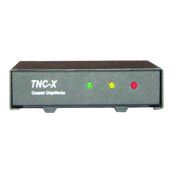
- Page 5 POWER Indicates the MFJ-1270X has power supply voltage supplied. RECEIVE DCD Indicates the MFJ-1270X is receiving a data packet signal from the radio. TRANSMIT PTT Indicates that the MFJ-1270X is transmitting data signal from the radio.
- Page 6 Pin 5 – No Connection Troubleshooting The MFJ-1270X is designed to give years of service. However, as with all things sometimes problems do come up and need to be taken care of. Here are a few troubleshooting tips in the event that something does go wrong.
- Page 7 Voltage Supply If the supply voltage is suspect this must be corrected first. The first thing to do is to check the main voltage supply to the TNC. Do this using a DC voltmeter ca- pable of measuring +5 volts DC. The main supply voltage to the TNC must be at least 7 to 8 volts DC.
- Page 8 +5 volts DC. If any IC causes the +5 volts DC to drop, then the IC that caus- es the voltage drop is your defective part. Be sure to check all IC chips, be- cause you could have more than one defective part. Call the MFJ Service Dept. for a replacement part.
- Page 9 XP, as well as older versions of Windows. If you want to use AGWPE, there is a link on the TNC-X webpage that contains detailed instructions. If you have any problems with any of this, please contact MFJ Technical Services at the phone number in the warranty instructions.
- Page 12 Parts List: Capacitors: 10 µF electrolytic 100 pF ceramic (marked 101J) C2, C4, C5, C6, C11, C14, C15, C16, C17, C18, C19, C20, C26 µ01 Multilayer (marked 103) C21, C22, C23, C25 µ1 monocap (small yellow - may be marked 104z) C7, C8 µ01 Polyproplene (red/yellow block) C9, C10...
- Page 13 Other Components 3.57 MHz Crystal (may be labeled A035) 20 MHz Crystal (may be labeled A200) 2N2222 or similar FT232RL USB interface chip CML614 Modem Chip - 16 pins FM25640 FRAM memory chip PIC16F628A or PIC16F648A MPC6023 OpAmp SP232A or HIN232A 78L05 Voltage Regulator DB9 Female PC mount Connector Coaxial Power Connector (Center Pin is Positive=...
- Page 14 X-DIGI TNC-X Digipeater Daughter Board Model MFJ-1270DG...
-
Page 15: Installation Instructions
Introdution X-Digi is a daughter board for the TNC-X KISS mode TNC. It is designed to emu- late the most popular features of the widely used UI-DIGI EEPROM for TNC-2s. In addition, X-Digi provides digipeater services for both UI APRS frames and for con- nected packets. - Page 16 for 9600 baud and no flow control. Turn on the TNC-X with the X-Digi daughter- board installed and within 20 seconds strike any key in the terminal program to get the X-Digi's attention. You should see the following menu: X-Digi Ver 2.0E Configuration Menu Set Digipeater callsign.
- Page 17 For example, if you wanted to support RELAY (not currently recommended) you could do so by adding this value in UICALL. Packets with a path of RELAY would be digipeated with a path of URCALL. The menu also allows you to specify a dupe time value in 5 second intervals.
- Page 18 stand alone unit, you can simply leave the jumpers in their "configuration" set- ting. X-Digi is designed to be field upgradeable. It has boot loader built in that allows you to upload new firmware if and when it becomes available. instructions on how to use the boot loader are available on a link from the TNC-X webpage http://www.tnc-x.com/firmware.htm.
- Page 19 x.com/XDiqi.htm) called calcpw.jar. The program was written in Java, so it should run on any platform and it is an executable .jar file so you should be able to run it simply by double-clicking on it. Of course you will need to have the Java run- time environment on your computer to run the program, but most computers these days already have this loaded.
- Page 20 X-Digi Ver 2.0E Configuration Menu Set Digipeater callsign. :URCALL Set Digipeater Alias. :URDIGI Set UIFlood callsign. Set UIFlood Limit. Set UITrace Callsign. :WIDE Set UITrace Limit. Set UICall 1. Set UICall 2. Set UICall 3. Set UICall 4. Set UICall 5. Set UICall 6.
- Page 21 want during a remote sysop session. The session will conclude in one of two ways. If you send the command: You should receive back the word “Done” and the X-DIGI will exit remote sysop mode. If 45 seconds passes and the X-DIGI does not receive a command, it will automatically reboot.
- Page 22 In the case of items 5 through 8 you must specify exactly 5 digits followed by 1 space and 3 digits. You can inquire about the value of a parameter form this page using the syntax: where is the parameter from the Beacons page that you want to ask about. All beacons are turned off during a remote SysOp session.
Need help?
Do you have a question about the MFJ-1270X and is the answer not in the manual?
Questions and answers