Advertisement
Installation and Assembly:
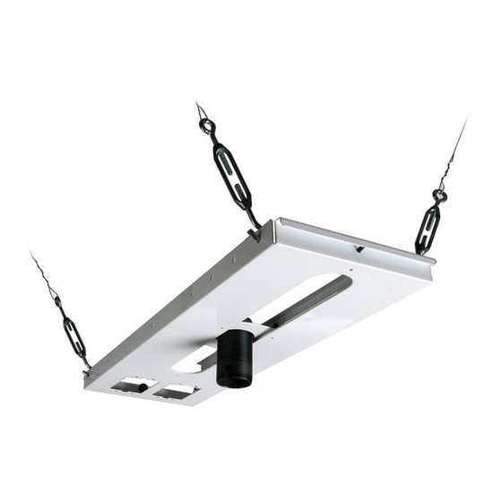
Adjustable Suspended Ceiling Channel Kit
Model: ELPMBP01
Manufactured by Peerless Industries, Inc.
3215 W. North Ave. • Melrose Park, IL 60160 • (800) 865-2112 or (708) 865-8870 • Fax: (708) 865-2941 • www.peerlessmounts.com
This product is UL Listed. It must be
installed by a qualified professional
R
installer.
Maximum UL Load Capacity:
50 lb (22.6 kg)
Advertisement
Table of Contents

Related Manuals for Epson ELPMBP01


Summary of Contents for Epson ELPMBP01
- Page 1 Installation and Assembly: Adjustable Suspended Ceiling Channel Kit Model: ELPMBP01 Manufactured by Peerless Industries, Inc. 3215 W. North Ave. • Melrose Park, IL 60160 • (800) 865-2112 or (708) 865-8870 • Fax: (708) 865-2941 • www.peerlessmounts.com This product is UL Listed. It must be installed by a qualified professional installer.
-
Page 2: Tools Needed For Assembly
NOTE: Read entire instruction sheet before you start installation and assembly. • Do not begin to install your product until you have read and understood the instructions and warnings contained in this Installation Sheet. If you have any questions regarding any of the instructions or warnings, call Peerless customer care at 1-800-729-0307. -
Page 3: Parts List
Before you start check the parts list to insure all of the parts shown are included. NOTE: You may not need all hardware provided. Parts List Description ceiling tray 1/4"-20 x 3/8" screws 1/4"-20 nuts allen wrench escutcheon ring turnbuckle 12 gauge x 20' (6.1m) tie wire (not shown) eye bolt concrete anchor... -
Page 4: Installation To Suspended Ceiling
Installation to Suspended Ceiling IMPORTANT PRE-ASSEMBLY INFORMATION: Ceiling Tray (A) is designed to fit above a 24" (610 mm) x 24" (610 mm) section of a conventional suspended ceiling system. It may also be mounted above 24" x 48" conventional suspended ceiling. Ceiling runners (see DETAIL 2, page 5) should have a “T”... -
Page 5: Anchoring Ceiling Plate
Anchoring Ceiling Plate Cut tie wire (G) into four pieces of equal length. Insert wires through ends of turnbuckles and loop. Twist each wire around itself at least six times. Drill holes for four ceiling anchors (see "Various Anchoring Methods"). Position the holes so that when the tie wires (G) are attached and taut will angle out at 15 Pull tie wires tight and loop though turnbuckles of the ceiling anchors (or truss). -
Page 6: Limited Five-Year Warranty
LIMITED FIVE-YEAR WARRANTY www.peerlessmounts.com © 2007 Peerless Industries, Inc. ISSUED 03/17/06 LIT-0190E 6 of 6 ISSUED: 02-13-08 SHEET #: 128-9029-2 07-10-08 Visit the Peerless Web Site at www.peerlessmounts.com For Technical Support Contact Peerless Mounts at 1-800-729-0307 or 708-865-8870. © 2008, Peerless Industries, Inc. All rights reserved. All other brand and product names are trademarks or registered trademarks of their respective owners.
Need help?
Do you have a question about the ELPMBP01 and is the answer not in the manual?
Questions and answers