HAMPTON BAY Hampton H300 Owners & Installation Manual
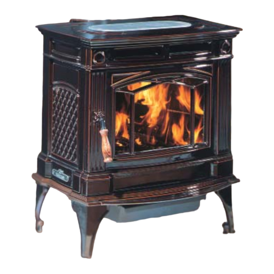
Freestanding woodstove
Hide thumbs
Also See for Hampton H300:
- Owners & installation manual (32 pages) ,
- Brochure & specs (16 pages) ,
- Owners & installation manual (36 pages)
Table of Contents
Advertisement
Owners &
Freestanding Woodstove
Installation Manual
www.hampton-fi re.com
MODEL:
H300
Tested by:
Installer: Please complete the details on the back cover
and leave this manual with the homeowner.
Homeowner: Please keep these instructions for future reference.
918-214d
10/25/11
FPI FIREPLACE PRODUCTS INTERNATIONAL LTD. 6988 Venture St., Delta, BC Canada, V4G 1H4
Advertisement
Table of Contents

Related Manuals for HAMPTON BAY Hampton H300


Summary of Contents for HAMPTON BAY Hampton H300
- Page 1 Tested by: Installer: Please complete the details on the back cover and leave this manual with the homeowner. Homeowner: Please keep these instructions for future reference. 918-214d 10/25/11 FPI FIREPLACE PRODUCTS INTERNATIONAL LTD. 6988 Venture St., Delta, BC Canada, V4G 1H4...
- Page 2 Thank-you for purchasing a HAMPTON FIREPLACE PRODUCT. The pride of workmanship that goes into each of our products will give you years of trouble-free enjoyment. Should you have any questions about your product that are not covered in this manual, please contact the HAMPTON DEALER in your area.
-
Page 3: Table Of Contents
TABLE OF CONTENTS SAFETY LABEL OPERATING INSTRUCTIONS Copy of Safety Label for H300 ........4 Operating Instructions ..........23 Fan Operation..............23 First Fire ..............23 INSTALLATION Safety Guidelines and Warnings .........24 Draft Control ..............24 Unit Dimensions with Standard Legs......5 Ash Disposal..............25 Unit Dimensions with Optional Short Legs ....6 Creosote ..............26 Pre-installation Assembly ..........7 Glass Maintenance ............26... -
Page 4: Safety Label
MODEL S2100 OR MODEL ASHT, SELKIRK MODEL SSII, OLIVER MACLEOD PRO JET 3103, SIMPSON DURA PLUS, GSW MODEL SC OR METAL-FAB TEMP/GUARD, AMERI-TECHS, ICC EXCEL 2100 . USE CHIMNEY COMPONENTS AS SPECIFIED IN INSTALLATION INSTRUCTIONS. MANUFACTURED BY: FPI FIREPLACE PRODUCTS INTERNATIONAL LTD. 6988 VENTURE ST. DELTA, BC V4G 1H4... -
Page 5: Unit Dimensions With Standard Legs
DIMENSIONS UNIT DIMENSIONS WITH STANDARD LEGS Hampton H300 Cast Freestanding Woodstove... -
Page 6: Unit Dimensions With Optional Short Legs
DIMENSIONS UNIT DIMENSIONS WITH OPTIONAL SHORT LEGS Hampton H300 Cast Freestanding Woodstove... -
Page 7: Pre-Installation Assembly
INSTALLATION Rotating Elbow PRE-INSTALLATION Side Load Door Handle ASSEMBLY This stove can be connected to either a top or rear vent exit by simply reversing the orientation 1) To install side door handle, remove side of the elbow. door plug assembly. After removing the stove from its packing, open the front door and remove the contents from the Simply remove the 2 screws, change the posi-... -
Page 8: Residential Installation
INSTALLATION even reduced heat output. Too tall a chimney 10) In seismically active areas, we recommend RESIDENTIAL may prompt excessive draft which can result that your unit is secured to the fl oor by using INSTALLATION in very short burn times and excessive heat the bolt down holes inside the legs (the same ones used in Mobile Home installations). -
Page 9: Minimum Clearance To Combustible Materials
INSTALLATION MINIMUM CLEARANCE TO COMBUSTIBLE MATERIALS Please read the section below carefully. Measurements "From Unit" are from the top plate of the stove to a side wall or to a corner, and from the rear heat shield to a back wall. Clearances may only be reduced by means approved by the regulatory authority. -
Page 10: Minimum Alcove Clearance To Combustible Materials
INSTALLATION MINIMUM ALCOVE CLEARANCE TO COMBUSTIBLE MATERIALS This Hampton Freestanding model has been alcove approved and must be installed with a listed double wall connector to the ceiling level. Note: Minimum alcove ceiling height (from fi nished fl oor) - 60" (1525 mm) Maximum depth of alcove - 48"... -
Page 11: Floor Protection
INSTALLATION FLOOR PROTECTION A combustible fl oor must be protected by non-combustible material (like tile, concrete board, or certifi ed to UL-1618 or as defi ned by local codes) extending beneath the heater and a minimum of 6" from each side and minimum 18" from the front face of the stove and minimum 6" (or the rear clearance to combustibles whichever is smaller) from the rear of the stove. -
Page 12: How To Determine If Alternate Floor Protection Materials Are Acceptable
INSTALLATION 1) With your location already established, cut The diagrams below illustrate one way to in- HOW TO DETERMINE IF and frame the roof hole. It is recommended stall your unit into a standard ceiling or with a ALTERNATE that no ceiling support member be cut for horizontal connector. -
Page 13: Masonry Chimney
INSTALLATION MASONRY CHIMNEY Ensure that a masonry chimney meets the minimum standards of the National Fire Protection Association (NFPA) by having it inspected by a professional. Make sure there are no cracks, loose mortar or other signs of deterioration and blockage. Have the chimney cleaned before the stove is installed and operated. -
Page 14: Combustible Wall Chimney Connector Pass-Throughs
INSTALLATION COMBUSTIBLE WALL CHIMNEY CONNECTOR PASS-THROUGHS Method A: 12" (304.8 mm) Clearance to Combustible Wall Minimum chimney clearance to brick and combustibles 2 in. (50.8mm) Member: Using a minimum thickness 3.5" (89 mm) brick and a 5/8" (15.9 mm) Minimum clearance minimum wall thickness clay liner, construct a wall pass-through. -
Page 15: Recommended Heights For Woodstove Flue
INSTALLATION RECOMMENDED HEIGHTS FOR WOODSTOVE FLUE Simple rules on draft. See Table 1. Example: a) Recommended Flue Height 1-1/2 ft. of horizontal run = 3 ft. Elevation Example a) Example b) 1) At sea level minimum height is 12' one "T" = 3 ft. -
Page 16: Mobile Home Installation
INSTALLATION MOBILE HOME INSTALLATION In addition to standard installation instructions Once you have properly marked the position the following requirements are mandatory for of your unit and the fl oor protection as outlined installation in a mobile home. in the Residential Installation items #1 through #8, a supply of fresh air has to be supplied to 1) The stove must be permanently bolted to your unit. -
Page 17: Listed Components For Mobile Home Installation
INSTALLATION LISTED COMPONENTS FOR MOBILE HOME INSTALLATION The Hampton H300 Cast Freestanding unit is approved for installation in a Mobile Home if one of the following pipe systems is used. U.S. Installation* AMERI-TECHS Canadian Installations* Qty.Part # Description 6DCC Connector METALBESTOS SSII SECURITY S2100 (see above for details) 6HSRS-12 Roof Support (6PLRS-12-... -
Page 18: Brick Installation
INSTALLATION BRICK INSTALLATION GLASS INSTALLATION DOOR REMOVAL Firebrick is included to extend the life of your 1) Remove door from unit. stove and to radiate heat more evenly. Check 1) Push spring lever down while holding onto to see that all fi rebricks are in their correct 2) To replace the glass remove the 12 screws the door. -
Page 19: Optional Short Leg Installation
INSTALLATION OPTIONAL SHORT LEG INSTALLATION 1) Remove the cast lid from the top of the stove. 8) Flip the cover plate so that the ash plug hole is covered. Secure the cover plate in place using the 6 bolts and washers removed in step 7. 2) Remove fan, if installed. - Page 20 INSTALLATION 10) Secure the 4 short legs to the unit using the bolts and washers 11) Carefully bring stove to standing position. removed from step 9. 12) Open the front door and place the cast plug into the ash plug hole and re-install the bricks.
-
Page 21: Optional Blower / Fan Installation
INSTALLATION OPTIONAL BLOWER / FAN INSTALLATION An optional blower is available for the Hampton 1) Lift off top. 5) Remove fan cover plate from back shield H300. The blower is factory assembled, wired by undoing 3 screws. and ready for attachment to the stove. 2) Place left and right side air channels on fi... -
Page 22: Side Shelf Installation
INSTALLATION SIDE SHELF INSTALLATION 1) Secure the two support gussets using 2 screws per gusset and attach 3) Secure to side shelf to stove. Repeat installation for other side. bracket to the underside of the shelf using 2 screws as shown. Support Gussets Bracket... -
Page 23: Operating Instructions
OPERATING INSTRUCTIONS INSTALLATION 13) All fuel burning appliances consume oxygen 3) With the draft still in the fully open position OPERATING add two or three seasoned logs to your fi re. during operation. It is important that you INSTRUCTIONS Form a trench in the ash bed to allow air to supply a source of fresh air to your unit reach the rear of the fi... -
Page 24: Safety Guidelines And Warnings
OPERATING INSTRUCTIONS 13) Your woodstove should burn dry, standard SAFETY GUIDELINES DRAFT CONTROL fi rewood only. The use of cut lumber, ply- AND WARNINGS wood, “mill ends”, etc. is not allowed as this Both the primary and air wash drafts are control- fuel can easily overheat your woodstove. -
Page 25: Ash Disposal
OPERATING INSTRUCTIONS INSTALLATION ASH DISPOSAL Ash Drawer Operating Guideline 1) Only clean ashes out of the stove when the During constant use, ashes should be removed unit has cooled down. Remove the plug by every few days. The Ash Drawer features a lifting on the handle using the tool provided. -
Page 26: Creosote
MAINTENANCE WOOD STORAGE MAINTENANCE CREOSOTE Store wood under cover, such as in a shed, or It is very important to carefully maintain your When wood is burned slowly, it produces tar and covered with a tarp, plastic, tar paper, sheets stove, including burning seasoned wood and other organic vapours, which when combined maintaining a clean stove and chimney system. -
Page 27: Front Door Gasket
MAINTENANCE FRONT DOOR GASKET If position of bracketry needs to be changed after adjustment: If the front door gasket requires replacement The bracketry should start from the highest point, 5/8" diameter material must be used. Hampton as seen below. If needed, bring the bracketry uses a 5/8"... -
Page 28: Top Baffl E Replacement
MAINTENANCE TOP BAFFLE REPLACEMENT 3) Remove the left and right baffl e caps by removing the 2 bolts (7/16) 1) Lift the Top Hob off the top of the stove. socket 1/4-20 x 1/2" hex head on each side and lift out. Top Hob 4) Remove the three (7/16) socket 1/4-20 x 1/2"... -
Page 29: Annual Maintenance
MAINTENANCE Annual Maintenance Completely clean out entire unit Annually Inspect air tubes, baffl es and bricks Replace any damaged parts. Adjust door catch / latch If unable to obtain a tight seal on the door - replace door gasket seal. Readjust latch after new gasket installed. -
Page 30: Parts List
PARTS LIST PARTS LIST H300 MAIN ASSEMBLY Part # Description Part # Description 220-160 Grill Cast - Top 26) 220-110 Firebox Cast - Front 27) 220-090 Latch Bar 220-371 Stove Top - Charcoal Grey 220-374 Stove Top - Ivory 28) 220-331 Front Skirt - Charcoal Grey 220-334 Front Skirt - Ivory... - Page 31 PARTS LIST PARTS LIST Hampton H300 Cast Freestanding Woodstove...
-
Page 32: H300 Door Assembly
PARTS LIST PARTS LIST H300 DOOR ASSEMBLY Part # Description 70) 846-530 5/8" Door Gasket Kit 71) 220-034F Retention Glass Top 72) 220-035F Retention Glass 73) 936-243 7/8" Window Adhesive Tape 74) 940-333/P Neoceram Flush Glass c/w Gasket 75) 220-441 Door &... -
Page 33: H300 Firebrick
PARTS LIST PARTS LIST H300 FIREBRICK Part # Description 220-960 Firebrick Set 90) 802-157 Brick Partial - 4.5" x 8.5" 91) 802-148 Brick Partial - 4.5" x 4.5" 92) 802-158 Brick Partial - 2" x 8.5" 93) 802-159 Brick Partial - 4.5" x 8.5" (cut angle) 94) 802-160 Brick Partial - 2.25"... - Page 34 NOTES Hampton H300 Cast Freestanding Woodstove...
-
Page 35: Warranty
At no time will FPI be liable for any consequential damages which exceed the purchase price of the unit. FPI has no obligation to enhance or modify any unit once manufactured. ie. as products evolve, fi eld modifi cations or upgrades will not be performed. - Page 36 Dealer Name & Address: ______________________________________________ ___________________________________________________________________ Installer: ___________________________________________________________ Phone #: ___________________________________________________________ Date Installed: ______________________________________________________ Serial No.: __________________________________________________________ Hampton is a trademark of FPI Fireplace Products International Ltd. Printed in Canada © Copyright 2011, FPI Fireplace Products International Ltd. All rights reserved.
Need help?
Do you have a question about the Hampton H300 and is the answer not in the manual?
Questions and answers
how to replace left side fire brick
The provided context does not include specific instructions for replacing the left side fire brick on a Hampton Bay H300. However, general firebrick replacement steps typically involve:
1. Ensuring the stove is cool and clean.
2. Removing any parts obstructing access to the firebricks.
3. Carefully taking out the damaged or worn firebrick.
4. Placing the new firebrick in the correct position, ensuring it fits securely.
5. Reassembling any removed parts.
For exact instructions, refer to the stove’s manual or contact a Hampton dealer.
This answer is automatically generated