Table of Contents
Advertisement
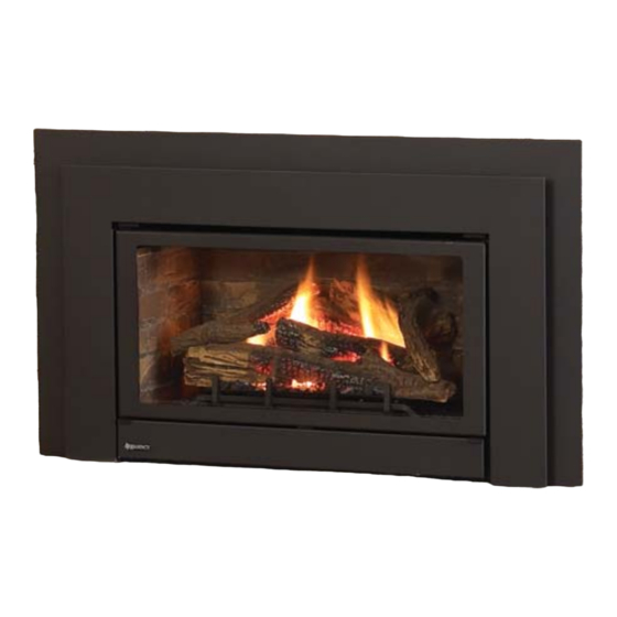
U32E Gas Insert
WARNING:
Improper installation, adjustment, alteration, service or
maintenance can cause injury or property damage. Refer to
this manual. For assistance or additional information consult
an authorized installer, service agency or the gas supplier.
FOR YOUR SAFETY
Do not store or use gasoline or other fl ammable vapours and
liquids in the vicinity of this or any other appliance.
Installation and service must be performed by an authorized
installer, service agency or the gas supplier.
Tested by:
918-846c
MODELS: U32E-NG5 Natural Gas U32E-LP5 Propane
Installer: Please complete the details on the back cover
and leave this manual with the homeowner.
Homeowner: Please keep these instructions for future reference.
FPI FIREPLACE PRODUCTS INTERNATIONAL LTD. 6988 Venture St., Delta, BC Canada, V4G 1H4
Owners &
Installation Manual
www.regency-fi re.com
FOR YOUR SAFETY
What to do if you smell gas:
Do not try to light any appliance
Do not touch any electrical switch:
do not use any phone in your
building.
Immediately call your gas supplier
from a neighbour's phone. Follow
the gas supplier's instructions.
If you
cannot reach your gas
supplier, call the fi re department.
07/12/12
Advertisement
Table of Contents

Related Manuals for Regency U32E-NG5


Summary of Contents for Regency U32E-NG5
- Page 1 Owners & U32E Gas Insert Installation Manual www.regency-fi re.com MODELS: U32E-NG5 Natural Gas U32E-LP5 Propane WARNING: FOR YOUR SAFETY Improper installation, adjustment, alteration, service or What to do if you smell gas: maintenance can cause injury or property damage. Refer to Do not try to light any appliance this manual.
- Page 2 TO THE NEW OWNER Congratulations! You are the owner of a state-of-the-art Gas Insert by FPI. The FPI Gas Insert Series of hand crafted appliances has been designed to provide you with all the warmth and charm of a fi replace, at the fl ick of a switch. The models U32E-NG5 and U32E-LP5 of this series have been approved by Warnock Hersey for both safety and effi...
- Page 3 DIMENSIONS 40-1/4" 1-3/8" 10-3/4" 13-3/4" 28" Note: Oversize faceplate is 44" x 28" 40-3/4” (1036mm) 7/8” 35-15/16” (912mm) (22mm) 9-15/16” (252mm) 27-7/8” (708mm) Low Profi le Faceplate Dimensions INFORMATION FOR MOBILE/MANUFACTURED HOMES AFTER FIRST SALE This FPI product has been tested and listed by Warnock Hersey as a Direct Vent Wall Furnace to the following standards: CAN/ CGA-2.17-M91, and ANSI Z21.88-2009/CSA 2.33-2009.
-
Page 4: Table Of Contents
Gas Pipe Pressure Testing .......... 11 Gas Insert Aeration System ......... 11 Optional Brick Panel ............ 11 Log Set Installation ............12 Regency Faceplate & Trim Installation ......16 Standard Flush Door ...........17 Flush Louvers ..............17 Conversion from NG to LP ..........18 Full Screen doors ............19... -
Page 5: Safety Label
SAFETY LABEL This is a copy of the labels that accompany each U32E-5 Gas Insert. NOTE: FPI units are constantly being improved. Check the label We have printed a copy of the contents here for your review. The safety on the unit and if there is a difference, the label on the unit is the label is located on a plate inside the base of the unit visible when the correct one. -
Page 6: Requirements
REQUIREMENTS REQUIREMENTS MA Code - CO Detector (for the State of Massachusetts only) 5.08: Modifications to NFPA-54, Chapter 10 (2) Revise 10.8.3 by adding the following additional requirements: (a) For all side wall horizontally vented gas fueled equipment installed in every dwelling, building or structure used in whole or in part for residential purposes, including those owned or operated by the Commonwealth and where the side wall exhaust vent termination is less than seven (7) feet above finished grade in the area of the venting, including but not limited to decks and porches, the following requirements shall be satisfied:... -
Page 7: Installation
INSTALLATION INSTALLATION IMPORTANT MESSAGE YOUNG CHILDREN SHOULD BE CARE- FULLY SUPERVISED WHEN THEY ARE SAVE THESE IN THE SAME AREA AS THE APPLI- INSTRUCTIONS ANCE. TODDLERS, YOUNG CHILDREN AND OTHERS MAY BE SUSCEPTIBLE The U32E-5 Gas Insert must be installed in TO ACCIDENTAL CONTACT BURNS. -
Page 8: Important Message
INSTALLATION IMPORTANT MESSAGE GAS PRESSURE General Safety Information SAVE THESE TESTING 1) The appliance installation must conform INSTRUCTIONS with local codes or in the absence of local The appliance must be isolated from the gas sup- codes, with CAN/CGA B149 (in Canada) or ply piping system by closing its individual manual The FPI Gas Insert must be installed in the National Fuel Gas Code ANSI Z223.1 in... -
Page 9: Installation Checklist
Width Width ensure that the fl ame does not carbon. Bar Depth Height Depth (rear) (front) See "Gas Insert Aeration System" Flush section. Regency 9" 22" 14" 22-1/2" 26-1/2" with Contour c) Ensuring that the appliance is venting Faceplate Floor correctly. -
Page 10: Gas Connection
INSTALLATION VENTING The Air Intake pipe must be attached to the inlet air collar of the termination cap. THE APPLIANCE MUST NOT BE CONNECTED TO A CHIMNEY FLUE SERVING A SEPARATE SOLID FUEL BURNING APPLIANCE. This appliance is designed to be attached to two 3"... -
Page 11: Venting
INSTALLATION 1) Make sure the valve is in the "OFF" OPTIONAL position. BRICK PANEL 2) Loosen the "IN" and/or "OUT" pressure tap(s), turning counterclockwise with a 1/8" 1) Unwrap the brick pattern panels from the wide fl at screwdriver. protective wrapping. 3) Attach manometer to "IN"... -
Page 12: Log Set Installation
INSTALLATION LOG SET INSTALLATION Read the instructions below carefully and refer to the images. 2) Spread vermiculite around the exposed fi rebox base. Then take some Dangerous operating conditions may occur if the logs are not embers and spread them over the vermiculite as shown. positioned in their correct locations. - Page 13 INSTALLATION 6) Fit the groove in log 27-34 into the tab on the right side of the burner. Rest the other end of log 27-34 on the notch in log 27-33. 27-32 27-34 5) Fit log 27-33 into the pins at the front of the burner. 27-33 27-34 27-33...
- Page 14 INSTALLATION 9) Place embers along the front of the burner as shown. Ensure not to cover any burner ports. 27-35 Embers 8) Fit log 27-36 into the pins on logs 27-33 and 27-31. 10) Separate platinum embers and place on the burner just in front of the logs as shown.
- Page 15 INSTALLATION Completed Log Set Installation 27-34 27-31 27-35 27-32 27-36 27-33 U32E-5 FPI Direct Vent Gas Insert...
-
Page 16: Regency Faceplate & Trim Installation
INSTALLATION REGENCY FACEPLATE & TRIM INSTALLATION 1) Lay the faceplate panels fl at, face down on 9) Attach the brass trim to the faceplate by drilling something soft so they don't scratch. a 1/8" hole through into the faceplate using the hole in the trim as a guide. -
Page 17: Standard Flush Door
INSTALLATION STANDARD Use the hook to pull the spring out until you can 2) Install the Spring Hinges on the left and right put the hook into the slot on the bottom door side of the bottom of the Firebox using 2 FLUSH DOOR bracket. -
Page 18: Conversion From Ng To Lp
INSTALLATION CONVERSION FROM NG TO LP For U32E-5 Using SIT 886 NOVA Gas Valve THIS CONVERSION MUST BE DONE BY A QUALIFIED GAS FITTER IF IN DOUBT DO NOT DO THIS CONVERSION !! Remove burner orifi ce with a 1/2" 3b) Remove the Burner Tray by removing Each Kit contains one LPG wrench. -
Page 19: Full Screen Doors
INSTALLATION FULL SCREEN DOORS 1) Hold the full screen door frame up against the unit in order to make 3) Completely secure the full screen door frame to the unit by securing 4 screws to the Left and Right Side Trims. the following wire connections. - Page 20 INSTALLATION 4) Install Spring Hinges on the Left and Right Side of the bottom of the 7) Install the Left and Right Side Screen Doors in the fully open position fi rebox using 2 screws per hinge. by placing over top of the hinges on the full screen door frame. Hinge 5) Place Bottom Frame near hinge.
-
Page 21: Contemporary Faceplate And Doorframe Installation
INSTALLATION CONTEMPORARY FACEPLATE AND DOORFRAME INSTALLATION Kit# 425-914 Contents List: Note: Ensure that the fl anges on the sides of the fi rebox are on the outside, when installing the faceplate (see below). Complete Faceplate with Switches Door Frame Bottom Louver Hinges Bottom Louver Brackets Pan Head Screws... - Page 22 INSTALLATION 7) Install the door frame by hooking the top fl ange over the top of the glass door. 8) Lower the door frame gently into place. 9) Run supplied 120V power cord along front face of masonry fi replace and plug into nearest receptacle. 10) Slide unit into fi...
-
Page 23: Optional Hearth Trim Installation
INSTALLATION OPTIONAL HEARTH TRIM INSTALLATION The Hearth Trim is an option that can be used to fi nish off the installation when the bottom of the fi replace is higher than the hearth or to raise the fi replace. The faceplate is assembled fi rst and then the hearth trim is attached to the faceplate. -
Page 24: Low Profi Le Faceplate Installation
INSTALLATION LOW PROFILE FACEPLATE INSTALLATION Attach the inner faceplate panel to the insert body using 4 screws 4) Tuck the wires into the clip to keep them away from the insert using in the locations shown below. the clip provided. Attach the clip to the rear of the faceplate to en- sure that the wires do not touch the side of the unit. - Page 25 INSTALLATION 10) Take the outer faceplate, line up the openings on the left and righ Attach the bottom louver to the 2 hinges using 2 screws per legs and install onto the inner faceplate panel pins. hinge. Diagram 7 Inner faceplate Install the top door pressure retainer, required.
-
Page 26: Low Profi Le Hearth Trim Installation
INSTALLATION LOW PROFILE HEARTH TRIM INSTALLATION Hearth Trim is an option that can be used to fi nish off the installation when the bottom of the fi replace is higher than the hearth or to raise the fi replace. ** If no screw holes are present. 1) For units L390E/HZI390E/L540E/HZI540E–remove 4 screws in locations shown below to remove outer faceplate. -
Page 27: Optional Wall Thermostat
INSTALLATION OPTIONAL WALL OPTIONAL REMOTE FINAL CHECK THERMOSTAT CONTROL Before leaving this unit with the customer, the installer must ensure that the appliance is fi ring A wall thermostat may be installed if desired, Use the FPI Remote Control Kit approved for correctly. -
Page 28: Gt Remote Installation
INSTALLATION GT REMOTE INSTALLATION 1) Shut off the gas supply and disconnect all power to the unit. 8) Plug in receiver DC supply wire to the DFC supply- as shown below. 2) Remove the louvers, bay door or faceplate if installed. 3) Disconnect battery pack - located on the fl... -
Page 29: Gtm Remote Installation
INSTALLATION GTM REMOTE INSTALLATION 6) Locate green and white ON/OFF wires. 1) Shut off the gas supply and disconnect all power to the unit. Connect the TPTH and TH wires - green to green and white to white as shown below. 2) Remove the louvers, bay door or faceplate, if installed. - Page 30 INSTALLATION 10) Install 4 - AA batteries into the receiver. 13) Reinstall the DFC box onto the velcro pad on the fl oor of the unit. Ensure correct polarity. 14) Install the heat shield to the receiver with two screws and attach to the fl...
-
Page 31: Wiring Diagrams
INSTALLATION WIRING DIAGRAMS This heater does not require a 120V A.C. supply for operation. In case of a power failure, the burner switch and the optional remote control/ thermostat will continue to operate. However, a 120V A.C. power supply is needed for the fan/blower operation. Caution: Ensure that the wires do not touch any hot surfaces and are away from sharp edges. -
Page 32: Operating Instructions
OPERATING INSTRUCTIONS OPERATING INSTRUCTIONS LIGHTING COPY OF LIGHTING INSTRUCTION PLATE PROCEDURE IMPORTANT To ignite or reignite the pilot, you must fi rst remove the glass door. FOR YOUR SAFETY READ BEFORE LIGHTING This appliance must be installed in accordance with local codes, if any; 1) Press and release on ON/OFF button once if none, follow the National Fuel Gas Code, ANSI Z223.1/NFPA 54, or Natural Gas and Propane Installation Codes, CSA B149.1. -
Page 33: Operating Instructions
OPERATING INSTRUCTIONS INSTALLATION FIRST FIRE OPERATING AUTOMATIC INSTRUCTIONS CONVECTION FAN The fi rst fi re in your stove is part of the paint curing process. To ensure that the paint is properly cured, OPERATION Before operating this appliance, proceed through it is recommended that you burn your fi... -
Page 34: Normal Operating Sounds Of Gas Appliances
OPERATING INSTRUCTIONS MAINTENANCE NORMAL OPERATING WARNING: CHILDREN AND ADULTS SOUNDS OF INSTRUCTIONS SHOULD BE ALERTED TO THE HAZARDS OF HIGH SURFACE GAS APPLIANCES 1) Always turn the gas valve to off before TEMPERATURE AND SHOULD STAY cleaning. For relighting, refer to lighting AWAY TO AVOID BURNS OR CLOTHING It is possible that you will hear some sounds instructions. -
Page 35: Pilot Adjustment
3) Check for evidences of excessive Note: If you have an incorrect fl ame pattern, all authorized dealers. Do not use abrasive condensation, such as water droplets forming contact your Regency ® dealer for materials. Do not clean the glass when hot. -
Page 36: Fan Maintenance
MAINTENANCE MAINTENANCE Bay Glass Removal 10) Unplug the wires from the fan motor (from TO REMOVE FAN: inside the stove). 1) Turn the unit off and allow it to cool to room 1) Remove the door from the unit and place temperature. -
Page 37: Valve Replacement
MAINTENANCE VALVE REPLACEMENT 10) Remove the 11 screws securing the valve tray in place - then lift the entire assembly out. 1) Shut off the gas supply. 2) Remove the louvers (and bay door if installed). 3) Open the fl ush door and remove the door. 4) Remove the logs and brick panels. -
Page 38: Parts List
PARTS LIST PARTS LIST MAIN ASSEMBLY Part # Description Part # Description 1) 420-122 Fan Access Panel 46) * Adaptor Holding Brkt-Left 2) 420-142 Gasket - Fan Access Panel 47) * Adaptor Holding Brkt-Right 422-518/P Fan Assembly: 48) 320-518 Flue Adaptor Assy 3) 910-215/P Fan Motor (120 V) 50) *... -
Page 39: Burner Assembly
PARTS LIST BURNER ASSEMBLY Part # Description 423-574E/P Valve Assembly - NG 423-576E/P Valve Assembly - LP 52) 911-004 Valve - SIT NG 911-005 Valve - SIT LP 55) * Valve Tray 58) 904-240 Burner Orifi ce Nat. Gas #37 904-390 Burner Orifi... -
Page 40: Bay & Flush Front Assembly
PARTS LIST FLUSH FRONT ASSEMBLY Part # Description Flush Door 422-530 Complete Flush Door Assy 112) 904-196 1" Round Magnet 135) 940-307/P Flush Glass 137) 904-691 U Clip 139) 936-155 Tadpole Glass Gasket FLUSH FRONT U32E-5 FPI Direct Vent Gas Insert... -
Page 41: Faceplate Assembly
2-way Gold Contact Switch 191) * Screw #8 x 1/2" Brass self-tapping ® 98) 910-330 Fan Speed Control (120 V) 199) 948-216 Regency Logo Plate 99) 904-569 Fan Speed Control Knob (120 V) *Not available as a replacement part. 400-917... -
Page 42: Contemporary Faceplate And Door Frame
PARTS LIST CONTEMPORARY FACEPLATE AND DOOR FRAME Part # Description 1) 425-512 Door Bottom Assembly 2) 425-513 Frame Inside 3) 425-514 Faceplate Outside 4) 425-942 Hearth Trim U32E-5 FPI Direct Vent Gas Insert... -
Page 43: Low Profi Le Faceplate
PARTS LIST LOW PROFILE FACEPLATE Part # Description Backplate Assembly Bottom Louver Right mounting bracket Left mounting bracket Front Frame U32E-5 FPI Direct Vent Gas Insert... - Page 44 NOTES U32E-5 FPI Direct Vent Gas Insert...
- Page 45 NOTES U32E-5 FPI Direct Vent Gas Insert...
- Page 46 NOTES U32E-5 FPI Direct Vent Gas Insert...
- Page 47 It is the general practice of FPI to charge for larger, higher priced replacement parts and issue credit once the replaced component has been returned to FPI and evaluated for manufacturer defect. The authorized selling dealer is responsible for all in-fi eld service work carried out on your Regency product. FPI will not be liable for results or costs of workmanship from unauthorized service persons or dealers.
- Page 48 ® Register your Regency warranty online www.regency-fi re.com Reasons to register your product online today! • View and modify a list of all your registered products. • Request automatic email notifi cation of new product updates. • Stay informed about the current promotions, events, and special offers on related products.
Need help?
Do you have a question about the U32E-NG5 and is the answer not in the manual?
Questions and answers