Table of Contents
Advertisement
Quick Links
Download this manual
See also:
Owner's Manual
the model g0634z is the same machine as the model g0634 except it has a different type of spiral
cutterhead. except for the differences noted in this insert, all other content in the model g0633/g0634
owner's manual applies to this machine. before operating your new machine, you must read and under-
stand this insert and the entire model g0633/g0634 manual to reduce the risk of injury when using this
machine.
If you have any further questions about this manual insert or the differences between the Model G0634Z
and the Model G0633/G0634, contact our Technical Support at (570) 546-9663 or email techsupport@
grizzly.com.
machine inventory
refer to the inventory in the g0633/g0634
manual on page 14. after all the parts have been
removed from the crate, you should have the fol-
lowing items:
common components (figure 1)
a. Jointer/planer assembly (not shown) ........ 1
b. push blocks ................................................ 2
c. Cutterhead guard assembly ...................... 1
d. hardware and tools (not shown)
— wrench 12/14mm ................................... 1
— hex wrench 3mm .................................. 1
b
figure 1. Common components.
Warning: no portion of this manual may be reproduced in any shape
or form Without the Written approval of grizzly industrial, inc.
(For models manuFaCtured sinCe 5/09) #bl12040 printed in taiwan
Qty
C
Copyright © september, 2009 by grizzly industrial, inC.
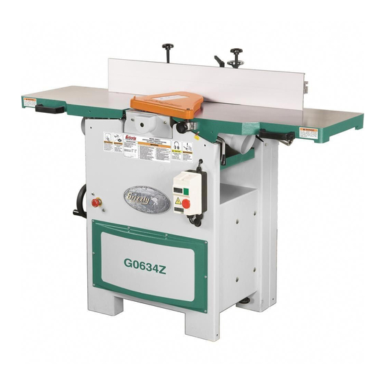
model g0634z
Jointer/planer
combination machine W/
spiral cutterhead
manual insert
g0634z only (figure
g. spiral Cutterhead hardware
—indexable Carbide inserts....................... 5
—Flat head torx screws 10-32 x
—torx drivers t25 ..................................... 5
—t-handle wrench
figure 2. spiral cutterhead hardware.
2
)
⁄
" ....... 10
1
2
/
" .............................. 1
1
4
g
Advertisement
Table of Contents

Related Manuals for Grizzly G0634Z


Summary of Contents for Grizzly G0634Z
- Page 1 1. Common components. Copyright © september, 2009 by grizzly industrial, inC. Warning: no portion of this manual may be reproduced in any shape or form Without the Written approval of grizzly industrial, inc. (For models manuFaCtured sinCe 5/09) #bl12040 printed in taiwan...
- Page 2 55 inch/ pounds. note: Excess oil may squeeze between the insert and cutterhead, thereby lifting the insert slightly and affecting workpiece finishes. model g0634z manual insert (mfg. 5/09+)
-
Page 3: Machine Data
MACHINE DATA SHEET MODEL G0634Z JOINTER/PLANER COMBINATION MACHINE W/SPIRAL CUTTERHEAD Product Dimensions: Shipping Dimensions: Electrical: Motors: Main Main Specifications: Fence Information Cutting Capacities (Jointer) Model G0634Z Page 1 of 2 model g0634z manual insert (mfg. 5/09+) - Page 4 Cutting Capacities (Planer) Cutterhead Information Table Information (Jointer) Table Information (Planer) Construction Other Infomation Other Specifications: Features: Model G0634Z Page 2 of 2 model g0634z manual insert (mfg. 5/09+)
-
Page 5: Stand Assembly
(mfg. 5/09+) - Page 6 P0633014-1 SWITCH KNOB PWR1214 WRENCH 12 X14 P0633015 EMERGENCY STOP SWITCH CORD PAW03M HEX WRENCH 3MM P0633016 KNOB BOLT 3/8-16 P0633043 SPECIAL SCREW 5/16-18 X 1-1/2 P0633017 STRAIN RELIEF P0633044 KNOB 1/4-20 X 1/2 model g0634z manual insert (mfg. 5/09+)
-
Page 7: Table Assembly
PLATE PB07 HEX BOLT 5/16-18 X 3/4 135-8 P0633215-8 PLATE P0633118 KNOB SCREW 1/4-20 X 1 PS01 PHLP HD SCR 10-24 X 1/2 PS18 PHLP HD SCR 10-24 X 1/4 PN07 HEX NUT 10-24 model g0634z manual insert (mfg. 5/09+) - Page 8 & motor model g0634z manual insert (mfg. 5/09+)
- Page 9 CAP SCREW 5/16-18 X 3-1/4 P0633216 MOTOR PULLEY PSS03 SET SCREW 1/4-20 X 3/8 217V2 P0633217V2 PULLEY V2.01.08 PS06 PHLP HD SCR 10-24 X 3/8 P0633218 ROLLER SUPPORT BLOCK PW03 FLAT WASHER #10 P0633219 ANTIKICKBACK FINGER model g0634z manual insert (mfg. 5/09+)
- Page 10 CAP SCREW 5/16-18 X 3/4 P0633317 ROLL PIN PLN01 LOCK NUT 3/8-16 P0633318 SPACER PCAP12 CAP SCREW 5/16-18 X 2-1/2 P0633319 SPROCKET 19T PLW01 LOCK WASHER 5/16 PR57M INT RETAINING RING 22MM P0633113 PLASTIC KNOB -10- model g0634z manual insert (mfg. 5/09+)
- Page 11 SET SCREW 3/8-16 X 2 P0633415 UNIVERSAL LOCK LEVER PS35 PHLP HD SCR 5/16-18 X 3/4 P0633417 ROLL PIN P0633437 HANDLE P0633418 THRUST BEARING NTB1528 +2AS P0633438 SPECIAL SCREW 3/8-16 X 3-3/8 PR79M INT RETAINING RING 19MM -11- model g0634z manual insert (mfg. 5/09+)
- Page 12 CAP SCREW 10-24 X 1-1/4 P0633504 SWITCH ACTIVATION ROD PCAP06 CAP SCREW 1/4-20 X 1 P0633505 SWITCH ACTIVATION ROD P0633514 LIMIT SWITCH P0633506 SWITCH ACTIVATION ROD P0633515 LIMIT SWITCH CONTROL CORD PLN03 LOCK NUT 5/16-18 -12- model g0634z manual insert (mfg. 5/09+)
- Page 13 -13- model g0634z manual insert (mfg. 5/09+)
- Page 14 ROLL PIN 5 X 30 PFH19 FLAT HD SCR 1/4-20 X 3/8 P0633705 TORSION SPRING P0633625 TUBE LOCKING SHOE PR48M EXT RETAINING RING 11MM P0633626 UNIVERSAL LOCK LEVER P0633710 LOAD WASHER P0633627 UNIVERSAL LOCK LEVER -14- model g0634z manual insert (mfg. 5/09+)
- Page 15 (800) 523-4777 or www.grizzly.com to order new labels. -15-...
- Page 16 ® h7194—bifocal safety glasses 1.5 h7195—bifocal safety glasses 2.0 h7196—bifocal safety glasses 2.5 t20502 t20452 t20503 figure 7. grizzly dial Calipers. ® t20451 h0736 h7194 figure . eye protection assortment. -16- model g0634z manual insert (mfg. 5/09+)
- Page 17 JOINTER/PLANER COMBINATION MACHINE OWNER'S MANUAL COPYRIGHT © APRIL, 2007 BY GRIZZLY INDUSTRIAL, INC., REVISED AUGUST, 2007 (BL) WARNING: NO PORTION OF THIS MANUAL MAY BE REPRODUCED IN ANY SHAPE OR FORM WITHOUT THE WRITTEN APPROVAL OF GRIZZLY INDUSTRIAL, INC. #BL8977 PRINTED IN TAIWAN...
- Page 18 ���� ������ �������� �������� ������ ������������ �� ��� ������ ������ ���������� ����������� ��� ������� �� ���� ������������������ ������� �� ����� ���������� ��� ������ ��� ������������ ����� �� ���� ������ ��� ������ �� ������� �������� ������� ��������� ����������� ������������� �� ������ ���...
-
Page 19: Table Of Contents
Table of Contents INTRODUCTION ..........2 SECTION 5: ACCESSORIES ......32 Foreword ............2 SECTION 6: MAINTENANCE......34 Contact Info ........... 2 Schedule ............34 G0633 Machine Data Sheet ......3 Cleaning ............34 G0634 Machine Data Sheet ......5 V-Belts ............ -
Page 20: Introduction
Combination Machine. This please write to us at the address below: machine is part of a growing Grizzly family of fine woodworking machinery. When used according Grizzly Industrial, Inc. to the guidelines set forth in this manual, you can Technical Documentation Manager expect years of trouble-free, enjoyable operation P.O. -
Page 21: G0633 Machine Data Sheet
������� ���� ����� ������������������������������������������������������������������������������������������ ����� ����� �������������� ����������� ������� ������� ����������� � �������� � �������������������������������������������������������������������������������������������������������������������������������������������������������������������� � ����������������������������������������������������������������������������������������������������������������������������������� ������������������������ � �������������������������� � ��������������������������������������������������������������������������������������������������������������������� ��������������� �������� ����������� � ��������������������������������������������������������������������������������������������������������������������������������������������������������������� ���������� � �������� � ������������������������������������������������������������������������������������������������������������������������������������������������������������������ � ����������������������������������������������������������������������������������������������������������������������������������������������������������������������������� � �������������������� � ������������������������������������������������������������������������������������������������������������������������������������� ����������� � �������... - Page 22 ������� ���������� �������� � �������������������������������������������������������������������������������������������������������������������������������������������� ���������� � ���������������������������������������� � ��������������������������������������������������������������������������������������������� ������� � ������������������������������������������� � ������������������������������������������������������������������������������������ �������� � ����������������������������������������������������������������������������������������������������������������������������������������������� ����� � ������������������������������������������������������������������������������������������������������������������������������������������������������� �� � ������������ � ����������������������������������������������������������������������������������������������������������������������������������������������� � �������������������������������������������������������������������������������������������������������������������������������������������������� ������ � ������������������������������������������������������������������������������������������������������������������������������������������������� ����� ����� ����������� ��������� � ������������������������������������������������������������������������������������������������������������������������������������������������������������� � � ����������� � �������������������������������������������������������������������������������������������������������������������������������������������������� ��� �...
-
Page 23: G0634 Machine Data Sheet
������� ���� ����� ������������������������������������������������������������������������������������������ ����� ����� �������������� ����������� ������� �������� ���������� ������� ����������� � �������� � �������������������������������������������������������������������������������������������������������������������������������������������������������������������� � ����������������������������������������������������������������������������������������������������������������������������������� ������������������������ � �������������������������� � ��������������������������������������������������������������������������������������������������������������������� ��������������� �������� ����������� � ��������������������������������������������������������������������������������������������������������������������������������������������������������������� ���������� � �������� � ������������������������������������������������������������������������������������������������������������������������������������������������������������������ � ����������������������������������������������������������������������������������������������������������������������������������������������������������������������������� � �������������������� � ������������������������������������������������������������������������������������������������������������������������������������� �����������... - Page 24 ������� ���������� �������� � �������������������������������������������������������������������������������������������������������������������������������������������� ���������� � ���������������������������������������� � ��������������������������������������������������������������������������������������������� ������� � ������������������������������������������� � ������������������������������������������������������������������������������������ �������� � ����������������������������������������������������������������������������������������������������������������������������������������������� ����� � ������������������������������������������������������������������������������������������������������������������������������������������������������� �� � ������������ � ����������������������������������������������������������������������������������������������������������������������������������������������� � �������������������������������������������������������������������������������������������������������������������������������������������������� ������ � ����������������������������������������������������������������������������������������������������������������������������������������������� ������� � ������������������������������������������������������������������������������������������������������������������������������������������������� ����� ���������� ����������� � ������������������������������������������������������������������������������������������������������������������������������������������������������� ������ �...
-
Page 25: Identification
Identification Figure 1. G0634 identification and controls. N. Infeed Table Lock Lever A. Outfeed Table O. Jointer Depth Scale B. Fence P. Magnetic Switch C. Cutterhead Guard Q. Emergency Off Button D. Fence Height Knobs R. Change Lever E. Quick Release Knobs S. -
Page 26: Safety Instructions For Machinery
������� �� ������ ��� ���� ��� ������� ���� ����������� ������ ������ ��������� ���� ������� ��� ������� �� ������ ������� �� �� ������� ���� ��������� �� �������� ��������� ����������� ���� ������ ���� � ������ �� ������� ��� ������ ����� �������� �� ������ ��� ����� �� ���������� ��... - Page 27 ������ ������������ ��� ��������� �� ���� ����� ������� ��� ����� ��� ������ ��������� ���� ��� ���� ���������� ��������� �� ��������������������������������������� ������� ����������� ����� ����� � ����� ���� ���������� ��������� ������� ����� �������������������������������������������� ����������������� ����������� ��� ����� ��� ������� ����� �� ���� �������� ��� �������� ����� ������...
-
Page 28: Section 1: Safety
Additional Safety Instructions for Jointers JOINTER KICKBACK. "Kickback" is when MAXIMUM CUTTING DEPTH. The maxi- the workpiece is thrown off the jointer table mum cutting depth for one pass is ⁄ ". by the force of the cutterhead. Always use Never attempt any single cut deeper than push blocks and safety glasses to reduce this! -
Page 29: Additional Safety Instructions For Planers
Additional Safety Instructions for Planers INSTRUCTION MANUAL. This machine CUTTING LIMITATIONS. The planer may presents significant safety hazards to kick out a workpiece at the operator or be untrained users. Read/understand this entire damaged if pushed beyond these limits. manual before starting the planer. •... -
Page 30: Section 2: Circuit Requirements
SECTION 2: CIRCUIT REQUIREMENTS 220V Operation Grounding In the event of an electrical short, grounding reduces the risk of electric shock. The grounding wire in the power cord must be properly connected to the grounding prong on the plug; likewise, the outlet must be properly installed and grounded. -
Page 31: Section 3: Set Up
SECTION 3: SET UP Set Up Safety Items Needed for Setup The following items are needed to complete the This machine presents setup process, but are not included with your serious injury hazards machine: to untrained users. Read through this entire manu- Description al to become familiar with •... -
Page 32: Inventory
Inventory The following is a description of the main compo- nents shipped with your machine. Lay the compo- nents out to inventory them. Note: If you can't find an item on this list, check the mounting location on the machine or examine the packaging materials carefully. -
Page 33: Hardware Recognition Chart
Hardware Recognition Chart -15- G0633/G0634 Jointer/Planer Combo Machine... -
Page 34: Clean Up
Refer to the Machine Data Sheet for the weight this protective coating with a solvent cleaner or and footprint specifications of your machine. citrus-based degreaser such as Grizzly’s G7895 Some residential floors may require additional Citrus Degreaser. To clean thoroughly, some reinforcement to support both the machine and parts must be removed. -
Page 35: Moving & Placing Base Unit
Moving & Placing Base Unit Brackets The Model G0633/G0634 is a heavy machine. Serious personal injury may occur if safe moving methods are not used. To be safe, get assistance and use power equipment to move Figure 9. Front and right rear lifting hole the shipping crate and locations. -
Page 36: Setting Outfeed Table Height
Cutterhead Guard Setting Outfeed Table Height To install the cutterhead guard: The outfeed table height MUST be level with the Remove the shaft lock knob and insert the knives or carbide inserts when they are at top- cutterhead guard shaft into the bracket hole dead-center. -
Page 37: Knife Setting Gauge
Knife Setting Gauge To connect a dust collection hose: Fit the 4" dust hose over the jointer dust port, (see Figure 15), or over the planer dust Assemble the knife setting gauge using the knife port (see Figure 16), depending upon which setting gauge rod, feet and 9mm e-clips as shown operation mode is setup, and secure in place in Figure 14. -
Page 38: Test Run
Test Run �������� ������������ Once the assembly is complete, test run your ��������� ���������� machine to make sure it runs properly and is ready for regular operation. The test run consists ��� of verifying the following: 1) The motor powers up and runs smoothly and without vibration and 2) Figure 17. -
Page 39: Recommended Adjustments
Recommended Tighten V-Belts Adjustments The final step in the setup process must be done after approximately 16 hours of operation. During For your convenience, the adjustments listed this first 16 hours, the V-belts will stretch and seat into the pulley grooves. After this 16 hours, you below have been performed at the factory and must retension the V-belts to avoid slippage and no further setup is required to operate your... -
Page 40: Section 4: Operations
OMMEND that you read books, trade maga- Figure 18. START/STOP button locations. zines, or get formal training before begin- ning any projects. Regardless of the con- tent in this section, Grizzly Industrial will not be held liable for accidents caused by lack of training. -22-... - Page 41 Table Movement: Loosen the cap screws on the To move the fence to 45° outward, loosen the tilt infeed handgrip and outfeed table adjustment lock and fence height knobs, move the fence flush knob before moving the infeed and outfeed tables against the table (see Figure 21), and tighten the (Figure 19).
-
Page 42: Basic Planer Controls
Basic Planer Jointer-Planer Controls Conversion This section covers the basic controls used during The Model G0633/G0634 is ready for jointer routine planer operations. operations after it is setup. To use the machine as a planer, you must perform a conversion. See Page 22 for a description of START/STOP/ EMERGENCY OFF buttons. - Page 43 Turn the table lock lever (Figure 24) clock- Connect the dust hose to the planer dust wise, pull it out, and turn the table up. The port. table will lock into place when raised to its highest position as shown in Figure 25. Flip the change lever (Figure 22) up.
-
Page 44: Stock Inspection And Requirements
Stock Inspection and Requirements ������� Here are some rules to follow when choos- ���� ����� ing, jointing, and planing stock on a jointer or thickness planer: ��������� • DO NOT joint or surface plane stock that contains knots. Injury to the operator or damage to the workpiece can occur if the knots become dislodged during the cutting �������... -
Page 45: Squaring Stock
Squaring Stock 12" Min. Squaring stock involves four steps performed 12" Min. in the order below: 1" Min. ⁄ " Min. Surface Plane on the Jointer—The con- cave face of the workpiece is surface planed ⁄ " Min. 1" Min. flat with a jointer. -
Page 46: Surface Planing
Surface Planing To surface plane on the jointer: Read and understand SECTION 1: SAFETY, beginning on Page 8. The purpose of surface planing on the jointer is to make one flat face on a piece of stock (see Make sure your stock has been inspected Figures 32 &... -
Page 47: Edge Jointing
Edge Jointing To edge joint on the jointer: Read and understand SECTION 1: SAFETY, beginning on Page 8. The purpose of edge jointing is to produce a fin- ished, flat-edged surface (see Figures 34 & 35) Make sure your stock has been inspected that is suitable for joinery or finishing. -
Page 48: Bevel Cutting
Bevel Cutting To bevel cut on the jointer: Read and understand SECTION 1: SAFETY, beginning on Page 8. The purpose of bevel cutting is to cut a specific angle into the edge of a workpiece (see Figures Make sure your stock has been inspected 36 &... -
Page 49: Basic Planer Operation
Basic Planer —If the cut is too heavy and bogs down the planer, turn the planer OFF immediately, Operation allow it to come to a complete stop, remove the workpiece, and repeat Steps 3–5. Measure your workpiece thickness and adjust The G0633/G0634 table moves approximately the table height as necessary to take a lighter ⁄... -
Page 50: Section 5: Accessories
SECTION 5: ACCESSORIES G1738—Rotacator™ Precision Planer Tool H9816—Power Twist V-Belt - 3/8" x 60" ® The Rotacator is a dial indicator on a magnetic Smooth running with less vibration and noise base and is designed for quickly and accurately than solid belts. The Power Twist V-belts can be ®... - Page 51 Especially important if you or tion and a dust proof display. An absolute treat for employees operate for hours at a time. the perfectionist! H1302 H4979 H4977 Figure 43. Our most popular earmuffs. Figure 45. Grizzly Dial Calipers. ® -33- G0633/G0634 Jointer/Planer Combo Machine...
-
Page 52: Section 6: Maintenance
SECTION 6: MAINTENANCE V-Belts Always disconnect power to the machine before V-belt removal and replacement involves remov- performing maintenance. ing the V-belts, rolling them off of the pulleys, Failure to do this may replacing them with new belts, then retensioning result in serious person- them. -
Page 53: Lubrication
Using a 14mm wrench, loosen the four Replace the motor access cover, fence brack- adjustment nuts and raise the motor (see et, and fence. Figure 47) to remove V-belt tension. It may help to use a 2x4 to lift the motor. Lubrication Since all bearings are sealed and permanently lubricated, simply leave them alone until they... - Page 54 Lead Screw: The lead screw should be lubri- Fence: Lubricate with multi-purpose grease when needed in the locations shown in Figure 51. cated with multi-purpose grease once a month. See Figure 50 and Parts Beakdown, P0633411, Page 61 for location. Remove the left side access panel for ingress.
-
Page 55: Section 7: Service
SECTION 7: SERVICE Review the troubleshooting and procedures in this section to fix or adjust your machine if a problem devel- ops. If you need replacement parts or you are unsure of your repair skills, then feel free to call our Technical Support at (570) 546-9663. - Page 56 Cutting (Jointer and Planer) Symptom Possible Cause Possible Solution Excessive snipe 1. Outfeed table is set too low. 1. Align outfeed table with cutterhead knife at top dead (gouge in the end center (Page 18). of the board that is 2.
-
Page 57: Checking/Adjusting Jointer Table Parallelism
Checking/Adjusting —If the feeler gauge(s) do not fit between the ruler and cutterhead, or if there is a Jointer Table gap, adjust the table height until the feeler gauge slides with slight resistance between Parallelism the ruler and table. The outfeed table is preset by the factory parallel with the cutterhead. - Page 58 Correcting Outfeed Table Cutterhead Parallelism ������������ This procedure involves turning the table stop ������������� ������������ bolts to raise or lower the front of the tables until they are parallel with the cutterhead. To correct outfeed table parallelism: Figure 55. Infeed and outfeed tables set evenly. Loosen the lock nuts on both stop bolts shown in Figure 54 at the front of the table.
- Page 59 Adjusting Jointer Table Parallelism —If the front of the infeed table is higher or lower than the outfeed table, adjust the For safe and proper cutting results, the tables infeed table stop bolts (see Correcting must be parallel to the cutterhead. Adjusting them Infeed Table to Cutterhead Parallelism to be parallel is a task of precision and patience, on Page 40).
-
Page 60: Inspecting Knives (G0633 Only)
Inspecting Knives — If both outside legs of the gauge sit firmly on the cutterhead and the middle pad just (G0633 Only) touches the knife, then that knife is set correctly. (Repeat this inspection with the other knives.) Tools Needed: —... -
Page 61: Adjusting/Replacing Knives (G0633)
Knife Setting Jig Method: Both tables are flipped —The knives are set correctly when they just touch the bottom of the straightedge in up to fit the gauge on the cutterhead, as shown in each of the straightedge positions. Figure 60, and the knife heights are set to just touch the middle pad of the gauge. - Page 62 To adjust/replace the knives: Jack Screws: Using a 3mm hex wrench, find the jack screws through the access holes in DISCONNECT JOINTER/PLANER the cutterhead (Figure 62) and rotate them FROM THE POWER SOURCE! to raise/lower the knife. When the knife is set correctly, it will barely touch the middle Remove the cutterhead guard from the table, pad of the knife setting gauge.
-
Page 63: Replacing Carbide Inserts (G0634)
Replacing Carbide In addition, each insert has a reference dot on one corner. As the insert is rotated, the reference Inserts (G0634) dot location can be used as an indicator of which edges are used and which are new. When the reference dot revolves back around to its starting position, the insert should be replaced. -
Page 64: Calibrating Depth Scale
Calibrating Depth Pulley Alignment Scale Tools Needed: Straightedge ............1 The depth scale on the infeed table can be cali- Hex Wrench 3mm ..........1 brated or "zeroed" if it is not correct. C-Clamps ............2 Tools Needed Proper pulley alignment (see Figure 68) prevents Straightedge ............ -
Page 65: Setting Fence Stops
Setting Fence Stops ���������� ���������� ���������� ������ The fence stops simplify the task of adjusting the fence to 45˚ and 90˚. Tools Needed 45° Square ............1 ����� 90° Square ............1 ����� Sliding Bevel ............1 ������ Wrench 10mm ........... 1 ���������... -
Page 66: Adjusting Table Lock Levers
Adjusting Table Lock To set the 45° fence stop: Levers Loosen the fence tilt lock, and position the fence against the 45° stop bolt. Loosen the lock nut on the 45˚ fence stop bolt The table lock levers can be adjusted if they do (Figure 71). -
Page 67: Adjusting Gibs
Adjusting Gibs Repeat Steps 1-2 with the outfeed table gib control (Figure 74). Gib Set Screw The function of the table gibs is to eliminate Gib Nut excessive play in the table movement. The gibs also control how easy it is to move the tables. Tools Needed Adjustable Wrench ........... -
Page 68: Planer Table Parallelism
Planer Table ��������� Parallelism �������� �������� ����� Maximum Allowable Tolerances: ����� ���� Cutterhead/Table Side-to-Side ....0.002" Head Casting/Table Front/Back ....0.020" ��������� ������������ ������������ Tools Needed: Rotacator ............1 ����� Wrench 12mm ........... 1 Hex Wrench 4mm ..........1 Figure 76. Front-to-back parallelism. Hex Wrench 8mm .......... -
Page 69: Spring Tension
Spring Tension Loosen the four cap screws on the cylinder liner, as shown in Figure 77. Cap Screw Tools Needed: Hex Wrench 6mm ..........1 Set Screw Roller spring tension must be adjusted so that Cylinder Lock Nut feed roller pressure is uniform. Roller spring ten- Liner sion will vary, depending on the type of wood you plane. -
Page 70: Anti-Kickback Fingers
Adjust the tension screws counterclockwise so that they are five to seven turns below the top of the head casting. — If the workpiece slips when you feed it, turn the screws ⁄ to 1 turn counterclockwise to increase spring tension. —... -
Page 71: Electrical Components
Electrical Components Figure 82. Junction box and start capacitor. Figure 80. G0633/G0634 magnetic switch. Figure 83. Run capacitor. Figure 81. Emergency off switch. Figure 84. Jointer table limit switch. -53- G0633/G0634 Jointer/Planer Combo Machine... -
Page 72: Wiring Diagram
Wiring Diagram ���� ���� ���� �� ����� �� ���������������� ����� ��� ��� ����� ������ ����� ���� �� ����� �� ������� �� ��� ���� �� ��������� ����� �� �������� ������ ��� ��� ������� �� ��� ������ �� �������� ��� ����� ����� ��... -
Page 73: Stand Assembly Parts Breakdown
Stand Assembly Parts Breakdown ���� ���� ���� �� �� ���� � �� ���� ���� ���� �� �� �� �� �� � ��� �� �� �� � ��� �� �� ���� �� �� �� �� ���� �� �� ���� �� �� ���... -
Page 74: Stand Parts List
13-1 PB09 HEX BOLT 5/16-18 X 1/2 P0633037 PROTECTION PLATE (RIGHT) 13-2 PHTEK35 TAP SCREW 1/4 X 1 G8588 GRIZZLY NAMEPLATE-SMALL 13-3 PW06 FLAT WASHER 1/4 PHTEK24 TAP SCREW #5 X 3/8 P0633014 EMERGENCY OFF SWITCH PWR1214 WRENCH 12 X14... -
Page 75: Table Assembly Parts Breakdown & List
Table Assembly Parts Breakdown & List ��� ��� ��� ��� ��� ��� ��� ��� ��� ��� ��� ��� ��� ��� ��� ��� ��� ��� ��� ��� ��� ��� ��� ��� ��� ��� ��� ��� ��� ��� ��� ��� ��� ��� ���... -
Page 76: Cutterhead & Motor Breakdown
Cutterhead & Motor Breakdown ����� ���� ����� ��� ��� ��� ����� ����� ����� ��� ��� ��� ��� ��� ��� ��� ��� ��� ��� ��� ��� ��� ��� ��� ��� ��� ��� ��� ��� ��� ��� ��� ��� ��� ��� ��� ���... -
Page 77: Cutterhead & Motor Parts List
Cutterhead & Motor Parts List REF PART # DESCRIPTION REF PART # DESCRIPTION 104-1 P0633104-1 PLANER DUST PORT PSS07 SET SCREW 1/4-20 X 1/2 P0633200 CUTTERHEAD BLOCK PR26M INT RETAINING RING 52MM P0633201 CUTTERHEAD (G0633) PFH58M FLAT HD ALLEN SCR M5-.8 X 12 (G0633) P0634201 12"... -
Page 78: Drive Assembly Breakdown & List
Drive Assembly Breakdown & List ��� ��� ��� ��� ��� ��� ��� ��� ��� ��� ��� ��� ��� ��� ��� ��� ��� ��� ��� ��� ��� ��� ��� ��� ��� ��� ��� ��� ��� ��� ��� ��� ��� ��� ��� ���... -
Page 79: Planer Table Breakdown & List
Planer Table Breakdown & List ��� ��� ��� ��� ��� ��� ��� ��� ��� ��� ��� ��� ����� ��� ��� ��� ��� ��� ��� ��� ��� ��� ��� ��� ����� ��� ��� ��� ��� ��� ��� ��� ��� ��� ��� ���... -
Page 80: Limit Switch Breakdown & List
Limit Switch Breakdown & List ��� ��� ��� ��� ��� ����� ����� ��� ��� ��� ��� ��� ��� ��� ����� ��� ��� ��� ��� ��� REF PART # DESCRIPTION REF PART # DESCRIPTION 501-1 P0633501-1 SWING LEVER (F) PW07 FLAT WASHER 5/16 501-2 P0633501-2 SWING LEVER (M) PB03 HEX BOLT 5/16-18 X 1... -
Page 81: Fence/Guard Breakdown & List
Fence/Guard Breakdown & List ��� ��� ��� ��� ��� ��� ��� ��� ��� ��� ��� ��� ��� ��� ��� ��� ��� ��� ��� ��� ��� ��� ��� ��� ��� ��� ��� ��� ��� ����� ��� ��� ��� ��� ��� ��� ���... -
Page 82: Fence/Guard List
Fence/Guard List REF PART # DESCRIPTION REF PART # DESCRIPTION P0633601 FENCE BASE P0633628 POINTER P0633602 ADJUSTMENT TUBE W/RACK PW06 FLAT WASHER 1/4 P0633603 TRUNNION BRACKET PS07 PHLP HD SCR 1/4-20 X 3/8 P0633604 TRUNNION PSS03 SET SCREW 1/4-20 X 3/8 604-1 P0633604-1 FENCE ANGLE SCALE PS22 PHLP HD SCR 10-24 X 5/8... -
Page 83: Safety Labels And Cosmetic Parts
MUST maintain the original location and readability of the labels on the machine. If any label is removed or becomes unreadable, REPLACE that label before using the machine again. Contact Grizzly at (800) 523-4777 or www.grizzly.com to order new labels. -65-... -
Page 84: Warranty And Returns
WARRANTY AND RETURNS Grizzly Industrial, Inc. warrants every product it sells for a period of 1 year to the original purchaser from the date of purchase. This warranty does not apply to defects due directly or indirectly to misuse, abuse, negligence, accidents, repairs or alterations or lack of maintenance. - Page 85 �������� ���� ���������������������������������������������������������������������������������� � ������������������������������������������������������������������������������������ ����� ����������������������� ������ � ������������������������ ���� ��������������������� ���������������������������� ������ ������������������������ ���������� � ���������������� ���������������������������� ������������������������������� ��������������������������� ��� ��������� ����������� �� ����� �� � ��������� ������ �� ���� �� ���� ��� ��������� �������� �� ���� �� ������� ������...
- Page 86 ���������������������� ����� ����� ���� ������� ����������� ���� ���� ��� ���� ����������� �� ���������� ���������������������� ����������������������������������� ����������������������������������� ������������������������������������� �������������������������������������� ��������������������������������������...
- Page 88 ��� ������ ��� ���� ���� ������� � �������� ������ ��� � ����� ������ � ����� ��� ������� ����� ��� �������� ��� ������� �� ��� �������� ������� � � ������ �������� � ������ ������� ������ �� ����� � ������ �������� ������ ��� ���� ����...
Need help?
Do you have a question about the G0634Z and is the answer not in the manual?
Questions and answers