
Related Manuals for Grizzly G0675


Summary of Contents for Grizzly G0675
- Page 1 MODEL G0675 10" JOINTER/PLANER COMBO MACHINE OWNER'S MANUAL WARNING: NO PORTION OF THIS MANUAL MAY BE REPRODUCED IN ANY SHAPE OR FORM WITHOUT THE WRITTEN APPROVAL OF GRIZZLY INDUSTRIAL, INC.
-
Page 3: Table Of Contents
INTRODUCTION ... 2 SECTION 1: SAFETY ... 6 SECTION 2: CIRCUIT REQUIREMENTS ... 10 SECTION 3: SETUP ... 11 SECTION 4: OPERATIONS ... 20 SECTION 5: ACCESSORIES ... 31 Table of Contents SECTION 6: MAINTENANCE ... 32 SECTION 7: SERVICE ... 37 SECTION 8: WIRING ... -
Page 4: Introduction
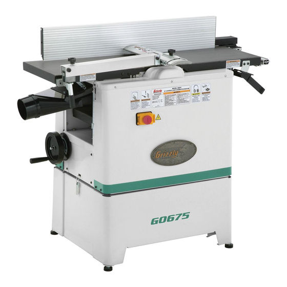
INTRODUCTION Manual Accuracy Functional Overview your machine may not exactly match the manual www.grizzly.com Contact Info... - Page 5 Identification Figure 1.
-
Page 6: Machine Data Sheet
Machine Data Sheet JOINTER/PLANER COMBINATION MACHINE Product Dimensions: Shipping Dimensions: Electrical: Motors: Main Main Specifications: Fence Information Cutting Capacities (Jointer) Cutting Capacities (Planer) MACHINE DATA SHEET MODEL G0675... - Page 7 Knife Information (Jointer) Cutterhead Information Table Information (Jointer) Table Information (Planer) Construction Other Infomation Other Specifications: Features:...
-
Page 8: Section 1: Safety
Safety Instructions for Machinery... -
Page 10: Additional Safety Instructions For Jointers
Additional Safety Instructions for Jointers JOINTER KICKBACK. DO NOT CUTTERHEAD ALIGNMENT. PUSH BLOCKS. WORKPIECE SUPPORT. KICKBACK ZONE. MAXIMUM CUTTING DEPTH. Like all machines there is danger associated with this machine. Accidents are frequently caused by lack of familiarity or failure to pay attention. -
Page 11: Additional Safety Instructions For Planers
Additional Safety Instructions for Planers KICKBACK. REACHING INSIDE PLANER. INFEED CLEARANCE SAFETY. BODY POSITION WHILE OPERATING. PLANING CORRECT MATERIAL. GRAIN DIRECTION. LOOKING INSIDE PLANER. CUTTING LIMITATIONS. DO NOT CLEAN STOCK. 10. REMOVING JAMMED WORKPIECES. 11. DULL/DAMAGED KNIVES. 12. UNPLUGGING DURING ADJUSTMENTS. -
Page 12: Section 2: Circuit Requirements
SECTION 2: CIRCUIT REQUIREMENTS 220V Operation Serious personal injury could occur if you connect the machine to power before com- pleting the setup process. DO NOT connect the machine to the power until instructed later in this manual. Electrocution or fire could result if machine is not grounded and installed in compliance with electrical... -
Page 13: Section 3: Setup
SECTION 3: SETUP This machine presents serious injury hazards to untrained users. Read through this entire manu- al to become familiar with the controls and opera- tions before starting the machine! Wear safety glasses dur- ing the entire setup pro- cess! This machine and its com- ponents are very heavy. - Page 14 Inventory Note: If you can't find an item on this list, check the mounting location on the machine or examine the packaging materials carefully. Occasionally we pre-install certain components for shipping purposes. Box 1: (Figure 3) Figure 3. SUFFOCATION HAZARD! Immediately discard all plas- tic bags and packing materi- als to eliminate choking/suf-...
-
Page 15: Site Considerations
Moving & Placing Base Unit The Model G0675 is a heavy machine. Serious personal injury may occur if safe moving methods are not used. To be safe, get assistance and use... -
Page 16: Mounting To Shop Floor
Mounting to Shop Floor To mount the base to the floor: Figure 7 Figure 7. Figure 8. Bolting to Concrete Floors NOTICE Anchor studs are stronger and more per- manent alternatives to lag shield anchors; however, they will stick out of the floor, which may cause a tripping hazard if you decide to move your machine. - Page 17 Assembly Test Run Page 18 Page 22 To assemble the machine: Figure 10 Figure 10. Figure 11 Figure 11. Tip: Try tightening one cap screw several turns, then repeat with other until both are tight. Figure 12 Figure 12. Figure 13 Figure 13.
-
Page 18: Dust Collection
Dust Collection DO NOT operate the Model G0675 with- out an adequate dust collection system. This machine creates substantial amounts of wood dust while operating. Failure to use a dust collection system can result in long- term respiratory illness. Recommended CFM at Dust Port: 400 CFM Do not confuse this CFM recommendation with the rating of the dust collector. - Page 19 Setting Outfeed Table Height To set the outfeed table height: Replacing Flat Drive Belt, Steps 3-4 Page 33 Figure 16 Figure 16. Figure 17 Figure 17. Figure 18. Checking Outfeed Table Parallelism Page 39 Figure 18 . Figure...
- Page 20 Test Run Troubleshooting Page 37 To test run the machine: Page 22, Figure 19. Jointer Operation Setup Step 10 Planer Operation Setup, Steps 1-5 Figure 19 Page 23...
-
Page 21: Recommended Adjustments
Recommended Adjustments SECTION 7: SERVICE ADJUSTMENTS. Factory adjustments that should be verified: Page 42 Page 44 Page 39 Note: Pulleys and belts can get hot. This is a nor- mal condition. Allow them to cool before making adjustments. Page 46 Belt Break-In Page 32... -
Page 22: Basic Jointer Controls
OMMEND that you read books, trade maga- zines, or get formal training before begin- ning any projects. Regardless of the con- tent in this section, Grizzly Industrial will not be held liable for accidents caused by lack of training. Basic Jointer... - Page 23 Fence Movement: Figure 21 Fence Tilting: Figure 22 Page 44 Figure 22. Figure 23 . Figure 23. Blade Guard: Figure 24 Figure 24. Blade Guard Arm: Figure 24...
-
Page 24: Basic Planer Controls
Table Height Handwheel: Figure 25 Table Height Scale: Figure 25. Jointer-Planer Conversion Planer Operation Setup Figure 24 Figure 26. Serious personal injury could occur if you place your fingers between the table and base or between pivot points. Your hands... - Page 25 Figure 27. The dust chute must be secured during planer operations or the machine will not operate. If the machine DOES operate when the dust chute lock is disengaged, immedi- ately DISCONNECT THE JOINTER/PLANER FROM POWER and call Technical Support.
-
Page 26: Stock Inspection And Requirements
Stock Inspection and Requirements Here are some rules to follow when choos- ing stock for the jointer/planer: DO NOT joint or surface plane stock that contains knots. DO NOT joint or surface plane against the grain direction. Jointing and surface planing with the grain produces a better finish and is safer for the operator. -
Page 27: Squaring Stock
Thickness Planer Specific Rules: Figure 31. Squaring Stock Squaring stock involves four steps performed in the order below: Surface Plane on the Jointer Surface Plane on the Thickness Planer Edge Joint on the Jointer Rip Cut on a Table Saw... -
Page 28: Surface Planing
Surface Planing Figures 32 –34 NOTICE If you are not experienced with a jointer, set the depth of cut to 0", and practice feeding the workpiece across the tables as described. This procedure will better pre- pare you for the actual operation. Figure 32. - Page 29 Failure to use push blocks when surface planing may result in cutterhead contact, which will cause serious personal injury. Always use push blocks to protect your hands when surface planing on the jointer. Note: If your leading hand (with push block) gets within 4"...
-
Page 30: Edge Jointing
Edge Jointing Figures 35 & 36 NOTICE If you are not experienced with a jointer, set the depth of cut to 0", and practice feeding the workpiece across the tables as described below. This procedure will better prepare you for the actual operation. Figure 35. -
Page 31: Bevel Cutting
Bevel Cutting 37 & 38 NOTICE If you are not experienced with a jointer, set the depth of cut to 0", and practice feeding the workpiece across the tables as described below. This procedure will better prepare you for the actual operation. Figure 37. -
Page 32: Operation
Thickness Planer Operation To use the planer: Figure 39 Figure 39. Note: Any time you switch directions with the table height handwheel, there will be a small amount of backlash—so the first crank of the handwheel after switching directions will be... -
Page 33: Section 5: Accessories
® H3788—G96 Gun Treatment 12 oz Spray ® H3789—G96 Gun Treatment 4.5 oz Spray Figure 40. G1738—Rotacator™ Precision Planer Tool Figure 41. G9643—8" Precision Straightedge G9644—12" Precision Straightedge H2675—16" Precision Straightedge Figure 42. T20501—Face Shield Crown Protector 4" T20502—Face Shield Crown Protector 7"... -
Page 34: Section 6: Maintenance
Page 36 Annually Page 36 Note: This maintenance schedule is based on average usage. Adjust the maintenance schedule to match your usage to keep your jointer/planer running smoothly and to protect your investment. Page 31 Page 35 Page 35 on this page... -
Page 35: Step
Figure 44. Step 3 Figures 45 Figure 45. Figure 46. Figure 44 Adjusting /Replacing Feed Cylinder Belts Figure 47 Feed Cylinder Belts Adjusting/Replacing Feed Belts Figure 47 Adjusting/Replacing... -
Page 36: Figure
Figure 48 Figure 48. Step 3 Steps 3–5 Lubrication on this page Page 35 Figure 48 Fence Figure 49 Figure 49. Page 35 Page 35 Page 36 Page 36 Page 36... -
Page 37: Figure
Blade Guard Arm Figure 50. Leadscrews 51–52 Photo Note: Show both sides like figure below. Figure 51. Figure Figure 52. Feed Roller Chain, Sprocket and Cogwheels Figures Figure 53. Figure 53... -
Page 38: Figure
Outfeed Table Figure 54 Figure 56 Figure 54. Figure 56. Table Height Chain & Planer Handwheel Figure 55 Figure 55. -
Page 39: Section 7: Service
SECTION 7: SERVICE Troubleshooting... - Page 40 Page 47 Page 43 Page 43 Page 43 Page 43 Page 43...
-
Page 41: Figure
Jointer Table Parallelism Figure 57. Note: Typically, a tolerance of ± 0.005" in parallel- ism between the tables is considered acceptable. Tools Needed Figure 57 Checking Outfeed Table Parallelism To check outfeed table parallelism: Figure 58. Figure 59 Note: Rotate the cutterhead to make sure the knives do not interfere with proper measure- ment. -
Page 42: Figure
Note: The back side of the outfeed table is factory set approximately 0.060" from the cutterhead. The back side of the outfeed table is not adjustable, so any adjustments to parallelism must be made on the front of the outfeed table. Figure 59. -
Page 43: Figure
Checking Infeed Table Parallelism Figure 61. Figure 62 Figure 62. Knives Figure 61 Adjusting Infeed Table Parallelism Knives Inspecting Page 42 Adjusting Infeed Table Parallelism Page 39 Figure 61 Figure 62 Step 4 Inspecting Page 42... -
Page 44: Figure
Figures 63 Figure 63. Figure 64. Figure 62 Tip: Tighten the front and rear bolts finger tight and tap the table up or down. This will help dial in the adjustment. Knives Inspecting Knives Tools Needed: To inspect the knives with the knife setting gauge: Steps 2–7 Height... - Page 45 Adjusting/Replacing Knives Tools Needed: Knife Setting Gauge Method: Figure 65 Figure 65. Figure 66. To set or replace the knives: Figure 66 Page...
-
Page 46: Setting Fence Stops
Figure 65 Figure 67 Steps 5-7 Figure 67. Figure 68. Step 8 Setting Fence Stops Tools Needed Figures 69-70 Figure Figure 69. ˚ Figure 70 ˚... - Page 47 To set the 90˚ fence stop: Figure 69 Figure 70 Figure 71 Figure 71. ˚ To set the 45˚ fence stop: Figure 70 Figure 69 Figure 72 Figure 72.
-
Page 48: Spring Tension
Spring Tension Tools Needed: To adjust feed roller spring tension: Figure 44 Page 33 Figure 73. Figure 74. 1-4, Figure 73 Figure Figure Steps 1-4 Step 8 Steps Step 8 Steps 6-7... - Page 49 Replacing Feed Rollers Tools Needed: To replace the front and rear feed rollers: Figure 44 Page 33 Figure 75. Page 46 Figure 76. Figure 73 Figure 75 Figure 77. Figure 73 Figure 76 Page 46 Figure 77...
-
Page 50: Chain Tension
Step 7 Page 46 Step 6 Chain Tension Tools Needed: To adjust the chain tension: Steps 2–7 Table Parellelism Adjustments During the next step, DO NOT let the chain fall off the sprockets—returning it to its proper location without changing the table adjustments can be very difficult. -
Page 51: Planer Table Parallelism
Planer Table Parallelism Figure 80 Maximum Allowable Tolerances: Tools Needed: SIDE-TO-SIDE Figure 80 FRONT Figure 81 Table Parallelism Inspection FRONT VIEW Figure 83 To inspect the cutterhead-table parallelism: Figure 81 BACK Page 31 Figure 82 Page 50... - Page 52 Figure 82 Figure 82. Figure 83 Figure 83. Table Parallelism Adjustments To adjust the table parallelism: Figure 84. Figure 84...
-
Page 53: Anti-Kickback Fingers
Page 48 Note: If the left side of the table is too high (viewed from the planer table infeed), the front and rear left sprockets will need to be adjusted. Each tooth on the sprocket rep- resents .007" of vertical movement as the cogs are turned. -
Page 54: Section 8: Wiring
SHOCK HAZARD. QUALIFIED ELECTRICIAN. WIRE CONNECTIONS. MODIFICATIONS. CIRCUIT REQUIREMENTS. Page 10 The photos and diagrams included in this section are best viewed in color. You can view these pages in color at www.grizzly.com. MOTOR WIRING. WIRE/COMPONENT DAMAGE. CAPACITORS. EXPERIENCING DIFFICULTIES. -
Page 55: Wiring Overview
Wiring Overview Figure 86 Page 55 WIRING HARNESS KEY Page 55 Page 54 Page 55 220 VAC 6-15 PLUG Recommended Figure 87 READ ELECTRICAL SAFETY ON PAGE 52! - Page 56 ON/OFF Switch Assembly Wiring Figure 88. View this page in color at www.grizzly.com. Figure 88 WARNING! SHOCK HAZARD! Disconnect power before working on wiring. Page 55 Figure 89. READ ELECTRICAL SAFETY ON PAGE 52! WIRING HARNESS KEY Page 55 Page 55...
- Page 57 Components Wiring Figure 90 Figure 90 WIRING HARNESS KEY Figure 91 Ground 6-15 Plug (As Recommended) Figure 91 READ ELECTRICAL SAFETY ON PAGE 52!
-
Page 58: Section 9: Parts
SECTION 9: PARTS REF PART # DESCRIPTION PSB13M CAP SCREW M8-1.25 X 30 P0675002 TABLE SUPPORT BLOCK P0675003 TABLE SUPPORT BRACKET P0675004 BRACKET PIVOT SHAFT P0675005 RETAINING RING P0675006 INFEED TABLE P0675007 INFEED TABLE INDICATOR PW03M FLAT WASHER 6MM PS14M PHLP HD SCR M6-1 X 12 P0675010 SPECIAL BOLT M8-1.25 X 14... -
Page 59: Motor Assembly Breakdown
Motor Assembly Breakdown REF PART # DESCRIPTION P0675101 CUTTERHEAD LIMIT SWITCH P0675102 CABLE SAFETY RING PB02M HEX BOLT M6-1 X 12 PFN02M FLANGE NUT M6-1 PB07M HEX BOLT M8-1.25 X 25 P0675106 SPECIAL WASHER 8MM P0675107 MOTOR WHEEL P0675108 MOTOR 2.4HP 220V SINGLE-PHASE 108-1 P0675108-1 MOTOR FAN COVER 108-2 P0675108-2... - Page 60 Frame Breakdown REF PART # DESCRIPTION P0675201 OUTSIDE BASE PLATE P0675202 REAR BASE PLATE PSBS09M BUTTON HD CAP SCR M6-1 X 12 PSB01M CAP SCREW M6-1 X 16 P0675205 MOTOR CASE PLATE PLN03M LOCK NUT M6-1 P0675207 PIVOT SHAFT PLN03M LOCK NUT M6-1 P0675209 CASE PLATE...
- Page 61 Fence Assembly Breakdown REF PART # DESCRIPTION P0675301 LOCKING INSERT PLATE P0675302 TAP SCREW M4.8 X 12 P0675303 FENCE COVER P0675304 FENCE P0675305 GUARD PLATE P0675306 TILT LEVER PW03M FLAT WASHER 6MM P0675308 END PLUG P0675309 WING SCREW M6-1 PCB22M CARRIAGE BOLT M6-1 X 16 P0675311 RIP FENCE RAIL...
- Page 62 Feed Gear Assembly Breakdown...
- Page 63 Feed Gear Assembly Parts List REF PART # DESCRIPTION P0675401 LOCKING PLATE P0675402 POSITIONING PLATE PFN01M FLANGE NUT M8-1.25 P0675404 LOCKING CONNECTING PLATE P0675405 ROTATING SHAFT PEC015M E-CLIP 8MM PLW06M LOCK WASHER 10MM PLN05M LOCK NUT M10-1.5 PW04M FLAT WASHER 10MM PRP78M ROLL PIN 4 X 10 P0675411...
- Page 64 Cutterhead-Feed Rollers Breakdown REF PART # DESCRIPTION P0675501 CUTTERHEAD WITH KNIVES P0675502 CUTTERHEAD P0675503 KNIFE P0675504 KNIFE GIB P0675505 KNIFE GIB SCREW P0675506 JACK SCREW P0675507 CUTTERHEAD PULLEY P6005 BALL BEARING 6005ZZ P0675509 CUTTERBLOCK BRACKET P0675510 O- RING P0675511 BEARING CLAMP PSB06M CAP SCREW M6-1 X 25 PFN02M...
- Page 65 Access Panels Breakdown REF PART # DESCRIPTION PS40M PHLP HD SCR M5-.8 X 16 P0675602 RIGHT UPPER COVER P0675603 RIGHT ACCESS PANEL PSBS11M BUTTON HD CAP SCR M6-1 X 10 PW03M FLAT WASHER 6MM P0675606 COVER BRACKET REF PART # DESCRIPTION PSB01M CAP SCREW M6-1 X 16...
-
Page 66: Base Breakdown
REF PART # DESCRIPTION P0675701 BASE SIDE PANEL P0675702 SPECIAL SCREW M6-1 P0675703 RUBBER WASHER 6MM P0675705 BASE PANEL PLN02M LOCK NUT M5-.8 P0675707 CLAMPING HOOK PS09M PHLP HD SCR M5-.8 X 10 Base Breakdown REF PART # PLN03M PN02M P0675711 PB83M P0675713... - Page 67 Planer Table Breakdown...
-
Page 68: Planer Table Parts List
MUST maintain the original location and readability of the labels on the machine. If any label is removed or becomes unreadable, REPLACE that label before using the machine again. Contact Grizzly at (800) 523-4777 or www.grizzly.com to order new labels. -
Page 71: Warranty And Returns
WARRANTY AND RETURNS...
Need help?
Do you have a question about the G0675 and is the answer not in the manual?
Questions and answers