Table of Contents
Advertisement
Toledo q35T
S5220
///
Version 1.1
Copyright
Copyright © TYAN Computer Corporation, 2007. All rights reserved. No part of this
manual may be reproduced or translated without prior written consent from TYAN
Computer Corp.
Trademark
All registered and unregistered trademarks and company names contained in this
manual are property of their respective owners including, but not limited to the
following.
TYAN, Toledo q35T are trademarks of TYAN Computer Corporation.
Intel®, Intel® Core 2 Duo / Wolfdale / Yorksfield Quad Core processor, Q35, and
combinations thereof are trademarks of Intel Corporation.
Phoenix, Phoenix-AwardBIOS are trademarks of Phoenix Technologies.
Microsoft, Windows are trademarks of Microsoft Corporation.
SuSE is a trademark of Novell.
IBM, PC, AT, and PS/2 are trademarks of IBM Corporation.
Notice
Information contained in this document is furnished by TYAN Computer Corporation
and has been reviewed for accuracy and reliability prior to printing. TYAN assumes
no liability whatsoever, and disclaims any express or implied warranty, relating to
sale and/or use of TYAN products including liability or warranties relating to fitness
for a particular purpose or merchantability. TYAN retains the right to make changes
to product descriptions and/or specifications at any time, without notice. In no event
will TYAN be held liable for any direct or indirect, incidental or consequential
damage, loss of use, loss of data or other malady resulting from errors or
inaccuracies of information contained in this document.
1
Advertisement
Table of Contents

Related Manuals for TYAN Toledo q35T


Summary of Contents for TYAN Toledo q35T
- Page 1 Toledo q35T S5220 Version 1.1 Copyright Copyright © TYAN Computer Corporation, 2007. All rights reserved. No part of this manual may be reproduced or translated without prior written consent from TYAN Computer Corp. Trademark All registered and unregistered trademarks and company names contained in this manual are property of their respective owners including, but not limited to the following.
-
Page 2: Table Of Contents
Table of Contents Check the box contents! Chapter 1: Introduction Congratulations Hardware Specifications Chapter 2: Board Installation Board Image Block Diagram Board Parts, Jumpers and Connectors Tips on Installing Motherboard in Chassis Installing the Memory Installing the Processor and Cooling Fan Attaching Drive Cables Installing Add-in Cards Installing Optional SO-DIMM Modules... -
Page 3: Check The Box Contents
Check the box contents! 1x S5220 motherboard 1 x Ultra-DMA-133/100/66/33 IDE cable 3 x Serial ATA power cables 3x Serial ATA cables 1x USB2.0 cable 1 x S5220 user’s manual 1 x S5220 Quick Reference guide 1 x TYAN driver CD 1 x I/O shield If any of these items are missing, please contact your vendor/dealer for replacement before continuing with the installation process. - Page 4 NOTE...
-
Page 5: Chapter 1: Introduction
Chapter 1: Introduction 1.1 - Congratulations You have purchased one of the most powerful server solutions available. The ® Toledo q35T (S5220) is a flexible Intel platform for multiple applications, based on ® the Intel Q35 memory Controller Hub (GMCH) and 82801IR I/O Controller Hub (ICH9R) chipsets. -
Page 6: Power Supply
Memory BIOS • Four 240-pin DDR2 sockets support • Phoenix BIOS on 8Mbit LPC Flash up to 8 GB • Dual channel memory bus (must be • Supports boot from USB device populated in pairs) • Supports ACPI 2.0 • Un-buffered, non-ECC DDR2 667/800 •... -
Page 7: Chapter 2: Board Installation
Chapter 2: Board Installation You are now ready to install your motherboard. The mounting hole pattern of the Toledo q35T (S5220) matches the ATX specification. Before continuing with installation, confirm that your chassis supports an ATX motherboard. How to install our products right… the first time The first thing you should do is reading this user’s manual. -
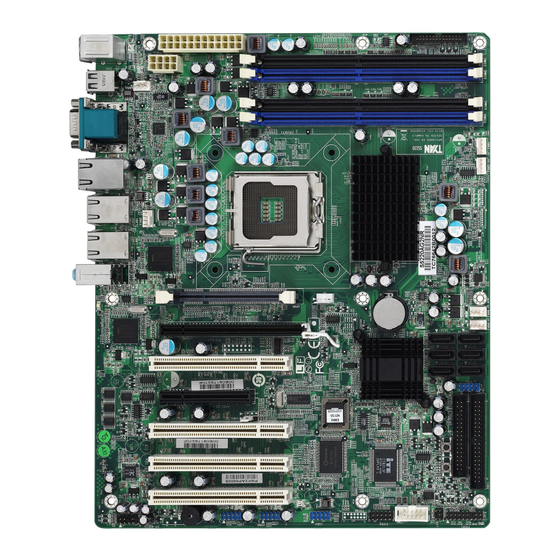
Page 8: Board Image
2.1- Board Image Toledo q35T S5220 This picture is representative of the latest board revision available at the time of publishing. The board you receive may or may not look exactly like the above picture. -
Page 9: Block Diagram
2.2 - Block Diagram Toledo q35T S5220... -
Page 10: Board Parts, Jumpers And Connectors
2.3 - Board Parts, Jumpers and Connectors This diagram is representative of the latest board revision available at the time of publishing. The board you receive may not look exactly like the above diagram. Jumper Legend OPEN - Jumper OFF, without jumper cover CLOSED –... - Page 11 Jumper/Connector Function COM2 COM2 Header CPUFAN1, FAN2/3/4/5/6 4-pin Fan Connector with Tachometer USB3/USB4/USB5/USB6 USB Front Panel Connector TYFP1 Front Panel Connector TYFP2/TYFP3 Front Panel Connector for Barebone LCM Connector for Barebone OPMA Connector (supports TYAN M3295) Aux. Power Connector for TYAN Riser Card (M2061) FP-AUDIO Front Panel Audio Connector...
- Page 12 CPUFAN1 FAN5 FAN2 FAN3 FAN6 FAN4 TYFP1...
- Page 13 CPUFAN1/FAN2~FAN6: 4-pin Fan Connector with Tachometer Use these headers to connect the 4-pin cooling fans to your motherboard to keep the system stable and reliable. +12V CPUFAN1: J7 FAN2: J6 Tachomet er FAN3: J53 FAN4: J47 PWM C ontrol FAN5: J51 FAN6: J48 These connectors support the tachometer monitoring and auto fan speed control.
- Page 14 SATA1 SATA4 SATA2 SATA5 SATA3 SATA6 USB4 FP-AUDIO USB6 COM2 USB5 USB3...
- Page 15 USB3/USB4/USB5/USB6: USB Front Panel Connector Signal Signal +5V Standby +5V Standby USB_A- USB_B- USB_A+ USB_B+ Key Pin USB3: J25 USB5: J21 USB4: J39 USB6: J22 Use these headers to connect to the USB devices via the enclosed USB cable. COM2 (J29): COM2 Header Use these pin definitions to connect a port to COM2.
- Page 16 TYFP3 TYFAN TYFP2...
- Page 17 TYFP2 (J28) : Front Panel Connector for Barebone It is designed for barebone use only Signal Signal LAN1 LED+ LAN1 LED- LAN2 LED+ LAN2 LED- ID LED+ ID LED- ID SW+ ID SW- Key Pin TYFP3 (J31) : Front Panel Connector for Barebone It is designed for barebone use only Signal Signal...
- Page 18 CMOS...
- Page 19 CMOS (J14): Clear CMOS Jumper Use this jumper when you have forgotten your system/setup password or need to clear the system BIOS settings. How to clear the CMOS data: Power off system and disconnect the power supply Normal from the AC source (Default) Use jumper cap to close Pin 2 and 3 for several seconds to Clear CMOS...
-
Page 20: Tips On Installing Motherboard In Chassis
2.4 - Tips on Installing Motherboard in Chassis Before installing your motherboard, make sure your chassis has the necessary motherboard support studs installed. These studs are usually metal and are gold in color. Usually, the chassis manufacturer will pre-install the support studs. If you are unsure of stud placement, simply lay the motherboard inside the chassis and align the screw holes of the motherboard to the studs inside the case. -
Page 21: Installing The Memory
2.5 - Installing the Memory Before installing memory, ensure that the memory you have is compatible with the motherboard and processor. Only DDRII-800/667 DIMM modules are required. Check the TYAN Web site at: www.tyan.com for details of the type of memory recommended for your motherboard. - Page 22 Memory Installation Procedure Follow these instructions to install memory modules into the S5220. Press the locking levers in the direction shown in the following illustration. Align the memory module with the socket. The memory module is keyed to fit only one way in the socket. Key slot Seat the module firmly into the socket by gently pressing down until it sits flush with the socket.
-
Page 23: Installing The Processor And Cooling Fan
2.6 - Installing the Processor and Cooling Fan Your S5220 supports the latest processor technologies from Intel. Check the TYAN website for latest processor support: http://www.tyan.com Processor Installation (LGA 775 Socket) The processor should be installed carefully. Make sure you are wearing an antistatic strap and handle the processor as little as possible. - Page 24 Remove the PnP cap from the load plate. PnP cap Replace the load plate and return the locking lever to the locking position. The CPU installation is now complete. Cooling Fan Installation After you have installed the processor, the heatsink should be installed to ensure that the processor runs efficiently and does not overheat.
- Page 25 Turn the board upside down and insert the heat sink spring mechanism as shown. Align the heatsink with the four holes around the processor socket. Press the heatsink down until the four screws are securely seated in the holes. Use screw drive to secure the four screws.
-
Page 26: Attaching Drive Cables
2.7 - Attaching Drive Cables Attaching IDE Drive Cable Attaching the IDE drive cable is simple. These cables are “keyed” to only allow them to be connected in the correct manner. TYAN motherboards have two on- board IDE channels, each supporting two drives. The black connector designates the Primary channel, while the white connector designates the Secondary channel. -
Page 27: Installing Add-In Cards
The following pictures illustrate how to connect an SATA drive 1. SATA drive cable connection 2. SATA drive power connection 3. SATA cable motherboard connector 4. SATA drive power adapter 2.8 - Installing Add-In Cards Before installing add-in cards, it’s helpful to know if they are fully compatible with your motherboard. -
Page 28: Installing Optional So-Dimm Modules
2.9 - Installing Optional SO-DIMM modules Your S5220 motherboard is equipped with an optional proprietary SO-DIMM connector. The 200-pin vertical SO-DIMM connector can be used for TYAN M3295 expansion card to provide such features as additional TYAN SMDC modules support. For details of available expansions cards, visit the TYAN website at http://www.tyan.com. -
Page 29: Connecting External Devices
2.10 - Connecting External Devices The following diagram will detail the rear port stack for this S5220 motherboard: Line-In Line-Out Mouse Serial Port IPMI LAN Gigabit Keyboard VGA Port USB x 2 Ethernet x 2 USBx2 NOTE: Peripheral devices can be plugged straight into any of these ports but software may be required to complete the installation. -
Page 30: Installing The Power Supply
2.11 - Installing the Power Supply There are two power connectors on your mainboard. The board requires that you use an EPS12V power supply that has a 24-pin and an 8-pin power connector. Please be aware that ATX 2.x, ATX12V and ATXGES power supplies are not compatible with the motherboard and can damage. -
Page 31: Chapter 3: Bios Setup
Chapter 3: BIOS Setup 3.1 About the BIOS The BIOS is the basic input/output system, the firmware on the motherboard that enables your hardware to interface with your software. This chapter describes different settings for the BIOS that can be used to configure your system. The BIOS section of this manual is subject to change without notice and is provided for reference purposes only. - Page 32 Getting Help Pressing [F1] displays a small help window that describes the appropriate keys to use and the possible selections for the highlighted item. To exit the Help Window, press [ESC] or the [F1] key again. In Case of Problems If you discover that you have trouble booting the computer after making and saving the changes with the BIOS setup program, restart the computer by holding the power button down until the computer shuts off (usually within 4 seconds);...
-
Page 33: Main Bios Setup
3.2 Main BIOS Setup When you enter PhoenixBIOS CMOS Setup Utility, the following screen will appear as below: PhoenixBIOS Setup Utility Main Advanced Security Power Boot Exit System Time: Item Specific Help [xx:xx:xx] [xx/xx/xxxx] System Date: [Tab], [Shift-Tab], or [Disabled ] Legacy Diskette A: [Enter] selects field. -
Page 34: Main Menu
3.3 Main In this section, you can alter general features such as the date and time, as well as access to the IDE configuration options. Note that the options listed below are for options that can directly be changed within the Main Setup screen. Users use the arrow keys to highlight the item and then use the <PgUp>... - Page 35 3.3.1 SATA Port 1~6/Ext. Primary Master/Slave Computer detects the hard disk drive type for each drive. Press [Enter] to view advanced details of the corresponding drive. PhoenixBIOS Setup Utility Main Advanced Security Power Boot Exit Item Specific Help Type: [Auto] User = your enter parameters of hard-disk [Disabled]...
- Page 36 32 Bit I/O Enables or disables 32 bit data transfer mode. Enabling this option causes the PCI hard disk interface controller to bundle together two 16-bit chunks of data from the drive into a 32-bit group, which is then transmitted to the processor or memory. This results in a small performance increase.
- Page 37 3.3.2 Memory Cache This setting allows you to tweak the various cache settings for optimal performance of your system. Press [Enter] to display the various cache settings. PhoenixBIOS Setup Utility Main Advanced Security Power Boot Exit Memory Cache Item Specific Help [Write Protect] Cache System BIOS area: Controls caching of...
- Page 38 program writes into this memory area, it will result in a system crash. So, it is recommended that you write protect this area for optimal system performance. Options: uncached / Write Protect Cache Base 0-512K Control caching of 512K base memory. Options: uncached / Write Through / Write Protect / Write Back Cache Base 512-640K Control caching of 512K-640K base memory.
- Page 39 3.3.3 Boot Features This setting allows you to tweak the various boot settings for optimal performance of your system. Press [Enter] to display the various boot features. PhoenixBIOS Setup Utility Main Advanced Security Power Boot Exit Boot Features Item Specific Help Enabled verifies floppy Floppy Check [Disabled]...
- Page 40 QuickBoot Mode Allows the system to skip certain tests while booting. This will decrease the time needed to boot the system. Options: Disabled / Enabled Extended Memory Testing Determines the tests that will be run on extended memory (memory above 1MB) during boot up.
-
Page 41: Advanced Menu
3.4 Advanced This section facilitates configuring advanced BIOS options for your system. PhoenixBIOS Setup Utility Main Advanced Security Power Boot Exit Setup Warning Item Specific Help Setting items on this menu to incorrect values may cause your system to malfunction. Advanced Chipset Control Select options for Advanced Processor Options... - Page 42 3.4.1 Advanced Chipset Control This section allows you to fine tune the chipset configuration. PhoenixBIOS Setup Utility Main Advanced Security Power Boot Exit Advanced Chipset Control Item Specific Help These items determine Integrated Device Control Sub-Menu whether the integrated PCI Express Sub-Menu PCI Devices will be [Disabled] Enabled in PCI Config.
- Page 43 Memory Reclaiming It allows you to enable or disable the system memory remap function. Options: Enabled / Disabled Default Primary Video Adapter Select [IGD] to have Internal Graphics, if supported and enabled, be used for the boot display device. Select [PEG] to have PCI Express Graphics, if supported and enabled, be used for the boot display device.
- Page 44 Native Mode Operation This feature is used to choose Native Mode for ATA. However, certain OS is not supported under Native Mode. Options: Auto / Serial ATA SATA RAID Enable When this option is enabled, the Silicon Image RAID BIOS is loaded on system start up, allowing for configuration of hardware RAID arrays.
- Page 45 3.4.1.1 Integrated Device Control Sub-Menu PhoenixBIOS Setup Utility Main Advanced Security Power Boot Exit Integrated Device Control Sub-Menu Item Specific Help LAN Control Sub-Menu These items control LAN devices USB Dev #29 [Fun #0, 1, 2, 3, 7] USB Dev #26 [Fun #0, 1, 2, 7] Help Select Item...
- Page 46 3.4.1.1.1 LAN Control Sub-Menu PhoenixBIOS Setup Utility Main Advanced Security Power Boot Exit LAN Control Sub-Menu Item Specific Help Enable/Disable for the LAN1 [Enabled] [Disabled] integrated LAN device. LAN1 Option ROM Scan: [Enabled] LAN2 [Disabled] LAN2 Option ROM Scan: Help Select Item Change Values Setup Defaults...
- Page 47 3.4.1.2 PCI Express Sub-Menu PhoenixBIOS Setup Utility Main Advanced Security Power Boot Exit PCI Express Sub-Menu Item Specific Help These items are for PCI Express Base Address debugging the PCI GMCH Base Address Express Graphics Port. DMI Base Address Egress Port Base Address ------------------------------------------------------------------------- PCI-E1 Sub-Menu ICH9 RCB Base Address...
- Page 48 3.4.1.2.1 PCI-E1 Sub-Menu PhoenixBIOS Setup Utility Main Advanced Security Power Boot Exit PEI-E1 Sub-Menu Item Specific Help Disabled --- Port always PCI Express Graphics Port [Auto] disabled. ------------------------------------------------------------------------- Enabled --- Port always PEG Enabled enabled. PEG Number Auto --- Only enable if PEG Width card found.
- Page 49 3.4.1.2.2 PCI-E2 Sub-Menu PhoenixBIOS Setup Utility Main Advanced Security Power Boot Exit PCI-E2 Sub-Menu Item Specific Help Disabled --- Port always PCI-E Port 1 [Auto] disabled. ------------------------------------------------------------------------- (If Port #1 is disabled, Port #1 Enabled then the rest of the Port #1 Number Ports will also be Port #1 Width...
- Page 50 3.4.2 Advanced Processor Options This section allows you to fine-tune the processor options. PhoenixBIOS Setup Utility Main Advanced Security Power Boot Exit Advanced Processor Options Item Specific Help [Enabled] Enabling Hyperthreading: [Enabled] Hyperthreading Core Multi-Processing activates additional [Disabled] Single Logical Proc. Mode CPU threads.
- Page 51 C1 Enhanced Mode This feature is used to enable the C1 Enhanced mode. Options: Enabled / Disabled PECI Interface It is used to enable/disable the Platform Environment Control Interface (PECI). Options: Disabled / Enabled Intel ® Virtualization Technology Intel Virtualization Technology is a set of platform features that support virtualization of platform hardware and multiple software environments.
-
Page 52: Floppy Disk Controller
3.4.3 I/O Device Configuration This setting allows you to configure I/O devices. PhoenixBIOS Setup Utility Main Advanced Security Power Boot Exit I/O Device Configuration Item Specific Help Configure using these Floppy disk controller [Enabled] options: [Enabled] Serial port A: [3F8] [Disabled] No Base I/O address: [IRQ4]... - Page 53 3.4.4 DMI Event Logging This section allows you to fine tune the DMI Event Logging configuration. PhoenixBIOS Setup Utility Main Advanced Security Power Boot Exit DMI Event Logging Item Specific Help Report the validity of Event log validity the DMI event log Event log capacity View DMI event log [Enabled]...
- Page 54 3.4.5 Hardware Monitor This section allows you to fine tune the Hardware Monitor configuration. PhoenixBIOS Setup Utility Main Advanced Security Power Boot Exit Hardware Monitor Item Specific Help Voltage Monitoring CPU FAN1 FAN2 FAN3 FAN4 FAN5 FAN6 CPU Temp. Ambient1 Temp. Ambient2 Temp.
- Page 55 3.4.5.1 Voltage Monitoring Sub-Menu PhoenixBIOS Setup Utility Main Advanced Security Power Boot Exit Voltage Monitoring Item Specific Help CPU Vcore Vddr2 3.3V Help Select Item Change Values Setup Defaults ↑↓ Exit Select Menu Enter Select ← → Sub-Menu Previous Values All items on this submenu can not be modified in user mode.
- Page 56 3.4.6 IPMI This section allows you to configure the IPMI settings. (This submenu will appear when an IPMI card is installed.) PhoenixBIOS Setup Utility Main Advanced Security Power Boot Exit IPMI Item Specific Help Display the System System Event Log Event Log System Event Log (list mode) Realtime Sensor Data...
- Page 57 BIOS POST Watchdog Select [Disabled] if users don’t want to stop POST with any error. Options: Disabled / Enabled OS Boot Watchdog Disable or select Watchdog Timer count mode. Options: Disabled / mSecond / Second / Minute Timer for loading OS (SEC) Watch dog timer value.
- Page 58 3.4.6.2 System Event Log (list mode) Sub-Menu PhoenixBIOS Setup Utility Main Advanced Security Power Boot Exit System Event Log (list mode) Event ID Sensor Name Sensor Type Date/Time Stamp 0007 V5VSB Voltage 03.17.2073 13:10:08 Lower Critical Going Low, Assertion Help Select Item Change Values Setup Defaults...
- Page 59 3.4.6.3 Realtime Sensor Data Sub-Menu PhoenixBIOS Setup Utility Main Advanced Security Power Boot Exit Realtime Sensor Data Sensor Sensor Sensor Sensor Lower Upper Type Name Data Units Limit Limit Temp LocalTemp2 0.00 degrees C 0.00 59.00 H1_THERM 0.00 degrees C 0.00 75.00 LocalTemp1...
-
Page 60: Console Redirection
3.4.7 Console Redirection This section allows you to configure the Console Redirection. PhoenixBIOS Setup Utility Main Advanced Security Power Boot Exit Console Redirection Item Specific Help [Disabled] If enabled, it will use a Com Port Address port on the motherboard. [19.2K] Baud Rate [VT 100]... -
Page 61: Security Menu
3.5 Security These settings allow you to configure the security options for your system. PhoenixBIOS Setup Utility Main Advanced Security Power Boot Exit Item Specific Help Supervisor Password Is: User Password Is: Set Supervisor Password Set User Password [Supervisor] Disk access [Normal] Fixed disk boot sector [Disabled]... -
Page 62: Power Menu
3.6 Power Use this screen to select options for the Power Settings Configuration. PhoenixBIOS Setup Utility Main Advanced Security Power Boot Exit Item Specific Help [S1/S3] ACPI Sleep Mode [Off] Resume on Time Select one of the ACPI Resume Time power states: S1, S2, or [No] Chassis Intrusion detect... -
Page 63: Boot Menu
3.7 Boot Use this screen to select options for the Boot Settings Configuration. PhoenixBIOS Setup Utility Main Advanced Security Power Boot Exit Item Specific Help Boot priority order Excluded from boot order Help Select Item Change Values Setup Defaults ↑↓ Exit Select Menu Enter... -
Page 64: Exit Menu
3.8 Exit These settings set the exit options on your system. PhoenixBIOS Setup Utility Main Advanced Security Power Boot Exit Item Specific Help Exit Saving Changes Exit Discarding Changes Exit system Setup and save your changes to Load Setup Defaults CMOS. -
Page 65: Chapter 4: Diagnostics
Chapter 4: Diagnostics Note: if you experience problems with setting up your system, always check the following things in the following order: Memory, Video, CPU By checking these items, you will most likely find out what the problem might have been when setting up your system. -
Page 66: Phoenix Bios Post Code
4.3 Phoenix BIOS Post Code Code Beeps / Description Code Beeps / Description Verify Real Mode Test CPU bus-clock frequency Disable Non-Maskable Initialize Phoenix Dispatch Interrupt (NMI) Manager Get CPU type Warm start shut down Initialize system hardware Shadow system BIOS ROM Initialize chipset with initial Autosize cache POST values... - Page 67 Code Beeps / Description Code Beeps / Description memory bus Enable cache before Enable external and CPU system BIOS shadow caches 1-4-1-1. RAM failure on Setup System Management data bits of high byte of Mode (SMM) area memory bus Display external L2 cache Check key lock size Load custom defaults...
- Page 68 Code Beeps / Description Code Beeps / Description Install CD ROM for boot Extended checksum (optional) Clear huge ES segment Unknown Interrupt register Fixup Multi Processor table Chipset Init 1-2. Search for option Bridge Init ROMs. Check for SMART Drive Initialize the CPU (optional) Shadow option ROMs...
-
Page 69: Appendix: Smdc Information
Appendix: SMDC Information Overview Tyan Server Management Daughter Card (SMDC) is a powerful yet cost-efficient solution for high-end server management hardware packages. Tyan’s goal is to provide remote system monitoring and control even when the operating system is absence or simply fails. This empowers Tyan’s server board with advanced industrial-standard features. -
Page 70: Features Of Tyan Server Management
Features of Tyan Server Management Monitor various system components remotely - such as fans, processor temperature, and more Remote power on and power off Console redirect -the ability to view system remotely Alert and error actions -such as audible beep, e-mail, power down and reboot SMDC runs on stand-by power -the SMDC will continue to function, even if the system is not powered on... -
Page 71: Glossary
Glossary ACPI (Advanced Configuration and Power Interface): a power management specification that allows the operating system to control the amount of power distributed to the computer’s devices. Devices not in use can be turned off, reducing unnecessary power expenditure. AGP (Accelerated Graphics Port): a PCI-based interface which was designed specifically for demands of 3D graphics applications. - Page 72 Bus: a data pathway. The term is used especially to refer to the connection between the processor and system memory, and between the processor and PCI or ISA local buses. Bus mastering: allows peripheral devices and IDEs to access the system memory without going through the CPU (similar to DMA channels).
- Page 73 IRQs, it is vital that you do not double up devices on a single line. Plug-n-Play devices will take care of this for you. Doze mode: in this mode, only the CPU’s speed is slowed. DRAM (Dynamic RAM): widely available, very affordable form of RAM which has the unfortunate tendency to lose data if it is not recharged regularly (every few milliseconds).
- Page 74 Enhanced IDEs (EIDEs), with maximum capacity determined by the hardware controller. I/O (Input/Output): the connection between your computer and another piece of hardware (mouse, keyboard, etc.) Initial Program Load (IPL): a feature built into BBS-compliant devices, describing those devices as capable of loading and executing an OS, as well as being able to provide control back to the BIOS if the loading attempt fails.
- Page 75 PM timers (Power Management timers): software timers that count down the number of seconds or minutes until the system times out and enters sleep, suspend, or doze mode. PnP (Plug-n-Play): a design standard that has become ascendant in the industry. Plug-n-Play devices require little set-up to use.
- Page 76 design, with cables that are simpler to route and install, smaller cable connectors, and lower voltage requirements. SDRAM (Synchronous Dynamic RAM): called as such because it can keep two sets of memory addresses open simultaneously. By transferring data alternately from one set of addresses and then the other, SDRAM cuts down on the delays associated with non-synchronous RAM, which must close one address bank before opening the next.
-
Page 77: Technical Support
(which can have expensive consequences). If these options are not available for you then Tyan Computer Corporation can help. Besides designing innovative and quality products for over a decade, Tyan has continuously offered customers service beyond their expectations. - Page 78 Returning Merchandise for Service During the warranty period, contact your distributor or system vendor FIRST for any product problems. This warranty only covers normal customer use and does not cover damages incurred during shipping or failure due to the alteration, misuse, abuse, or improper maintenance of products.
- Page 79 Notice for Canada This apparatus complies with the Class B limits for radio interference as specified in the Canadian Department of Communications Radio Interference Regulations. (Cet appareil est conforme aux norms de Classe B d’interference radio tel que specifie par le Ministere Canadien des Communications dans les reglements d’ineteference radio.) Notice for Europe (CE Mark) This product is in conformity with the Council Directive...
Need help?
Do you have a question about the Toledo q35T and is the answer not in the manual?
Questions and answers