Table of Contents
Advertisement
///
Tiger i7505
S2668
Revision 1.00
Copyright © TYAN Computer Corporation, 2002 - 2003. All rights reserved. No part of this manual
may be reproduced or translated without prior written consent from TYAN Computer Corp.
All registered and unregistered trademarks and company names contained in this manual are
property of their respective owners including, but not limited to the following.
TYAN, Tiger i7505 S2668 are trademarks of TYAN Computer Corporation.
Intel, Xeon, and combinations thereof are trademarks of Intel Corporation.
Microsoft and Windows are trademarks of Microsoft Corporation.
Phoenix BIOS is a trademark of Phoenix Technologies.
Winbond is a trademark of Winbond Electronics Corporation.
Promise is a trademark of Promise Technology.
IBM, PC, AT, PS/2 are trademarks of IBM Corporation.
Portable Document Format (PDF) is a trademark of Adobe Corporation.
Information contained in this document is furnished by TYAN Computer Corporation and has been
reviewed for accuracy and reliability prior to printing. TYAN assumes no liability and disclaims any
express or implied warranty relating to sale and/or use of TYAN products; we also assume no
including liability or warranties relating to fitness for a particular purpose or merchantability. TYAN
retains the right to make changes to product descriptions and/or specifications at any time without
notice. In no event will TYAN be held liable for any direct or indirect, incidental or consequential
damage, loss of use, loss of data or other malady resulting from errors or inaccuracies of
information contained in this document.
1
http://www.TYAN.com
Advertisement
Table of Contents

Related Manuals for TYAN TIGER I7505


Summary of Contents for TYAN TIGER I7505
- Page 1 In no event will TYAN be held liable for any direct or indirect, incidental or consequential damage, loss of use, loss of data or other malady resulting from errors or inaccuracies of information contained in this document.
-
Page 2: Table Of Contents
4.4 Using FastBuild Configuration Utility ………………………………..Page 40 Chapter 5: Diagnostics ………………………………..Page 46 5.1 Beep Codes ………………………………..Page 46 5.2 Flash the BIOS ………………………………..Page 46 Appendix I: Glossary ………………………………..Page 47 Appendix II: BIOS POST Code ………………………………..Page 51 Technical Support ………………………………..Page 53 http://www.TYAN.com... -
Page 3: Before You Begin
1x Ultra-DMA-100/66/33 IDE cable (2 for models with Promise SATA RAID) 2x Serial ATA cable (only for models with Promise SATA RAID) 1x Tiger i7505 User’s Manual 1x TYAN driver CD 2x Promise RAID driver diskette (only for models with Promise SATA RAID) -
Page 4: Chapter 1: Introduction
You are now the owner of one of the most advanced dual Intel Xeon processor solutions available: the Tiger i7505. Based on Intel's E7505 chipset, the Tiger i7505 is Hyper-Threading ready - utilizing onboard resources so that many data threads can be handled with ease by two processors. - Page 5 One floppy connector FCC DoC (Declaration of Conformity) Two 9-pin UART Serial connector European CE (Declaration of Conformity) One 25-pin ECP/EPP/SPP parallel connector System Management Total six 3-pin fan headers (three with tachometer monitoring) Temperature, voltage and fan monitoring http://www.TYAN.com...
-
Page 6: Chapter 2: Board Installation
Chapter 2: Board Installation Installation You are now ready to install your motherboard. The mounting hole pattern of the Tiger i7505 matches the ATX board specification. Before continuing with installation, confirm that your chassis supports a standard ATX motherboard form factor. -
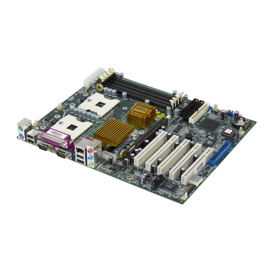
Page 7: Board Image
2.0 – Board Image The following is an image of the Tiger i7505 S2668. This picture is representative of the latest board revision available at the time of publishing. The board you receive may or may not look exactly like the above picture. -
Page 8: Board Parts, Jumpers And Connectors
The board you receive may not look exactly like the above diagram. Jumper Legend Jumper OFF without jumper cap Jumper ON with jumper cap Indicates where the location of pin-1 Indicates where the location of pin-1 http://www.TYAN.com... -
Page 9: Jumper And Connector Settings
Close Pin-2 and 3: Clear CMOS Mode* Fan Connector Chassis Intrusion Connector Front Panel Audio Connector Front Panel USB Connector Front Panel System Connector Fan Connector Fan Connector With tachometer monitoring * Refer to Page 11 for CMOS clearing procedures http://www.TYAN.com... - Page 10 2.5 – Fan Connectors (J20, J21, J23, J37, J43 and J44) (J23,J37,J43 w/o tachometer) Use these headers to connect chassis and processor cooling fans to your motherboard. Cooling fans can keep the system stable and reliable for its product life. Max 850mA fans supported http://www.TYAN.com...
- Page 11 Power off system and disconnect power supply from AC source Use jumper cap to close Pin-2 and 3 for several seconds to Clear CMOS Replace jumper cap to close Pin-1 and 2 (default setting) Reconnect power supply to AC source Power on system http://www.TYAN.com...
- Page 12 MIC power Analog VCC Right line Right line output return Left line Left line output return 2.11 – Front Panel USB Connector (J40) Signal Signal Description Description Channel E Channel F Data- Data- Channel E Channel F Data+ Data+ connected http://www.TYAN.com...
-
Page 13: Oem Reserved Connectors And Jumpers
Switch 2.13 – OEM Reserved Connectors and Jumpers Those connectors and jumpers which are not listed are reserved for OEM or factory use only. 2.14 – POST (Power-On-Self-Test) Code LED Refer to Appendix II for BIOS POST Code list http://www.TYAN.com... -
Page 14: Mounting The Motherboard
Supports 128MB, 256MB, 512MB and 1GB unbuffered DDR200/266 modules • Supports up to 4GB of memory DIMM1 + DIMM2 DIMM3 + DIMM4 DIMM1 + DIMM2 + DIMM3 + DIMM4 DDR Unbuffered Non-ECC √ supported DDR Unbuffered ECC √ supported DDR Registered ECC unsupported http://www.TYAN.com... - Page 15 To avoid bending and damaging your motherboard, place it on its anti-static bag and onto a flat surface, then proceed with memory installation. For important memory information, please check Tyan’s web site at www.tyan.com recommendations.
-
Page 16: Installing The Processor And Heatsink
2.17 – Installing the Processor(s) and Heatsink(s) Your Tiger i7505 S2668 supports the latest processor technologies from Intel. Check the following page on TYAN’s website http://www.tyan.com for latest processor support: The following diagrams will detail how to install your processor(s): Only identical CPUs can be used. - Page 17 Repeat process to mount all other brackets d. Seat heatsink between brackets on the processor e. Attach heatsink clips* The heatsink clips may vary with different mounting brackets http://www.TYAN.com...
-
Page 18: Installing Add-In Cards
Find the appropriate slot for your add-in card and insert the card firmly. Do not force any add-in cards (or anything else) into any slots if they will not seat in place. YOU MUST unplug the power supply before performing system hardware NOTE changes in order to avoid damaging the board or expansion device. http://www.TYAN.com... -
Page 19: Connecting External Devices
LAN Link/Activity LED Scheme Link LED Activity LED (left side) (right side) 10Mbps Blink 100Mbps Orange Blink 1000Mbps Green Blink 4. Microphone Jack 5. Line-In Jack 6. Line-Out Jack 7. USB2.0 Port 8. Serial Port 9. USB2.0 Port 10. PS/2 Keyboard Port http://www.TYAN.com... -
Page 20: Installing The Power Supply
2.20– Installing the Power Supply There are three power connectors on your Tiger i7505 S2668. By default, the Tiger i7505 S2668 requires that you have an EPS12V power supply that has a 24-pin and an 8-pin power connector. However, the Tiger i7505 S2668 is also ATX12V compatible. All 3 power connectors need to be used if you plan on using the ATX12V power. -
Page 21: Attaching Ide And Floppy Drive Cables
Attaching IDE drive cabling is simple. These cables are “keyed” to only allow them to be connected in the correct manner. Tyan motherboards have two on-board IDE channels, each supporting two drives. The black connector designates the Primary channel, while the white connector designates the Secondary channel. -
Page 22: Finishing Up
In the rare circumstance that you have experienced difficulty, you can find help by asking your vendor for assistance. If they are not available for assistance, please find setup information and documentation online at our website or by calling your vendor’s support line. http://www.TYAN.com... -
Page 23: Chapter 3:Bios
Use the left/right ( ) arrow keys to make a selection To display a sub-menu (A pointer “ ” marks all sub menus) Use the arrow keys to move the cursor to the sub menu you want. Then press <Enter>. http://www.TYAN.com... -
Page 24: Bios Menu Bar
Select the previous value/setting of the field <F6> or <+> or <Space> Select the next value/setting of the field <F9> Load the default configuration values of the menu <F10> Save and exit <Enter> Execute command or select submenu <Alt-R> Refresh screen http://www.TYAN.com... -
Page 25: Bios Main Menu
Select Yes when required to restore the manufacturer's defaults 3.3.4 – System Time Feature Option Description HH : MM : SS Set the system time 3.3.5 – System Date Feature Option Description MM : DD : YYYY Set the system date http://www.TYAN.com... -
Page 26: Bios Advanced Menu
360 KB This setting selects the type of the 1.3 MB floppy disk drive installed in system. 720 KB 1.44/1.25 MB 2.88 MB Floppy Disk Controller Enabled This setting determines whether the Disabled floppy disk controller is activated. Auto http://www.TYAN.com... - Page 27 Auto – To let BIOS configure the port automatically during POST Parallel Port Mode Bi-directional Output Only Parallel Port Base I/O Address 378 / 278 / 3BC Parallel Port Interrupt IRQ7 / IRQ5 Parallel Port DMA Channel DMA3 / DMA1 http://www.TYAN.com...
- Page 28 This setting determines whether the Disabled option ROM of the PCI slot is loaded during system BIOS POST. Latency Timer Default This setting controls how long each 0020h PCI device can hold the bus before another PCI device takes over. 00E0h http://www.TYAN.com...
-
Page 29: Bios Security Menu
Set to stay off to leave the computer in the power off state. Set to last state to restore the system to the previous status before power failure or interrupt occurred. Set to power on to leave the computer in the power on state. http://www.TYAN.com... -
Page 30: Bios Boot Menu
If the PCI card is not available, it will initialize the AGP card 3.7.4 – Boot Device Priority Sub-Menu The boot menu will list all bootable devices. Arrange the priorities of all bootable devices by using arrow keys and then pressing <Enter>. http://www.TYAN.com... -
Page 31: Bios Exit Menu
Use this option when system CMOS values have been corrupted or modified incorrectly. 3.8.4 – Discard Changes Use this option to restore all new setup values that you have made but not saved into CMOS. 3.8.5 – Save Changes Use this option to store all new setup values into CMOS. http://www.TYAN.com... -
Page 32: Chapter 4:Sata/Raid Setup
Serial ATA ports on the SATA RAID controller. All of the connectors are keyed so they will only attach one way. Note PDC20378 is a PCI Plug-n-Play (PnP) device. No changes are necessary in the Motherboard CMOS Setup for resources or drive types in most applications. http://www.TYAN.com... -
Page 33: Creating You Disk Array
[ Main Menu ] Auto Setup............[ 1 ] View Drive Assignments........[ 2 ] Define Array............[ 3 ] Delete Array............[ 4 ] Rebuild Array............ [ 5 ] [ Keys Available ] Press 1...5 to Select Option [ESC] Exit http://www.TYAN.com... - Page 34 Optimize Array for: Performance [ Array Setup Configuration ] Mode................Stripe Spare Drive................0 Drive(s) used in Array............2 Array Disk Capacity (size in MB) ........16126 [ Keys Available ] [↑] Up [↓] Down [←, →, Space] Change Option [ESC] Exit [Ctrl-Y] Save http://www.TYAN.com...
- Page 35 Proceed with normal FDISK and format procedures as if you had just installed a new hard drive. Once the arrayed drives have been formatted, proceed to Step 4. Installing Software Driver to install your operating system and/or PDC20378 driver. http://www.TYAN.com...
- Page 36 Once complete, the following screen will appear confirming that your Security array has been created. Press any key to reboot the system Array has been created. <Press Any Key to Reboot> Proceed to Step 4. Installing Software Driver to install your operating system and/or PDC20378 driver. http://www.TYAN.com...
-
Page 37: Installing Software Driver
From Windows 2000/XP, open the Control Panel from “My Computer” followed by the System icon. Choose the “Hardware” tab, then click the “Device Manager” tab. Click the “+” in front of “SCSI & RAID Controllers” hardware type. The “Win2000/XP Promise FastTrak 378 (or SATA150 TX Series) Controller” should appear. http://www.TYAN.com... - Page 38 Click on “Next.” The Add New Hardware wizard will say it has found “Win98-ME Promise FastTrak 378 (or SATA150 TX Series) controller”. Click on “Next,” and then on “Finish.” Choose “Yes” when asked if you want to restart your computer. Remove the diskette from drive A:. http://www.TYAN.com...
- Page 39 10. After a successful installation, the “SCSI Adapter Setup” box will show that the “Win NT Promise FastTrak 378 (or SATA150 TX Series) Controller” has been installed. 11. Power off your system. 12. If you plan to move the boot drive to connect the PDC20378, now attach the hard drives otherwise reboot. http://www.TYAN.com...
-
Page 40: Using Fastbuild Configuration Utility
The user should identify the failed drive through the FastBuild Setup utility, and then replace the problem drive. Offline - A striped array has 1 drive that has failed or been disconnected. When the array condition is “offline,” the user must replace the failed drive(s), then restore data from a backup source. http://www.TYAN.com... - Page 41 Optimize Array for: Performance [Array Setup Options Menu] Mode................Stripe Spare Drive................1 Drive(s) used in Array.............2 Array Disk Capacity (size in MB) ........16126 [ Keys Available ] [↑] Up [↓] Down [←, →, Space] Change Option [ESC] Exit [Ctrl-Y] Save http://www.TYAN.com...
- Page 42 FastBuild (tm) Utility 1.xx (c) 1995-2000 Promise Technology, Inc. [ View Drive Assignments ] Channel:ID Drive Model Capacity(MB) Assignment Mode 1 : Mas QUANTUMCR8.4A 8063 Array 1 2 : Mas QUANTUMCR8.4A 8063 Array 1 [ Keys Available ] [↑] Up [↓] Down [ESC] Exit Mode (D=DMA, U=UDMA) http://www.TYAN.com...
- Page 43 Are you sure you want to delete this array? Press Ctrl-Y to Delete, others to Abort After deleting the array, you should create a new array using Auto Setup or the Define Array menu from the FastBuild Main Menu. http://www.TYAN.com...
- Page 44 —— —— Array 4 —— —— —— —— [ Keys Available ] [↑] Up [↓] Down [ESC] Exit [Enter] Select Highlight the array whose Status is “Critical”. 10. Press [Enter]. The following screen will then appear (see next page). http://www.TYAN.com...
- Page 45 A progress bar will appear as below. Please Wait While Duplicating The Image 10% Complete 13. Once the rebuild process is complete, the user will be asked to reboot the system. http://www.TYAN.com...
-
Page 46: Chapter 5: Diagnostics
(2) Graphics initialization failed Before contacting your vendor or Tyan Technical Support, be sure that you note as much as you can about the beep code length and order that you experience. Also, be ready with information regarding add-in cards, drives and O/S to speed the support process and come to a quicker solution. -
Page 47: Appendix I: Glossary
SRAM instead of slower DRAM. Note that the cache is also much smaller than your regular memory: a typical cache size is 512KB, while you may have as much as 4GB of regular memory. http://www.TYAN.com... - Page 48 EEPROM (Electrically Erasable Programmable ROM): also called Flash BIOS, it is a ROM chip which can, unlike normal ROM, be updated. This allows you to keep up with changes in the BIOS programs without having to buy a new chip. TYAN’s BIOS updates can be found at http://www.tyan.com ESCD (Extended System Configuration Data): a format for storing information about Plug-n- Play devices in the system BIOS.
- Page 49 RAID level 1 also allows for faster access time and fault-tolerance, since either hard drive can be read at the same time. RAID level 0+1 is both striping and mirroring, providing fault-tolerance, striping, and faster access all at the same time. RAIDIOS: RAID I/O Steering (Intel) http://www.TYAN.com...
- Page 50 ZIF Socket (Zero Insertion Force socket): these sockets make it possible to insert CPUs without damaging the sensitive CPU pins. The CPU is lightly placed in an open ZIF socket, and a lever is pulled down. This shifts the processor over and down, guiding it into the board and locking it into place. http://www.TYAN.com...
-
Page 51: Appendix Ii: Bios Post Code
Display possible high address for UMB high byte of memory bus recovery Test CPU bus-clock frequency Display error messages Initialize Phoenix Dispatch Manager Check for configuration errors Warm start shut down Check for keyboard errors Shadow system BIOS ROM Set up hardware interrupt vectors http://www.TYAN.com... - Page 52 Initialize System Management Mode POST done - prepare to boot Output one beep before boot operating system One short beep before boot Boot to Mini DOS Terminate QuietBoot (optional) Clear Huge Segment Check password (optional) Boot to Full DOS Prepare Boot http://www.TYAN.com...
-
Page 53: Technical Support
Return Merchandise Authorization (RMA) number. The RMA number should be prominently displayed on the outside of the shipping carton and the package should be mailed prepaid. TYAN will pay to have the board shipped back to you. http://www.TYAN.com... - Page 54 Danger of explosion if battery is incorrectly replaced. Replace only with the same or equivalent type recommended by manufacturer. Dispose of used battery according to manufacturer instructions and in accordance with your local regulations. Document #: D1510 - 100 http://www.tyan.com...
Need help?
Do you have a question about the TIGER I7505 and is the answer not in the manual?
Questions and answers