Table of Contents
Advertisement
Quick Links
Advertisement
Table of Contents

Subscribe to Our Youtube Channel
Related Manuals for Speco HT5100BPVFG


Summary of Contents for Speco HT5100BPVFG
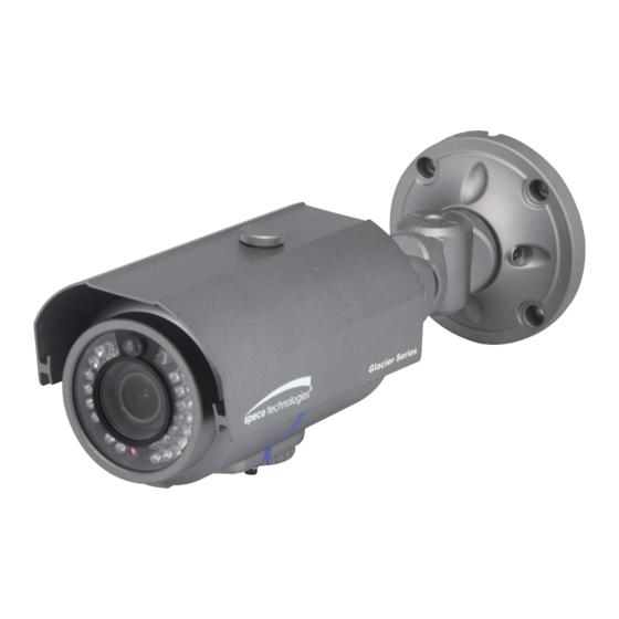
- Page 1 INSTRUCTION MANUAL PIR Sensor Camera HT5100BPVFG / HT5100BPVFGW HT5200BPVFG / HT5200BPVFGW Speco Technologies is constantly developing product improvements. We reserve the right to modify product design and specifications without notice and without incurring any obligation. Rev. 6/20/2012...
-
Page 2: Table Of Contents
Contents Contents ............1 ◑ Precautions ..........2, 3 ◑ Safety Instructions ........4 ◑ Package Contents ........5 ◑ Camera Installation ........6-8 ◑ Specifications ..........9,10 ◑ Camera Dimension ........11 ◑ Features ............12 ◑ OSD Menu Details ........13-26 ◑... -
Page 3: Precautions
Precautions Do not install the camera in Do not install the camera under Do not touch the front lens of the extreme temperature conditions. unstable lighting conditions. camera. Only use the camera under conditions Severe lighting change or flicker can This is one of the most important parts of the where temperatures are between cause the camera to work improperly. - Page 4 CAUTION RISK OF ELECTRIC SHOCK CAUTION DO NOT OPEN CAUTION RISK OF ELECTRIC SHOCK CAUTION:TO REDUCE THE RISK OF ELECTRIC SHOCK RISK OF ELECTRIC SHOCK DO NOT OPEN DO NOT OPEN DO NOT REMOVE COVER(OR BACK). CAUTION:TO REDUCE THE RISK OF ELECTRIC SHOCK NO USER-SERVICEABLE PARTS INSIDE.
-
Page 5: Safety Instructions
Safety Instructions Precautions for use ◑ This camera should be installed by qualified personnel only ◑ There are no user serviceable parts inside ◑ Do not disassemble this camera other than to make initial adjustments ◑ Use a UL approved regulated 24 volt AC or 12 volt DC power supply ◑... -
Page 6: Package Contents
Package Contents Please make sure that the following items are included in the Package: 1) HT5100BPVFG, HT5100BPVFGW, HT5200BPVFG, HT5200BPVFGW • 1 Video Test Connector, Power Jack • 1 Bracket Base • 2 Wrenches • Set Screw - 4 Tapping Screws 4x25 - 4 Hexagon Socket Screws M5x10... -
Page 7: Camera Installation
CAMERA INSTALLATION... -
Page 8: Camera Installation
CAMERA INSTALLATION Compatibility HT5100BPVFG, HT5100BPVFGW, HT5200BPVFG, HT5200BPVFGW CVCJBB INTJBS INTCM... - Page 9 CAMERA INSTALLATION 1. HT5100BPVFG, HT5100BPVFGW, HT5200BPVFG, HT5200BPVFGW CAMERA ASSEMBLY BASE ADAPTOR BRACKET TAPPING SCREW 4X25, 4EA HEXAGON SOCKET SCREW M5X10, 4EA...
-
Page 10: Specifications
PIR Sensor Weatherproof Bullet Camera DC Auto Iris Varifocal Lens(2.8mm-12mm) ■ HT5100BPVFG ■ HT5100BPVFGW 600TV Lines DC Auto Iris Varifocal Lens(2.8mm-12mm) True Day / Night Capability 850nm IR LEDs * 24pcs White LEDs * 6pcs Automatic Thermostatic Sensor Alarm Output SPECIFICATIONS HT5100BPVFG / HT5100BPVFGW MODEL... -
Page 11: Specifications
PIR Sensor Weatherproof Bullet Camera DC Auto Iris Varifocal Lens (5mm-50mm) ■ HT5200BPVFG ■ HT5200BPVFGW 600TV Lines DC Auto Iris Varifocal Lens(5mm-50mm) True Day / Night Capability 850nm IR LEDs * 24pcs White LEDs * 6pcs Automatic Thermostatic Sensor Alarm Output SPECIFICATIONS HT5200BPVFG / HT5200BPVFGW MODEL... -
Page 12: Camera Dimension
CAMERA DIMENSION HT5100BPVFG, HT5100BPVFGW, HT5200BPVFG, HT5200BPVFGW 3.70” 9.70” 6.30”... -
Page 13: Features
General Features Ultra High Sensitivity ◑ - The built-in high sensitivity COLOR CCD produces a clear image even in 0Lux(B/W, IR-LED ON)or lower illumination. 600TV Lines ◑ - By adopting a diagonal 6mm(1/3") 410,000 (NTSC) pixel, 470,000(PAL) pixel SONY CCD, the camera produces clear picture quality with a horizontal resolution of 600 TV lines for color and a horizontal resolution of 700TV lines for BW mode. -
Page 14: Osd Menu Details
OSD Control Button 1. Type A, Type B, Type C of OSD button could be used when it needs to OSD control. 2. Type D is extra Option (wired Remote controller) ▲ Up button: Moves the cursor upwards. Use this button to select an item or adjust the parameters. -
Page 15: Menu Setup
Menu Setup ● 1. Press the Function Setup switch. - Main setup menu is displayed on the monitor screen. MAIN SETUP 1.LENS 2.EXPOSURE 3.WHITE BAL 4.SSDR 5.BACKLIGHT 6.DNR3 7.DAY/NIGHT AUTO 8.SPECIAL 9.EXIT SAVE 2. Select a desired function using the Function Setup switch. - Place the cursor over a desired item. -
Page 16: Exposure Setting
- FOCUS ADJ : To adjust the DC lens focus correctly, you must activate the Focus Settings mode under each lens menu. Activate the Focus Settings mode, adjust the lens focus, and then deactivate the settings mode. ☞ NOTE ■ If color rolling occurs when using a DC lens, set Shutter to Fixed (---). Exposure Setting ●... - Page 17 ◆ AGC(AUTO GAIN CONTROL) : The higher the gain level, the brighter the screen - but the higher the noise. * OFF : Deactivates the AGC function. * LOW : Allows automatic gain control from 5.3dB to 32dB. * HIGH : Allows automatic gain control from 5.3dB to 37dB. ◆...
-
Page 18: Ssdr Setting
※ Select one of the following 5 modes, as appropriate for your purpose. ◆ ATW : Select this when the color temperature is between 1,700˚K and 11,000˚K. ◆ OUTDOOR : Select this when the color temperature is between 1,700˚K and 11,000˚K. (sodium light inclusion) ◆... -
Page 19: Backlight Setting
Backlight Setting ● Unlike conventional cameras, the HT5100BPVFG and HT5200BPVFG are designed to deliver a distinctive subject and background at the same time, even when the subject is backlight, by using the features of the proprietary W-V DSP chip. 1. When the SETUP menu screen is displayed, select 'BACKLIGHT' by using the Function Setup switch so that the arrow indicates 'BACKLIGHT'. -
Page 20: Dnr3 Setting
BLC SETUP HLC SETUP LEVEL LEVEL MIDDLE LIMITS NIGHT ONLY BOTTOM MASK COLOR BLACK LEFT MASK TONE RIGHT BOTTOM Press Set to Return LEFT RIGHT Press Set to Return ☞ NOTE ■ Because there can be a difference in the effectiveness of HLC according to the amount of light area in the screen, optimize the installation angle for the best HLC performance. - Page 21 3. Set the DNR3 mode to 'ON' and press the Function Setup switch. Then you can adjust the noise reduction level. ☞ NOTE ■ You cannot set the DNR3 to ‘ON’ or ‘OFF’ when the AGC mode of the EXPOSURE menu is ‘OFF’. ■...
-
Page 22: Special Setting
◆ AUTO : The mode is switched to 'Color' in a normal environment, but switches to 'B/W' mode when ambient illumination is low. To set up the switching time for AUTO mode, press the Function Setup switch. You can turn on or off the burst signal on B/W mode. - Page 23 2. Select a desired mode using the Function Setup switch. SPECIAL 1.IMAGE ADJ 2.CAM TITLE 3.SYNC 4.MOTION DET 5.PRIVACY 6.DIS 7.COMM ADJ 8.LANGUAGE ENGLISH 9.RETURN ◆ IMAGE ADJ. : 1) When the SETUP menu screen is displayed, select 'IMAGE ADJ' by using the Function Setup switch so that the arrow indicates 'IMAGE ADJ'.
- Page 24 ☞ NOTE ■ When the V-REV or H-REV mode is enabled, the text on the screen does not flip. ■ If you increase the SHARPNESS level too high, the picture may become distorted or noise may appear. ◆ CAM TITLE : If you enter a title, the title will appear on the monitor. 1) If the SPECIAL menu screen is displayed, use the Function Setup switch so that the arrow indicates 'CAM TITLE'.
- Page 25 ☞ NOTE ■ When using AC power at 60Hz(NTSC), 50Hz(PAL), frequency, you can use the L/L type synchronization. ■ When the power is DC 12V, the SYNC menu is fixed to the ‘INT’ mode. ◆ MOTION DET :This product has a feature MOTION DET that allows you to observe movement of 1.SENSITIVITY...
- Page 26 1) When the SPECIAL menu screen is displayed, press the Function Setup switch so that the arrow indicates 'PRIVACY'. 2) Set up the mode using the Function Setup switch. - AREA : You can select up to 12 PRIVACY areas. - MODE : Determines whether to use the area selected in the AREA.
-
Page 27: Exit Setting
Automatic Thermostatic Sensor! 1. Power off under -40 degree, the camera becomes frozen 2. On power on, the first temperature sensor starts working and makes heater work. 3. When the internal temperature in camera goes up to -10 degree, the second temperature sensor starts working and Camera on. In this status the first and second temperature sensor work together. -
Page 28: Trouble Shooting
Trouble Shooting ● PROBLEM POSSIBLE CAUSE ☞Check the power cable, power supply output and video Northing appears on connection between the camera and monitor. the screen. ☞Are the camera lens or the lens glass dirty? Clean the lens / glass with a soft clean cloth. The image on the ☞Adjust the monitor controls, as required. - Page 30 ▶ MEMO...
- Page 31 ▶ MEMO...
- Page 32 200 New Highway Amityville, NY 11701 631-957-8700 1 800 645 5516 www.specotech.com...
Need help?
Do you have a question about the HT5100BPVFG and is the answer not in the manual?
Questions and answers