
Related Manuals for Speco HTINT70T


Summary of Contents for Speco HTINT70T
- Page 1 INSTRUCTION MANUAL HD-TVI Camera HTINT70T, HTINT701T (Bullet Camera) HTINT601T (Turret Camera) HTINT591T (Dome Camera) HT7246T / HT7250T (Dome Camera)
-
Page 2: Table Of Contents
Contents Contents ............1 Precautions ..........2, 3 Safety Instructions ........4 Package Contents ........5 Camera Installation ........6-12 Lens Adjustment ......... 13 ..........13-17 Camera Dimension ........18-19 Features ............20 OSD Menu Details ........21- 36 Trouble Shooting ......... 37... -
Page 3: Precautions
Precautions Do not install the camera in Do not install the camera under Do not touch the front lens of the extreme temperature conditions. unstable lighting conditions. camera. Only use the camera under conditions Severe lighting change or flicker can This is one of the most important parts of where temperatures are between cause the camera to work improperly. - Page 4 RISK OF ELECTRIC SHOCK DO NOT OPEN CAUTION:TO REDUCE THE RISK OF ELECTRIC SHOCK DO NOT REMOVE COVER(OR BACK). NO USER-SERVICEABLE PARTS INSIDE. REFER SERVICING TO QUALIFIED SERVICE PERSONNEL. ISO14001 The lightning flash with an arrowhead symbol, within an equilateral triangle is intended to alert the user to the presence of uninsulated dangerous voltage within the product's enclosure that may be of sufficient magnitude to constitute a risk of electric shock to persons.
-
Page 5: Safety Instructions
Safety Instructions There are no user serviceable parts inside Do not disassemble this camera other than to make initial adjustments Use a UL approved regulated 24 volt AC or 12 volt DC power supply Please insure that your installation area can support the weight of the camera Do not use a strong or abrasive detergent when cleaning the camera Do not install near cooling or heating device... -
Page 6: Package Contents
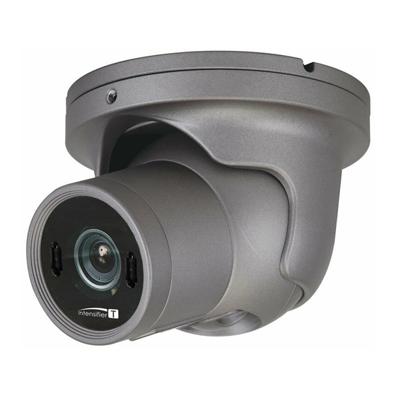
Package Contents Please make sure that the following items are included in the Package: 1) HTINT70T, HTINT701T 2) HTINT601T 3) HTINT591T 4) HT7246T, HT7250T... -
Page 7: Camera Installation
CAMERA INSTALLATION... -
Page 8: Camera Installation
CAMERA INSTALLATION Compatibility 1) HTINT70T, HTINT701T CVCJBB INTJBS INTCM 2) HTINT601T CVCJBD Adaptor plate(60PLATE) with rubber... - Page 9 CAMERA INSTALLATION Compatibility 3) HTINT591T CVCJBD Adaptor plate(59PLATE) with rubber 4) HT7246T, HT7250T INTWM INTPM CVCJBD...
- Page 10 The installation instructions in this manual than that contained in the operating instructions unless you are qualified to do so. CAMERA INSTALLATION 1. HTINT70T, HTINT701T WALL SCREW TS T1, 4X25, TH, SUS, 4EA 3AXIS BRACKET SCREW M5X10, HEXAGON SOCKET, SUS, BK, 4EA...
- Page 11 CAMERA INSTALLATION 2. HTINT601T BALL DOME BASE SCREW TS T1, 4X25, TH, SUS, 3EA BALL DOME BALL DOME BODY...
- Page 12 CAMERA INSTALLATION 3. HTINT591T VANDAL DOME BASE SCREW TS T1, 3.5X20, PH, SUS, 3EA VANDAL DOME BODY BODY OUTER COVER SPECO...
- Page 13 CAMERA INSTALLATION 4. HT7246T, HT7250T PLASTIC ANCHOR 6x30, 3EA VANDAL DOME BASE ASSEMBLY TAPPING SCREW 4X40, 3EA VANDAL DOME BODY ASSEMBLY BODY OUTER COVER...
-
Page 14: Lens Adjustment
LENS ADJUSTMENT 1. HTINT70T Open the cap Focus adjustment Lock screw Zoom adjustment... -
Page 15: Specifications
Intensifier T Series SPECIFICATIONS HTINT70T / HTINT701T Image Sensor 1/3" SONY 2Mega Exmor CMOS Sensor Imx222 1984(H) X 1105(V), 2.19M Pixels Effective Pixels Total pixels 2000(H) X 1121(V), 2.24M Pixels Scanning System Progressive Scan More than 50dB S/N Ratio Digital : 1920X1080(1080p@30f / 1080p@25f))"... - Page 16 Intensifier T Series SPECIFICATIONS HTINT601T Image Sensor 1/3" SONY 2Mega Exmor CMOS Sensor Imx222 Effective Pixels 1984(H) X 1105(V), 2.19M Pixels Total pixels 2000(H) X 1121(V), 2.24M Pixels Scanning System Progressive Scan More than 50dB S/N Ratio Digital : 1920X1080(1080p@30f / 1080p@25f))" Resolution 1280X720(720p@60f / 720p@50f) 1.0Vp-p Composite.
- Page 17 Intensifier T Series SPECIFICATIONS HTINT591T Image Sensor 1/3" SONY 2Mega Exmor CMOS Sensor Imx222 Effective Pixels 1984(H) X 1105(V), 2.19M Pixels Total pixels 2000(H) X 1121(V), 2.24M Pixels Scanning System Progressive Scan More than 50dB S/N Ratio Digital : 1920X1080(1080p@30f / 1080p@25f))" Resolution 1280X720(720p@60f / 720p@50f) 1.0Vp-p Composite.
- Page 18 Intensifier T Series SPECIFICATIONS HT7246T / HT7250T Image Sensor 1/3" SONY 2Mega Exmor CMOS Sensor Imx222 1984(H) X 1105(V), 2.19M Pixels Effective Pixels Total pixels 2000(H) X 1121(V), 2.24M Pixels Scanning System Progressive Scan More than 50dB S/N Ratio Digital : 1920X1080(1080p@30f / 1080p@25f))" Resolution 1280X720(720p@60f / 720p@50f) 1.0Vp-p Composite.
-
Page 19: Camera Dimension
CAMERA DIMENSION 1) HTINT70T, HTINT701T 8.27” 3.94” dia 4.80” 3.38” 2.95” 2) HTINT601T 4.65” dia... - Page 20 CAMERA DIMENSION 3) HTINT591T 3.23” dia 4) HT7246T, HT7250T 5.10” dia 5.10” dia 3.93” dia...
-
Page 21: Features
3D-DNR are appearing on the scene. clear images. Defog Defog or snow. - Page 24 SPECO TECH 1. PRESET INDOOR 2.MAIN SETUP 3.EXIT MENU 1.LENS DCAUTO 2.EXPOSURE 3.WHITE BAL AUTO 4.BACKLIGHT 5.SPECO DNR MIDDLE 6.DAY&NIGHT AUTO 7.IMAGE 8.MOTION 9.SYSTEM RETURN...
- Page 25 NOTE MENU 1.LENS DCAUTO 2.EXPOSURE 3.WHITE BAL AUTO 4.BACKLIGHT 5.SPECO DNR MIDDLE 6.DAY&NIGHT AUTO 7.IMAGE 8.MOTION 9.SYSTEM RETURN...
- Page 26 NOTE MODE MODE INDOOR RETURN MENU 1.LENS 2.EXPOSURE 3.WHITE BAL AUTO 4.BACKLIGHT 5.SPECO DNR MIDDLE 6.DAY&NIGHT AUTO 7.IMAGE 8.MOTION 9.SYSTEM RETURN 2.EXPOSURE BRIGHTNESS |IIIIIIIII|IIIIIIII| 10 SHUTTER AUTO INTENSIFY |IIIIIIIIIIIIIIIIII| 20 RETURN...
- Page 27 NOTE condition. MENU 1.LENS 2.EXPOSURE 3.WHITE BAL AUTO 4.BACKLIGHT 5.SPECO DNR MIDDEL 6.DAY&NIGHT AUTO 7.IMAGE 8.MOTION 9.SYSTEM RETURN...
- Page 28 should be needed. MANUAL KELVIN MIDDLE R-GAIN |IIIIIIIII|IIIIIIIII| 10 B-GAIN |IIIIIIIII|IIIIIIIII| 10 RETURN NOTE change,...
- Page 29 MENU 1.LENS 2.EXPOSURE 3.WHITE BAL AUTO 4.BACKLIGHT 5.SPECO DNR MIDDLE 6.DAY&NIGHT AUTO 7.IMAGE 8.MOTION 9.SYSTEM RETURN where you can make finer adjustments. LEVEL |IIIIIII|IIIIIII| 10 MODE ALL DAY RETURN...
- Page 30 a submenu appears where you can make finer adjustments. H-POS V-POS H-SIZE V-SIZE RETURN WEIGHT MIDDLE RETURN...
- Page 31 MENU 1.LENS 2.EXPOSURE 3.WHITE BAL AUTO 4.BACKLIGHT 5.SPECO DNR MIDDLE 6.DAY&NIGHT AUTO 7.IMAGE 8.MOTION 9.SYSTEM RETURN MENU 1.LENS 2.EXPOSURE 3.WHITE BAL AUTO 4.BACKLIGHT 5.SPECO DNR MIDDLE 6.DAY&NIGHT AUTO 7.IMAGE 8.MOTION 9.SYSTEM RETURN...
- Page 32 low light condition. It can adjust the delay time, starting brightness and end brightness according to the 6.DAY&NIGHT SMART IR. |IIIIIIIIIIIIII| 0 AGC THRES |IIIIIII|IIIIII| 10 AGC MARGIN |IIIIIII|IIIIII| 10 DELAY RETURN 6.DAY&NIGHT SMART IR IIIIIIIIIIIIIII| 0 RETURN 6.DAY&NIGHT SMART IR IIIIIIIIIIIIIII| 0 EXTERN S/W DELAY...
- Page 33 MENU 1.LENS 2.EXPOSURE 3.WHITE BAL AUTO 4.BACKLIGHT 5.SPECO DNR MIDDLE 6.DAY&NIGHT AUTO 7.IMAGE 8.MOTION 9.SYSTEM RETURN Here you can optimise the image quality by adjusting different options. 7.IMAGE SHARPNESS |IIIIIII|IIIIII| 10 GAMMA 0.55 COLOR GAIN |IIIIIII|IIIIII| 10 MIRROR FLIP D-ZOOM 1.0X...
- Page 34 magnification is, the lower the resolution is. angle. This function will reduce the brightness difference between the centre and the edges. If you select out of this menu. PRIVACY ZONE NUM ZONE DISP H-POS V-POS H-SIZE V-SIZE Y LEVEL |IIIIIII|IIIIII| 10 CR LEVEL |IIIIIII|IIIIII| 10 CB LEVEL...
- Page 35 MENU 1.LENS 2.EXPOSURE 3.WHITE BAL AUTO 4.BACKLIGHT 5.SPECO DNR MIDDLE 6.DAY&NIGHT AUTO 7.IMAGE 8.MOTION 9.SYSTEM RETURN 8.MOTION SENSITIVITY |IIIIIIIIIIIIII| 0 WINDOW TONE WINDOW USE WINDOW ZONE DET H-POS DET V-POS DET H-SIZE DET V-SIZE ALARM RETURN...
- Page 36 This can be used when you want to select the additional function control. MENU 1.LENS 2.EXPOSURE 3.WHITE BAL AUTO 4.BACKLIGHT 5.SPECO DNR MIDDLE 6.DAY&NIGHT AUTO 7.IMAGE 8.MOTION 9.SYSTEM RETURN 9.SYSTEM COM. IMAGE RANGE USER OUTPUT MODE 1080P COLOR SPACE HD-Cbcr...
-
Page 38: Trouble Shooting
Trouble Shooting PROBLEM POSSIBLE CAUSE Check the power cable, power supply output and video Northing appears on connection between the camera and monitor. the screen. Are the camera lens or the lens glass dirty? Clean the lens / glass with a soft clean cloth. The image on the Adjust the monitor controls, as required. - Page 40 MEMO...
- Page 41 MEMO...
- Page 42 MEMO...
- Page 43 MEMO...
- Page 44 200 New Highway Amityville, NY 11701 631-957-8700 1 800 645 5516 www.specotech.com...
Need help?
Do you have a question about the HTINT70T and is the answer not in the manual?
Questions and answers