
Related Manuals for Interface 9840


Summary of Contents for Interface 9840
- Page 1 Advanced Force Measurement Model 9840 Digital Process Monitor Interface, Inc. 7401 E. Butherus Dr. Scottsdale, Arizona 85260 USA Tel: (480) 948-5555, Fax: (480) 948-1924...
-
Page 2: Table Of Contents
I N T E R F AC E M O D E L 9 8 4 0 V E R 6 . 0 . 2 CONTENTS CONTENTS ... 1 INTRODUCTION ... 4 QUICK START ... 6 RUN MODE ... 9 ... - Page 3 I N T E R F AC E M O D E L 9 8 4 0 V E R 6 . 0 . 2 Communications Settings ... 25 Communications Format... 25 RS232 RUN MODE COMMAND SUMMARY... 25 RS232 RUN MODE COMMANDS... 26 (H)...
- Page 4 Display Second Line Command (D2) ... 49 Display Second Line Text (DT) ... 49 Display Filter Window Commands (DW)... 49 SYSTEM CALIBRATION MODE ... 51 APPENDIX A -- MODEL 9840 SPECIFICATIONS ... 52 APPENDIX B -- CABLES AND CONNECTORS... 55 ... 55 ONNECTORS ...
-
Page 5: Introduction
I N T E R F AC E M O D E L 9 8 4 0 V E R 6 . 0 . 2 INTRODUCTION The Model 9840 is a CE compliant and versatile precision instrument intended for the digital readout of strain gage sensors such as load cells and torque cells. Optical encoders are also supported. - Page 6 I N T E R F AC E M O D E L 9 8 4 0 V E R 6 . 0 . 2 • Remote operation using standard RS232 ASCII command set. • Each unit is set up to interact with the InterView software that can save tests, export data to a spreadsheet, and much more.
-
Page 7: Quick Start
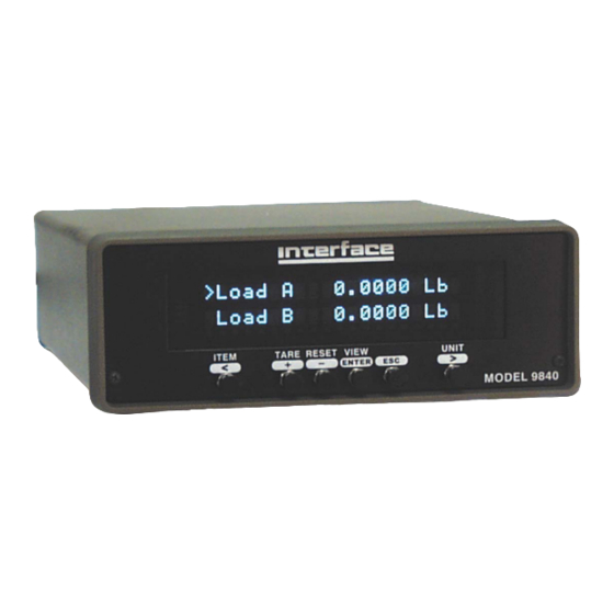
I N T E R F AC E M O D E L 9 8 4 0 V E R 6 . 0 . 2 QUICK START This section will help you get your Model 9840 set up and operating in just a couple of minutes. - Page 8 Each of these messages will be displayed for about 3 seconds. After that the front display will start showing the current readings from the sensor. MODEL 9840 FRONT PANEL The example above shows that Load A is 0.0000 Lb. The second line of the display shows text.
- Page 9 I N T E R F AC E M O D E L 9 8 4 0 V E R 6 . 0 . 2 The rightmost button will change the units that are being used. Repeated presses of this button will cycle through the list of units available for the currently displayed item.
-
Page 10: Run Mode
I N T E R F AC E M O D E L 9 8 4 0 V E R 6 . 0 . 2 RUN MODE The Model 9840 has three modes of operation, Run mode, Setup mode, and System Calibration mode. At power-on it will be in Run mode. -
Page 11: Item Button
Shows state of each switch, 1 for on, 0 for off, dash for disabled, asterisk for source error. All of these measurements are acquired by the Model 9840 at all times with torque measurements acquired when a torque cell is attached to a channel and load measurements acquired when a load cell is attached. -
Page 12: Reset Button
Pressing “Enter” will reset the currently displayed item. Pressing “Esc” will return to Run Mode without resetting anything. Note that all menu lists on the Model 9840 start with the “>“ symbol and that the Esc button will always back out of a menu without making any changes. -
Page 13: Print Button
The units used for printing will be the units last selected on the numerical display. The printer must be a serial printer that supports ESC/P protocol. Many Epson printers with serial ports are known to be compatible. Appendix B gives the pin assignments on the serial connector. -
Page 14: Setup Mode Summary
I N T E R F AC E M O D E L 9 8 4 0 V E R 6 . 0 . 2 SETUP MODE SUMMARY The table below summarizes the setup mode menus. Detailed information about each individual item is presented in the following sections. -
Page 15: Setup Mode
I N T E R F AC E M O D E L 9 8 4 0 V E R 6 . 0 . 2 SETUP MODE Setup mode is used to change the setup of the Model 9840. To enter setup mode press the two end buttons at the same time ( “<“ and “>“ ). The row of four buttons will now function as indicated by the lower set of labels (Plus, Minus, Enter, and Escape). -
Page 16: Entering Numerical Data
I N T E R F AC E M O D E L 9 8 4 0 V E R 6 . 0 . 2 Entering Numerical Data At times you will need to enter numerical data into the Model 9840. The method is consistent in all cases. A number is presented on the left side of the display with an underline cursor. - Page 17 3. Full -- This entry specifies the value of source data (in the selected units) that will cause the Model 9840 to output positive full scale analog voltage (+10.0 volts). 4. Zero -- This entry specifies the value of source data (in the selected units) that will cause the Model 9840 to output zero analog voltage (0.0 volts).
-
Page 18: Sensor Select
This menu is used to manually select load or torque cell calibration data from a list stored in the Model 9840. When you select this menu on a 2 channel unit, you are asked to select Channel A or B. The cell serial number of the selected channel is displayed. Use either the left/right or plus/minus buttons to page through the list. -
Page 19: Sensor Delete
Press escape to return to the setup mode main menu. Press enter to select the displayed menu item. If you are re-calibrating a cell, the Model 9840 will recognize it using either the auto-id or a manually entered serial number. Any time you overwrite existing cell calibration data you will first be warned with the “Overwrite Data?”... -
Page 20: Cal Check
Selecting this item will run a calibration check on the cell attached to Channel A or B. The Model 9840 will measure the shunt value of the cell and compare it to the shunt value that was recorded when the cell was last calibrated. The rated load or torque and last calibration date for the cell are displayed followed by the currently measured shunt value and the shunt value that was recorded when the cell was calibrated. -
Page 21: Cal By Shunt Val
I N T E R F AC E M O D E L 9 8 4 0 V E R 6 . 0 . 2 set the torque. When the Model 9840 is reading the cell it will display the “Reading...”... -
Page 22: System Options
This setting has no effect on units that are not equipped with the printing option. 57.6 K baud is commonly used on older serial printers (Epson Stylus II), 230.4 K baud is used on more recent serial printers (Epson Stylus Color 600, Color 800). -
Page 23: Com Address
>>Filter Select There are two types of filters available on the Model 9840: Type I, and Type II. Type I filters are good for removing most kinds of noise but may leave some jitter on the end digits. Type II filters are more advanced and are optimized for the typical industrial environment. -
Page 24: Decimals Ch A/B
I N T E R F AC E M O D E L 9 8 4 0 V E R 6 . 0 . 2 >>Decimals Ch A/B This lets you set the maximum number of digits to the right of the decimal that are displayed or printed for load or torque, peak, and valley. -
Page 25: Remote Operation
REMOTE OPERATION Digital Inputs There are 4 digital inputs available on the Model 9840. They are accessible on the Digital I/O connector on the back panel (pins 9 - 16). These inputs are individually opto-isolated and include current limiting resistors. An input voltage anywhere from +4 to +22 volts DC may be used to obtain the “on”... -
Page 26: Communications Settings
The @ symbol initiates the command, all commands must begin with this symbol. The number 123 is the address of the Model 9840 which should respond to this command. This MUST be 3 digits so type 001 for unit one, and 026 for unit twenty-six. The command itself will be a sequence of letters such as the XYZ shown above. -
Page 27: Rs232 Run Mode Commands
The commands listed in this section mirror (and in some cases extend) the functions that are available from the front panel of the Model 9840 when it is in Run Mode. Each entry will include the name of the command, followed by a short description that includes the command format, an example that shows what you would type (shown in plain font) and what the Model 9840 would return (shown in italics). -
Page 28: Front Panel Display Command (F)
01 – C/M Front Panel Display Command (F) This command is used to set the front panel display of the Model 9840 to a desired combination of item and unit. There are five subcommands: Front panel View (FV), Front panel Set (FS), Front panel Alternate(FA), Front panel pointer control to line 1 (F1), and Front panel pointer control to line 2 (F2) . -
Page 29: Front Panel Pointer Control To Line 2 (F2)
(see above), and the repeat number must be 0,1, or 2. Choosing repeat 1 will make the Model 9840 send you the desired value once. Choosing repeat 2 will make the Model 9840 send the value at approximately 3 second intervals. Choosing repeat 0 will turn off any values that are being sent by a repeat 2 command. -
Page 30: Print Command (P)
(like the value command). Repeat 0 will turn off printing that was started with repeat 2. Repeat 3 will send one set of readings to the serial printer attached to the Model 9840 instead of to the RS232 terminal. Example:... -
Page 31: Freeze Display Command (X)
This command allows you to put a line of text on the front panel display of the Model 9840. The format is T (text), where text is the message that you want to display. The text is limited to the number of characters that can be shown on the front panel display. -
Page 32: Rs232 Setup Mode Command Summary
I N T E R F AC E M O D E L 9 8 4 0 V E R 6 . 0 . 2 RS232 SETUP MODE COMMAND SUMMARY @(addr) ╠═ ║ ╠═ ║ ╠═ (channel)(number) # ║ ╚═ (number) # ║... -
Page 33: Rs232 Setup Mode Commands
I N T E R F AC E M O D E L 9 8 4 0 V E R 6 . 0 . 2 RS232 SETUP MODE COMMANDS The commands in this section allow you to change the setup of the Model 9840. You will notice that these commands form a menu which approximately duplicates the Setup Mode menu used during setup of the Model 9840 from the front panel. -
Page 34: Analog Output Command (A)
I N T E R F AC E M O D E L 9 8 4 0 V E R 6 . 0 . 2 Analog Output Command (A) This command is used to view or set the analog output of the Model 9840. There are two subcommands Analog View (AV) and Analog Set (AS). -
Page 35: Sensor View Command (Sv)
I N T E R F AC E M O D E L 9 8 4 0 V E R 6 . 0 . 2 Example: @123SA Acknowledge: @123 This is the list of cell calibration data: Ch A = S/N 123456, 100.00 Lb 10.00 V Sensor View Command (SV) The Sensor View (SV) command has the format SV. -
Page 36: Calibration Command (C)
You must issue a CB command before trying calibration by mv/volt, masses, or shunt (CV, CM, CT or CS). While the Model 9840 is being calibrated using the remote commands, the front panel will show “CAL STARTED”. Pressing the front panel Esc button will cancel the calibration and issue a warning to the RS232 terminal. - Page 37 I N T E R F AC E M O D E L 9 8 4 0 V E R 6 . 0 . 2 command to stop this calibration. Another method of overwriting existing data is to delete the sensor first and then calibrate. The CB1 Command has been modified to accept the cell type but is still usable by older software.
-
Page 38: Calibration Escape Command (Ce)
I N T E R F AC E M O D E L 9 8 4 0 V E R 6 . 0 . 2 Calibration Escape Command (CE) The Calibrate Escape (CE) command is used to cancel a calibration that was started with the Calibrate Begin (CB) command. -
Page 39: Calibrate By Mv/V Torque And Volt Commands (Cmvt And Cmvv)
I N T E R F AC E M O D E L 9 8 4 0 V E R 6 . 0 . 2 Calibration by mV/V Mass 1 (CMVM1) command. The mass is entered using the following format: CMVM1(mass value)#. Entering this command will result in the unit prompting the user for the first milli-volt per volt command. -
Page 40: Calibrate By Masses Command (Cm)
I N T E R F AC E M O D E L 9 8 4 0 V E R 6 . 0 . 2 Calibration by mV/V Torque 1 (CMVT1) command. The torque is entered using the following format: CMVT1(torque value)#. Entering this command will result in the unit prompting the user for the first milli-volt per volt command. -
Page 41: Calibrate By Masses Point Command (Cmp)
Calibration Mass Point 1 (CMP1) command. The format is CMP1(mass)#. This will cause the Model 9840 to read 10 seconds of data from the load cell. These readings are averaged to obtain the first calibration mass reading. The example uses 0.0 Lb for the first mass. -
Page 42: Calibrate By Torque Command (Ct)
Calibration Torque Point 1 (CTP1) command. The format is CTP1(torque)#. This will cause the Model 9840 to read 10 seconds of data from the torque cell. These readings are averaged to obtain the first calibration torque reading. The example uses 0.0 LbI for the first mass. -
Page 43: Calibrate By Shunt Command (Cs)
I N T E R F AC E M O D E L 9 8 4 0 V E R 6 . 0 . 2 from the cell before entering this command since it will perform the shunt calibration measurement that is recorded for use with the calibration check command. The format is CTP0. -
Page 44: Limits Command (L)
This command allows you to view or set the 4 contact closure limit switches on the Model 9840. There are three subcommands Limit View (LiV), Limit Set (LiS), and Limit Reset (LiR). Note that changing a cell type on a channel will automatically erase limits tat were set for that channel. -
Page 45: Limit Setup Escape (Le)
I N T E R F AC E M O D E L 9 8 4 0 V E R 6 . 0 . 2 The limit number chooses which limit (1-4) you want to setup. The normal position should be set to 0 for normally open or 1 for normally closed. The enable should be set to 0 for disabled or 1 for enabled. -
Page 46: Limit Reset Command (Lir)
I N T E R F AC E M O D E L 9 8 4 0 V E R 6 . 0 . 2 @123LE Acknowledge: @123 Limit Setup Command Canceled Limit Reset Command (LiR) The Limit Reset (LiR) command is used to manually reset a latching limit that has been activated. -
Page 47: Option Auto-Identify Command (Oi)
I N T E R F AC E M O D E L 9 8 4 0 V E R 6 . 0 . 2 Example: @123OP9 Acknowledge: @123 Printer Baud Rate is 230.4K Option Auto-Identify Command (OI) The Option auto-Identify (OI) command is used to turn auto-identification of load cells on or off. -
Page 48: Option Com Baudrate Command (Ob)
The Option com Linefeed (OL) command turns on or off the generation of linefeed characters when the Model 9840 sends information to your RS232 terminal. The format is OL(0 or 1), where 0 turns linefeeds off, and 1 turns them on. -
Page 49: Display Options Command (D)
Display Options Command (D) The Display options command has 5 subcommands used to set options that effect the front panel display of the Model 9840. Display View Command (DV) The Display View (DV) command is used to return the current values of all the display options. -
Page 50: Display Count By Command (Dc)
Example: @123DTModel 9840 Acknowledge: @123 Text Message – Model 9840 Display Filter Window Commands (DW) The Display Filter Window (DW) command set enables and disables the filter window and allows the user to enter the unit and value of the filter window to use. There are two commands used to enable and set the filter windows. - Page 51 I N T E R F AC E M O D E L 9 8 4 0 V E R 6 . 0 . 2 Disabling the window sets this value to 0. The window, once enabled and set, will take effect immediately and will remain in effect until the window is disabled.
-
Page 52: System Calibration Mode
TECHNICIANS utilizing the proper precision devices to ensure the most accurate performance of the unit. 1. To enter system calibration mode, turn off the Model 9840. Hold down the two end buttons ( “<“ and “>“ ) while turning power back on. As soon as the display comes on you can release the buttons. -
Page 53: Appendix A -- Model 9840 Specifications
I N T E R F AC E M O D E L 9 8 4 0 V E R 6 . 0 . 2 APPENDIX A -- MODEL 9840 SPECIFICATIONS Transducer Interface Excitation Current Drive Push Button Shunt Internal Shunt Resistor... - Page 54 I N T E R F AC E M O D E L 9 8 4 0 V E R 6 . 0 . 2 Digital I/O Digital Inputs Interface Function Digital Outputs Function Quad-Limits Setup Quad-Limits Output Quad-Limits Source Serial Interface RS-232 Serial Setup/Output RS-485 Serial Setup/Output...
- Page 55 Package Size Case Material Mounting Hardware Environmental Operating Temp Storage Temp Relative Humidity The Model 9840 is compliant. M O D E L 9 8 4 0 2 lines by 20 characters > 4/Sec Automatic or manual ± 999,999 0 to 5 software selectable.
-
Page 56: Appendix B -- Cables And Connectors
I N T E R F AC E M O D E L 9 8 4 0 V E R 6 . 0 . 2 APPENDIX B -- CABLES AND CONNECTORS Load Cell Connectors DB9 Female Signal EXCITE - HI SENSE - HI CELL OUTPUT - HI CELL OUTPUT - LO... -
Page 57: Digital I/O Connector
3. The keylock input will be in the “unlocked” state if left unconnected. Tie this pin to GND to “lock” it. When locked the setup of the Model 9840 cannot be changed (you cannot enter Setup mode). 4. The encoder inputs are intended for use with a +12 VDC quadrature encoder. -
Page 58: Usb Connector
I N T E R F AC E M O D E L 9 8 4 0 V E R 6 . 0 . 2 USB Connector Name Description +5 VDC Data – Data + Ground M O D E L 9 8 4 0 P G 5 7 P U B . -
Page 59: Precision Shunt Calibration Resistors
I N T E R F AC E M O D E L 9 8 4 0 V E R 6 . 0 . 2 Precision Shunt Calibration Resistors This diagram shows the connection of the precision internal shunt resistors. The back panel switch (shown to the left of the two resistors) selects between 30 KΩ...
Need help?
Do you have a question about the 9840 and is the answer not in the manual?
Questions and answers