Table of Contents
Advertisement
Quick Links
Advertisement
Table of Contents

Related Manuals for Interface 9820


Summary of Contents for Interface 9820
- Page 1 Strain Gage Transducer Indicator Model: 9820 9820 Installation & User Manual...
-
Page 2: Table Of Contents
CALIBRATION INSTRUCTIONS ........13 PROGRAM MENU DIAGRAM ........17 WARRANTY..............18 FIGURES Figure 1 Model 9820 Front Panel View ....3 Figure 2 Model 9820 Rear Panel View ....3 Figure 3 Transducer Wiring ........4 Figure 4 Location of Jumpers and Adjustment Potentiometers ....... 4... -
Page 3: Description And Specifications
DESCRIPTION The Model 9820 is a microprocessor-based digital indicator capable of interfacing directly to a low level strain gage load cell transducer. An internal, high gain, fully-differential amplifier and a 4 1/2 digit analog-to- digital converter combine to accurately digitize the input signal. A 5V @ 60mA or 10V @ 120mA, short circuit protected, transducer excitation supply is also provided. -
Page 4: Installation And Wiring
INSTALLATION AND WIRING INSTALLATION The Model 9820 enclosure is designated for panel mounting in a 1/8 DIN cutout. The cutout dimensions are shown below. 1.772" 45mm (+0.024, -0.000) 92 mm 3.622" (+0.032, -0.000) To panel mount the 9820, perform the following steps. -
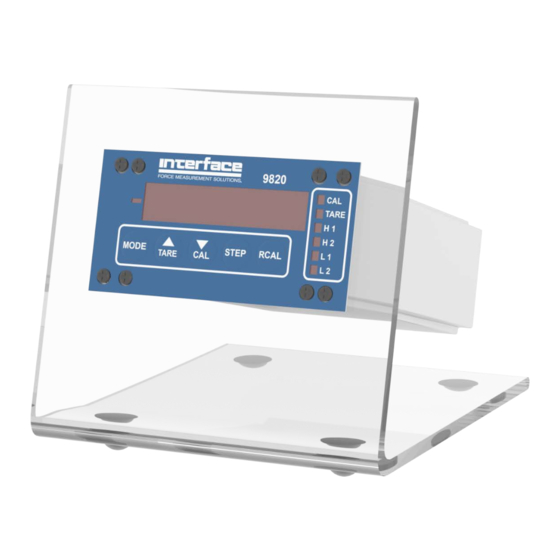
Page 5: Figure 1 Model 9820 Front Panel View
220/240V T250V 250mA Transducer, Analog Output and RCAL Connector AC Power Connector (8-pin Male 1.5mm Terminal Strip Connector) (3-prong grounded IEC connector) Figure 2. Model 9820 Rear Panel View Interface Inc, www.interfaceforce.com 13-60 Rev. D 9820 Installation & User Manual... -
Page 6: Figure 3 Transducer Wiring
Front Panel S1 MODE Switch Enable Transformer 1 2 3 4 Vexc Adjust 10V Analog Out FS Adjust Figure 4 . Location of Jumpers and Adjustment Potentiometers (Top View) Interface Inc, www.interfaceforce.com 13-60 Rev. D 9820 Installation & User Manual... -
Page 7: Figure 5 Location Of Rcal Jumper
(1) solder jumper here. Note: For use with an external RCAL resistor, remove internal RCAL resistor (see Figure 5). Figure 5 . Location of Jumper (Bottom View) Interface Inc, www.interfaceforce.com 13-60 Rev. D 9820 Installation & User Manual... -
Page 8: Switch And Function Definitions
TARE LED. Depressing S2 again will UNTARE the readout and extinquish the TARE LED. TARING is accomplished by storing the reading prior to TARING and subtracting this value from all subsequent readings. Interface Inc, www.interfaceforce.com 13-60 Rev. D 9820 Installation & User Manual... - Page 9 RCAL reading is generated (Reference Figure 6). Front Panel Switch Disable Jumper (Reference Figure 5) Jumper 1, when removed, disables the CAL Switch (S3). Jumper 2, when removed, disables the MODE Switch (S1). Interface Inc, www.interfaceforce.com 13-60 Rev. D 9820 Installation & User Manual...
- Page 10 SPH1 and SPH2 values before deactivating their respective LEDs. The maximum value of hysteresis is 99 counts while the minimum is 00 counts. Interface Inc, www.interfaceforce.com 13-60 Rev. D 9820 Installation & User Manual...
- Page 11 The maximum value is initialized to -99,999 and the minimum value to 99.999 each time the TARE switch (S2) is depressed, whether to TARE or UNTARE the readout. Interface Inc, www.interfaceforce.com 13-60 Rev. D 9820 Installation & User Manual...
-
Page 12: Operating Instructions
Depressing S4 will select the next least significant digit position for updating. The digit being updated will be flashing. Using S2, S3, and S4, set Set Point High 1 to the desired value. Interface Inc, www.interfaceforce.com 13-60 Rev. D 9820 Installation & User Manual... - Page 13 7. Depress MODE (S1) switch once. The text CAL followed by the current CAL number will be displayed. Repeat Step 1 to set the CAL number. The maximum CAL number is 99,999. Interface Inc, www.interfaceforce.com 13-60 Rev. D 9820 Installation & User Manual...
- Page 14 9. Depress MODE (S1) switch once. The instrument will exit the Mode Selection Sequence and enter the normal operating mode (i.e. monitoring the input signal) This is the end of the PROGRAM INSTRUCTIONS. Interface Inc, www.interfaceforce.com 13-60 Rev. D 9820 Installation & User Manual...
-
Page 15: Calibration Instructions
CALIBRATION INSTRUCTIONS The Interface Model 9820 can be calibrated using (2) different methods. 1. The first method uses actual or simulated ZERO and FULL SCALE (FS) inputs. Actual inputs may come from a strain gage transducer loaded with calibrated weights. Simulated inputs may come from a strain gage bridge simulator. - Page 16 9 and 11 are performed. TARING the display does not change the scale factor (slope value) calculated when Step 11 is completed. S3 has a 3 second delay feature to prevent inadvertent loss of calibration. Interface Inc, www.interfaceforce.com 13-60 Rev. D 9820 Installation & User Manual...
- Page 17 Example: If the RCAL resistor supplied with the instrument creates an output equivalent to 80% of a full scale 500 pound load, set the CAL NUMBER to 400.00, 0400.0 or 00400. Interface Inc, www.interfaceforce.com 13-60 Rev. D 9820 Installation & User Manual...
- Page 18 (slope value) calculated when Step 10 is completed. S3 has a 3 second delay feature to prevent the inadvertent loss of calibration. Interface Inc, www.interfaceforce.com 13-60 Rev. D 9820 Installation & User Manual...
-
Page 19: Program Menu Diagram
Depress Shifts Decimal Set dP Pt to the Left Depress RCAL Readout CAL Led Depress No Change & switch displays CAL turns on STEP Depress MODE OPERATE Interface Inc, www.interfaceforce.com 13-60 Rev. D 9820 Installation & User Manual... -
Page 20: Warranty
Interface, which are inconsistent or in conflict with the terms of this warranty (including but not limited to the limitations of the liability of Interface, as set forth above), shall not be binding upon Interface unless reduced to writing and approved by an officer of Interface, Inc. - Page 21 ADVANCED FORCE MEASUREMENT 7401 E. BUTHERUS DR. SCOTTSDALE, AZ 85260 TEL: (480) 948-5555 FAX: (480) 948-1924 www.interfaceforce.com...
Need help?
Do you have a question about the 9820 and is the answer not in the manual?
Questions and answers