
Subscribe to Our Youtube Channel
Related Manuals for Interface ITL


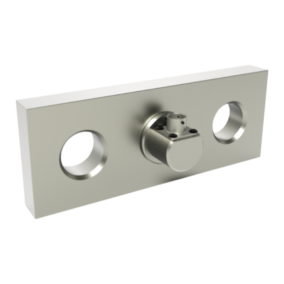
Summary of Contents for Interface ITL
- Page 1 OPERATOR INSTRUCTIONS FOR MODEL ITL TENSION LINK LOAD CELL Model ITL 7418 East Helm Drive • Scottsdale, Arizona 85260 • 480.948.5555 • www.interfaceforce.com Page 1 of 2...
- Page 2 TABLE OF CONTENTS OPERATING INSTRUCTIONS 1.1 Introduction........................1 Markings CE........................1 Electromagnetic Compatibility (EMC)................1 1.4 Installation and Operation....................1 1.5 Calibration..........................3 Warnings / Hazards......................3 1.7 Inspection and Repair......................4 WARRANTY 2.1 Warranty..........................5 7418 East Helm Drive • Scottsdale, Arizona 85260 • 480.948.5555 • www.interfaceforce.com Page 2 of 2...
- Page 3 OPERATING INSTRUCTIONS 1.1 Introduction This instruction manual refers to the Interface model ITL tension link telemetry options. Before installing or operating any Interface tension link, this and any reference documents should be read and understood. In compliance with the Machinery Directive, Interface tension link load cells will be supplied with the following documents: Instruction Manual and Calibration Certificate. Markings CE Each tension link will be marked with an individual serial number, CE label and the SWL (safe working load) of the tension link. 1.3 Electromagnetic Compatibility (EMC) The electromagnetic compatibility of the load cell device can only be assessed in conjunction with the entire installation, including its control systems. The machine builder who installs this partly completed machinery into a machine is responsible for compliance with the EMC directive.
- Page 4 • Ensure the tension link load cell does not experience torque or bending forces during operation. • The tension link load cell should only be loaded in tension using the ØC holes as shown in Figure 1. See Figure 2 for two common examples of installations. • For optimal performance a tight tolerance with the ØC loading holes is recommended. Figure 2 Figure 1 Electrical Checks The correct connection of a tension link to an instrument is critical to achieving and maintaining the performance and reliability of the load cell. • Tension link cabling must be kept away from high power cables and equipment, high output RF equipment and inductive loads and generators. Tension Link Output When setting up your tension link the following points should be acknowledged: • The zero load output given on the calibration certificate is the output of the tension link when no load is applied. This includes the removal of the load caused by any lifting accessories. • The load on an installed load link will comprise of the weight of your assembly (including sheaves, blocks, shackles, ropes, hooks etc.) and the active load (load lifted). Therefore, the output with no active load will be greater than the zero output indicated on the calibration certificate. Checks After Installation • With the tension link installed, check to make sure that the displayed output is not negative, as this may indicate either a fault or a compressive force is being applied to the tension link. (See Figure 1 on previous page). 7418 East Helm Drive • Scottsdale, Arizona 85260 • 480.948.5555 • www.interfaceforce.com Page 2 of 5...
- Page 5 • When applying load to the tension link, the output should increase in the positive direction. Use the calibration certificate for reference as to the output observed at certain loads. 1.5 Calibration All Interface tension link load cells are calibrated in traceable test machines to best simulate normal loading conditions. Our goal is to match the loading conditions that would be experienced in service but it is not possible to totally simulate the on-site structure for every tension link manufactured. It is for this reason that for optimum system accuracy, a calibration in the final assembly is recommended. On-site calibration should be performed with the instrument that is being used with this tension link load cell. Warnings / Hazards Tension links are highly stressed devices and commonly have safety factors between three and five times the rated capacity under static conditions. Fatigue applications and environmental factors can contribute to reducing this margin. The user should determine media effects on the exposed tension link materials. Where a corrosive environment is present, tension links can often be manufactured from corrosion resistant materials or, alternatively, isolation barriers can be employed between the corrosive environment and the tension link. The following points should be followed to avoid potentially hazardous situations: • Do not weld near to installed tension links, as leakage currents may destroy the tension link's electric circuits. • Tension links are sealed units which must not be dismantled. Damaged tension links should be returned to Interface for repair and re-calibration. • The accuracy of the system is dependent upon correct installation of the tension link. • Tension link load cells must not be subjected to shock loads, such as using a hammer to force an assembly together (fitting clevis pins into the mounting holes). • The tension link load cell should never be placed in a potential explosive environment unless the product is suitably certified (ATEX or IECEx). 1.7 Inspection and Repair Repair Interface reccomends that all prepared and service of tension link load cells be performed by Interface. 7418 East Helm Drive • Scottsdale, Arizona 85260 • 480.948.5555 • www.interfaceforce.com...
- Page 6 • Completion of the safety checks after installation. • Check output at zero load (shift in zero offset). Verify against calibration certificate. • Inspect to see if the tension link has been damaged/worn or chemically attacked (from a corrosive environment or lubricants etc.). Load measuring links are designed for many diverse lifting and weighing applications. http://www.interfaceforce.com IF IN DOUBT ABOUT ANY ASPECT OF THE SELECTION, INSTALLATION OR USE OF A TENSION LINK, CONTACT INTERFACE FOR ADVICE BEFORE INSTALLING CE Approvals European Directive 2006/42/EC BS-EN ISO 13849-1:2015 BS-EN ISO 13849-2:2015 WARRANTY WARRANTY All tension link load cell products form Interface Force Inc., ('Interface') are warranted against defective material and workmanship for a period of (1) one year from the date of purchase.
- Page 7 'Interface' warranty does not apply to defects resulting from action of the buyer such as mishandling, improper interfacing, operation outside of design limits, improper repair or unauthorized modification. No other warranties are express ed or implied. 'Interface' specifically disclaims any implied warranties of merchantability or fitness for a specific purpose. The remedies outlined above are the buyer's only remedies. 'Interface' will not be liable for direct, indirect, special, incidental or consequential damages whether based on the contract, tort or other legal theory. Any corrective maintenance required after the warranty period should be performed by 'Interface' approved personnel only. 7418 East Helm Drive • Scottsdale, Arizona 85260 • 480.948.5555 • www.interfaceforce.com Page 5 of 5...
Need help?
Do you have a question about the ITL and is the answer not in the manual?
Questions and answers