Advertisement
7401 E. Butherus Dr. / Scottsdale, Arizona 85260 / 1-800-947-5598 / www.interfaceforce.com
The Excitation Voltage and Output of the DMA are Jumper selectable. The Excitation voltage default jumper is set to 10 VDC and the output
The Excitation Voltage and Output of the DMA are Jumper selectable. The Excitation voltage default jumper is set to 10 VDC and the output
default jumper is set to ±10 VDC. If these settings need to be changed:
default jumper is set to ±10 VDC. If these settings need to be changed:
a.) Remove the bottom panel by carefully prying up on the side retention tabs.
a.) Remove the bottom panel by carefully prying up on the side retention tabs.
b.) Slide the PCB from the case.
b.) Slide the PCB from the case.
c.) For jumper pins in the upper center of board: (Output Setting)
c.) For jumper pins in the upper center of board: (Output Setting)
POWER
d.) For jumper pins in the lower left of board: (Excitation Setting)
d.) For jumper pins in the lower left of board: (Excitation Setting)
DC
POWER
DC
EXCITATION
Voltage
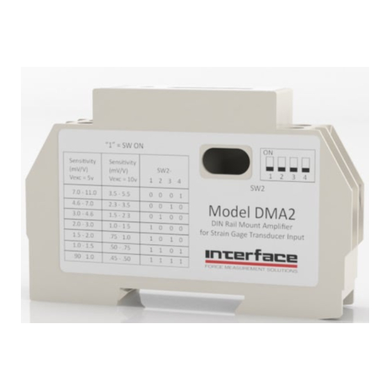
Once the jumper settings have been selected, the DIP switch (SW2) on the side of the unit must be set. Based upon the output of the load cell
Once the jumper settings have been selected, the DIP switch (SW2) on the side of the unit must be set. Based upon the output of the load cell
EXCITATION
Current
at full scale (in mV/V) and the excitation voltage of the load cell, set the four positions of SW2 using the settings table on the DMA or at the
at full scale (in mV/V) and the excitation voltage of the load cell, set the four positions of SW2 using the settings table on the DMA or at the
Voltage
bottom of this page.
bottom of this page.
Current
OUTPUT
Output 1
OUTPUT
Output 2
1. Connect a 10-28 VDC power supply to terminals #1 and #2.
1. Connect a 10-28 VDC power supply to terminals #1 and #2.
Output 1
2. Connect the –Excitation wire of the load cell to terminal #5.
2. Connect the –Excitation wire of the load cell to terminal #3.
Output 2
PERFORMANCE
3. Connect the +Excitation wire of the load cell to terminal #6.
3. Connect the +Excitation wire of the load cell to terminal #4.
Input Range
4. Connect the –Signal wire of the load cell to terminal #7.
4. Connect the –Signal wire of the load cell to terminal #7.
PERFORMANCE
Dynamic Response
5. Connect the +Signal wire of the load cell to terminal #8
5. Connect the +Signal wire of the load cell to terminal #8
Input Range
Zero Adjust Range
6. If the desired analog out from the DMA is 4-20 mA, then connect the appropriate voltmeter or instrumentation to terminals #1 (Ground) and
6. If the desired analog out from the DMA is 4-20 mA, then connect the appropriate voltmeter or instrumentation to terminals #1 (Ground) and #
Dynamic Response
Nonlinearity
3 (Iout 4-20 mA)
# 5 (Iout 4-20 mA)
Zero Adjust Range
Operating Temp.
7. If the desired analog out from the DMA is ±-5 VDC or ±10 VDC, then connect the voltmeter or instrumentation to terminals #1 (Ground) and
7. If the desired analog out from the DMA is ±-5 VDC or ±10 VDC, then connect the voltmeter or instrumentation to terminals #1 (Ground) and
Nonlinearity
Temp. effect on span
#6 (Vout ±5 or ±10)
#4 (Vout ±5 or ±10)
Operating Temp.
Temp. effect on span
DIMENSIONS
Width
For the 4-20 mA out setting, with NO load on the transducer, check the instrument or voltmeter and adjust the 4 MA adjustment screw on the
For the 4-20 mA out setting, with NO load on the transducer, check the instrument or voltmeter and adjust the 4 MA adjustment screw on the
DIMENSIONS
top of the DMA until 4mA shows on the instrumentation. Apply the full scale load to the transducer and adjust the 20 MA adjustment screw until
top of the DMA until 4mA shows on the instrumentation. Apply the full scale load to the transducer and adjust the 20 MA adjustment screw until
Height
Width
20 mA shows on the instrumentation. Remove the load from the transducer and if necessary, adjust the 4 MA screw again. Apply the full load to
20 mA shows on the instrumentation. Remove the load from the transducer and if necessary, adjust the 4 MA screw again. Apply the full load to
Depth
Height
the transducer and adjust the 20 MA screw until 20 mA is shown on the instrumentation. Repeat this process until the desired readings are
the transducer and adjust the 20 MA screw until 20 mA is shown on the instrumentation. Repeat this process until the desired readings are
Depth
achieved.
achieved.
TO CHANGE JUMPER SETTINGS:
For the ±5 VDC or ±10 VDC setting, with NO load on the transducer, check the instrument or voltmeter and adjust the COARSE ZERO or
For the ±5 VDC or ±10 VDC setting, with NO load on the transducer, check the instrument or voltmeter and adjust the COARSE ZERO or
FINE ZERO adjustment screw on the top of the DMA until 0 VDC shows on the instrumentation. Apply the full scale load to the transducer and
FINE ZERO adjustment screw on the top of the DMA until 0 VDC shows on the instrumentation. Apply the full scale load to the transducer and
1. Remove rear panel by carefully prying up on retention slots.
TO CHANGE JUMPER SETTINGS:
adjust the FINE SPAN adjustment screw until 5 VDC or 10 VDC shows on the instrumentation. Remove the load from the transducer and if
adjust the FINE SPAN adjustment screw until 5 VDC or 10 VDC shows on the instrumentation. Remove the load from the transducer and if
2. Slide PCB from case.
1. Remove rear panel by carefully prying up on retention slots.
necessary, adjust the FINE ZERO until 0VDC shows on the instrumentation. Apply the full scale load to the transducer again and adjust the
3. For jumper pins in upper center of board:
necessary, adjust the FINE ZERO until 0VDC shows on the instrumentation. Apply the full scale load to the transducer again and adjust the
2. Slide PCB from case.
FINE SPAN adjustment screw to 5 VDC or 10 VDC shows. Repeat this process until the desired readings are achieved.
FINE SPAN adjustment screw to 5 VDC or 10 VDC shows. Repeat this process until the desired readings are achieved.
±10 VDC Range = left and center pins jumpered
3. For jumper pins in upper center of board:
±5 VDC Range = right and center pins jumpered
±10 VDC Range = left and center pins jumpered
4. For jumper pins in lower left of board:
±5 VDC Range = right and center pins jumpered
10 V Excitation = bottom and center pins jumpered
4. For jumper pins in lower left of board:
5 V Excitation = top and center pins jumpered
10 V Excitation = bottom and center pins jumpered
5 V Excitation = top and center pins jumpered
Page 2 of 2
DMA2 SET UP & SCALING
DMA SET UP & SCALING
DMA SET UP & SCALING
DIN RAIL MOUNT AMPLIFIER
For Strain Gage Transducer Bridge Input
DIN RAIL MOUNT AMPLIFIER
For Strain Gage Transducer Bridge Input
SPECIFICATIONS
±10 VDC Range = the left and center pins are jumpered
±10 VDC Range = the left and center pins are jumpered
SPECIFICATIONS
±5 VDC Range = the right and center pins are jumpered
±5 VDC Range = the right and center pins are jumpered
10-28 VCD
10 V Excitation = the bottom and center pins are jumpered
10 V Excitation = the bottom and center pins are jumpered
5 V Excitation = the top and center pins are jumpered
5 V Excitation = the top and center pins are jumpered
10-28 VCD
Jumper selectable 5 or 10 VDC (default = ±10 VDC)
30 mA max
Jumper selectable 5 or 10 VDC (default = ±10 VDC)
30 mA max
EXAMPLE: A load cell with 3mV/V output and excitation voltage of 10 V = SW2 setting of 0010.
EXAMPLE: A load cell with 3mV/V output and excitation voltage of 10 V = SW2 setting of 0010.
Jumper selectable, bipolar, ±5 or ±10 VDC Full Scale (default = ±10 VDC)
4-20 mA, unipolar
Jumper selectable, bipolar, ±5 or ±10 VDC Full Scale (default = ±10 VDC)
4-20 mA, unipolar
5 to 50 mV for Full Scale Output using coarse and fine adjust
DC to 1000 Hz
5 to 50 mV for Full Scale Output using coarse and fine adjust
±50% Full Scale Output using coarse and fine adjust
DC to 1000 Hz
0.01% Full Scale
±50% Full Scale Output using coarse and fine adjust
32 to 158 °F, 0 to 70 °C
0.01% Full Scale
0.004%/°F
32 to 158 °F, 0 to 70 °C
0.004%/°F
.70 inch (17.5 mm)
3.90 inch (99 mm)
.70 inch (17.5 mm)
2.30 inch (58 mm)
3.90 inch (99 mm)
2.30 inch (58 mm)
Vexc = 5 V
Vexc = 5 V
7.0-11.0
7.0-11.0
4.6-7.0
4.6-7.0
3.0-4.6
3.0-4.6
2.0-3.0
2.0-3.0
1.5-2.0
1.5-2.0
1.0-1.5
1.0-1.5
0.90 – 1.0
0.90 – 1.0
7401 East Butherus Drive • Scottsdale, Arizona 85260 USA • Phone: 480.948.5555 • Fax: 480.948.1924
7401 East Butherus Drive • Scottsdale, Arizona 85260 USA • Phone: 480.948.5555 • Fax: 480.948.1924
7401 East Butherus Drive • Scottsdale, Arizona 85260 USA • Phone: 480.948.5555 • Fax: 480.948.1924
www.interfaceforce.com • Email: contact@interfaceforce.com • ORDER TOLL-FREE 800.947.5598
www.interfaceforce.com • Email: contact@interfaceforce.com • ORDER TOLL-FREE 800.947.5598
www.interfaceforce.com • Email: contact@interfaceforce.com • ORDER TOLL-FREE 800.947.5598
Model DMA
SET UP
SET UP
Model DMA2
SCALING
SCALING
Sensitivity (mV/V)
Sensitivity (mV/V)
Vexc = 10 V
Vexc = 10 V
3.5-5.5
3.5-5.5
2.3-3.5
2.3-3.5
1.5-2.3
1.5-2.3
1.0-1.5
1.0-1.5
0.75-1.0
0.75-1.0
0.50-0.75
0.50-0.75
0.45-0.50
0.45-0.50
SW2
SW2
1
1
2
2
3
3
4
4
0
0
0
1
0
0
0
1
0
0
0
0
1
1
0
0
0
0
1
1
0
0
0
0
1
1
0
0
0
0
0
0
1
0
1
0
1
0
1
0
1
1
1
1
0
0
1
1
1
1
1
1
1
1
1
1
Lconklin_072606/DMA_Setup
Lconklin_072606/DMA_Setup
Page 1 of 2
Page 2 of 2
Page 1 of 2
Advertisement
Table of Contents

Subscribe to Our Youtube Channel
Related Manuals for Interface DMA2


Summary of Contents for Interface DMA2
- Page 1 DMA2 SET UP & SCALING DMA SET UP & SCALING DMA SET UP & SCALING 7401 E. Butherus Dr. / Scottsdale, Arizona 85260 / 1-800-947-5598 / www.interfaceforce.com Model DMA SET UP SET UP DIN RAIL MOUNT AMPLIFIER The Excitation Voltage and Output of the DMA are Jumper selectable. The Excitation voltage default jumper is set to 10 VDC and the output The Excitation Voltage and Output of the DMA are Jumper selectable.
- Page 2 DMA2 SET UP & SCALING DMA SET UP & SCALING 7401 E. Butherus Dr. / Scottsdale, Arizona 85260 / 1-800-947-5598 / www.interfaceforce.com Model DMA2 Model DMA DIN RAIL MOUNT AMPLIFIER DIN RAIL MOUNT AMPLIFIER Model DMA2 For Strain Gage Transducer Bridge Input...
Need help?
Do you have a question about the DMA2 and is the answer not in the manual?
Questions and answers