Table of Contents
Advertisement
Quick Links
Advertisement
Table of Contents

Related Manuals for Interface GOLD STANDARD


Summary of Contents for Interface GOLD STANDARD
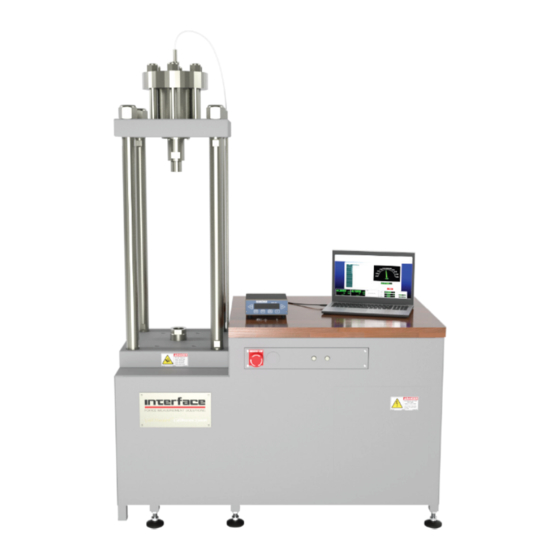
- Page 1 GOLD STANDARD® CALIBRATION SYSTEM Next Generation Force Measurement Solutions Load Calibration Frame Software and Configuration Manual 15-330 Rev. A The World Leader in Force Measurement Solutions™ 7418 East Helm Drive • Scottsdale, Arizona 85260 • 480.948.5555 • www.interfaceforce.com Page 1 of 45...
-
Page 2: Table Of Contents
TABLE OF CONTENTS Gold Standard Software Agreement ................4 License Agreement ....................... 4 Limited Warranty ......................4 Software Warranty ....................... 4 Hardware Warranty ...................... 4 Computer Equipment Warranty ................... 4 Customer Remedies ..................... 5 No Other Warranties ....................5 No Liability for Consequential Damages ............... 5 Cautions and Warnings .................... - Page 3 Main Menu ......................... 18 Analysis Menu ......................18 Tools Menu ......................... 19 Perform Calibration ....................19 Perform Creep ......................21 Auto Hydraulic Adjust ....................22 Performance Data ......................23 Compare Runs ......................24 Creep Data .........................24 Zero History Data......................24 Load vs. Error Plot ......................24 New File ........................24 WGoldCfg ........................25 Paths Screen .......................
-
Page 4: Gold Standard Software Agreement
INTERFACE SOFTWARE LICENSE AGREEMENT 1. GRANT OF LICENSE. Interface grants to the user the right to use one copy of the Interface Inc. software pro- gram (the “SOFTWARE”) on a single terminal connected to a single computer (i.e., with a single CPU). The user may not network the SOFTWARE or otherwise use it on more than one computer or computer terminal at the same time. -
Page 5: Customer Remedies
Interface product, even if Interface has been advised of the possibility of such damages. Because some states do not allow such exclusion of liability, the above limitation may not apply. -
Page 6: Cautions And Warnings
Cautions and Warnings Document Conventions The following international symbols will be used in this document with the appropriate meanings: WARNING This icon accompanies text dealing with hazards to personnel. When present, it indicates that a potential hazard to your personal safety exists if information stated within the “WARNING” paragraph is not adhered to or procedures are executed incorrectly. -
Page 7: Operating Safety Procedures
Operating Safety Procedures The following operating safety procedures are applicable to most testing systems. The user is required to read each item below and determine if it is applicable to the testing system for which this hydraulic power supply will be used. The user is also required to obtain and review all safety instructions on specific testing equipment used in the system. -
Page 8: Pressing Down Button With Load String Connected
Pressing down button with load string connected CAUTION If pressing down button with load string connected, the load cells may be overloaded. Effects of control adjustments CAUTION Do not make mechanical, or software adjustments to system components unless you know exactly how the adjustment will affect system operation. -
Page 9: Electrical Power Failures
Electrical power failures WARNING The failure or shutoff of electrical power to the testing system when pressure is being applied can cause considerable and unpredictable actuator reaction. Under these conditions, loss of electrical power on servo controlled systems will generally cause the actuator to stroke at maximum velocity in either direction or, if a device under test is attached, to apply full tensile or compressive force. -
Page 10: Introduction
When used in conjunction with the Interface 1600 or 1800 Series load cell standards, the system provides the user with an accurate tool for easy and quick calibration of load cells in tension or compression. -
Page 11: Basic System Specifications
GS-SYS Basic System Specifications General 4 column loading frame 150mm (6 inch) stroke Alignment swivel coupler/slack adapter Static calibration in tension or compression Top swivel coupler thread – 2”-12 male Bottom actuator thread – 2”-12 female 21MPa (3000 psi) hydraulic power unit Capacities 25,000 lbf. - Page 12 LVDT Omega LD620-7.5 with LD-tip Output +/- 5 VDC Measuring Range: +/-7.5mm (+/-0.3 inches) Excitation Voltage – 10-30 VDC Non-Linearity - <+/-0.2% FSO Feedback Sensor Control Load Cell bridge CAUTION DO NOT OPERATE the system with the Control Load Cell bridge cable disconnected, as the system will immediately seek maximum load.
-
Page 13: Gs-Sys Load Frame System Installation Checklist
GS-SYS Load Frame SYSTEM INSTALLATION CHECKLIST UNCRATING AND LOCATING EQUIPMENT Inspect all crates and boxes for damage, including the state of any shock and/or tilt sensors. Photograph any damage and save for possible insurance claim. Using a forklift, lift the crate and the load frame from the HEAVY END (actuator end and it is also marked on the crate) to prevent tipping. -
Page 14: Hydraulic Fluid
One 208-240 VAC, 30 amp, single phase circuit is needed for the hydraulic power supply. The plug supplied with the system is NEMA 6-20. Install the LVDT position sensor on top of the load cap using (2) cap screws (see Figure 3). Shipping gasket Installation Remove breather NOTE: Shipping gasket must filter for shipping and insert shipping gasket... -
Page 15: Test Set-Up
Please consult Interface Inc. if the connection on your cable does not match your load cell. In most cases, Interface Inc. can supply you with the one you need. Attach the 208/240 VAC 1 PH system power using the supplied mating connector (see Figure 7). - Page 16 9. Lower the piston to the bottom by pressing the Activate/De-activate Button Down Button down button and turn the pump off (See figure 8). 10. Install the threaded adapters to come within 5” of the slack adapter. Make the last connection between two threaded adapters and not the swivel stem (See figure 9).
- Page 17 CAUTION Ensure all threaded connections are engaged at least one (1) diameter length of the threads. CAUTION Threaded connections that bottom out must be backed off one full turn to avoid binding. 11. Turn on the pump and carefully guide the last threaded connection between the adapters. As the threads make initial contact, the slack adapter will raise the LVDT and stop when it is in the center of travel.
-
Page 18: Wcgold Software
• WGoldCfg is used to configure all WCGold program parameters. • WCalGold is used to calibrate the 9840 instrument using a transducer simulator such as the Interface Inc. Model CX-0610 or CX-0440. • WCGold is the main transducer calibration program. -
Page 19: Tools Menu
Tools Menu - Report Designer (Creates any of the following user generated custom printable reports. Any number of each type of report can be created. After a report is created and saved, it can then be printed from the corresponding Analysis Menu item.) - Performance Report - Fitted Curve Report - Standard Curve Report... - Page 20 The system will exercise the cell based on the number of cycles indicated by the ExerciseCycle parameter set in the AUTO.CFG parameter section of the WgoldCfg program. The system will first apply a load approximating the percent load indicated by the InitialLoad parameter. The output of the standard is compared against a nominal output based on the set point file settings.
-
Page 21: Perform Creep
FITTED DATA This will display the fitted curve output and error as well as the curve coefficients and standard deviation. A Printer button allows a hard copy report to be printed. These reports are created using the Report Designer found on the Tools menu from the main screen. FITTED PLOT This will produce a load vs. -
Page 22: Auto Hydraulic Adjust
AUTO HYDRAULIC ADJUST Allows manual control of command voltage for controlling hydraulic frame. Step 1: A set point file must be loaded before using Auto Hydraulic Adjust. Select Load Set Points button and select desired set point file. Step 2: Select desired voltage increment/decrement buttons to adjust command voltage as desired. -
Page 23: Performance Data
PERFORMANCE DATA If displayed from the Analysis menu: Select the desired .ZB zero file. Select the desired calibration run(s). If displayed from either Analysis menu or during calibration cycle: The system will now display the performance results. Output, Nonlinearity, Hysteresis and SEB parameters are compared against limits found in the GOLDINT.LMT or GOLDUSR.LMT files. -
Page 24: Compare Runs
COMPARE RUNS Compares the fitted curve of up to 3 prior runs with up to 3 current runs. Step 1: Select the desired curve type (Ascending, Descending or Combined). Step 2: Select the desired file. Step 3: Select the desired calibration run(s) for the previous calibration. Step 4: Select the desired calibration run(s) for the current calibration. -
Page 25: Wgoldcfg
WGOLDCFG The WGoldCfg program is used to configure all Interface Inc. software products. Along the top of the window, are tabs to select which configuration file to edit as follows: Paths Allows editing of program, data and report file storage locations. -
Page 26: Auto Configure Screen
Auto Configure - CALIBRATION SET POINT FILE CREATION When a new calibration sequence is desired or a calibration standard is recalibrated, a new calibration set point file is required. Following is the instruction for creating a file. When all of the required data has been entered in the Device Under Test information screen, select either TENSION or COMPRESSION for the mode of calibration. - Page 27 IMPORTANT! The above is valid for ascending points. Descending points created by this method will have ignored the hysteresis in the standard. It is recommended that desired descending points be included in the load column but then the automatic mV/V values be manually replaced by editing to the values from the calibration certificate.
-
Page 28: Calibration Set Point Button Function
• Standard Cal. Date: Date that the standard was calibrated. Located at the top center of the calibration data sheet. (NIST Test Date or Interface Test) • Cal Certificate: The traceability number for an individual standard. Located at the top center of the calibration data sheet. -
Page 29: Components
Components Figure 11 Figure 12 7418 East Helm Drive • Scottsdale, Arizona 85260 • 480.948.5555 • www.interfaceforce.com Page 29 of 45... -
Page 30: Protection Features
Component Control / Function Low Pressure Filter Fluid Level Drain Plug Reservoir Hour Meter High Pressure Filter Hydraulic Pressure Gage Accumulator Heat Exchanger Motor Temperature Gage Oil Fill Protection Features The hydraulic power unit has three methods of protection. The thermal overload relay on the motor starter protects the motor from damage due to overheating or overcurrent. -
Page 31: Maintenance
Maintenance Filter Maintenance The HPS (Hydraulic Power Supply) unit has three levels of filtration. The suction strainer is located inside the reservoir and should be cleaned and replaced every time the tank is drained for any reason. The strainer is made of non-rusting Stainless steel wire mesh and may be re-cleaned with solvent for reuse if desired. -
Page 32: Appendix
Appendix 7418 East Helm Drive • Scottsdale, Arizona 85260 • 480.948.5555 • www.interfaceforce.com Page 32 of 45... -
Page 33: System Block Diagram
7418 East Helm Drive • Scottsdale, Arizona 85260 • 480.948.5555 • www.interfaceforce.com Page 33 of 45... -
Page 34: Channel 9840-400-1-T Intelligent Indicator
• Quadrature encoder channel available Limits Quad-programmable • mV/V calibration PERFORMANCE • Compatible with Gold Standard® Calibration Systems Maximum Display Counts ±999,999 Display Update / sec. 15 Hz POWER OPTIONS Internal Resolution – bits Signal Input Range – mV/V ±4.5 •... -
Page 35: 9840 Intelligent Indicator
• Auto zero Current – MAX – mA • Front panel shunt calibration with two OUTPUTS Serial Interface RS232 duplex selectable resistors Output – Analog, 16 bit – VDC Scalable, ±10 • Display units conversion: Lb, Kg, N, Psi, Mpa, Klb, kN, Output –... -
Page 36: Model Sga Ac/Dc Powered Signal Conditioner
™ MODEL SGA AC/DC POWERED SIGNAL CONDITIONER FEATURES & BENEFITS STANDARD CONFIGURATION User selectable analog output ±10V, ±5V, 0-10V, 0-5V, • 0-20 mA, 4-20 mA 110 VAC, 220 VAC OR 18-24 VDC power • Switch selectable filtering 1 Hz to 5 kHz •... -
Page 37: 12802 Cable Drawing
7418 East Helm Drive • Scottsdale, Arizona 85260 • 480.948.5555 • www.interfaceforce.com Page 37 of 45... -
Page 38: 12679 Cable Drawing
7418 East Helm Drive • Scottsdale, Arizona 85260 • 480.948.5555 • www.interfaceforce.com Page 38 of 45... -
Page 39: Load Frame Dimensions
7418 East Helm Drive • Scottsdale, Arizona 85260 • 480.948.5555 • www.interfaceforce.com Page 39 of 45... -
Page 40: Wiring Diagram
7418 East Helm Drive • Scottsdale, Arizona 85260 • 480.948.5555 • www.interfaceforce.com Page 40 of 45... -
Page 41: Hydraulic Power Unit Diagram
7418 East Helm Drive • Scottsdale, Arizona 85260 • 480.948.5555 • www.interfaceforce.com Page 41 of 45... -
Page 42: Project Box For Load Calibration Frame Diagram
7418 East Helm Drive • Scottsdale, Arizona 85260 • 480.948.5555 • www.interfaceforce.com Page 42 of 45... -
Page 43: Cal Adaptors Drawing Dut & One Standard
DATE DRAW ROD 2.00-12 M THREADED COLLAR THREADED COLLAR ADAPTER 1020, 1120, 1220 BASE ADAPTER 2.00-12 F UNLESS OTHERWISE SPECIFIED DIMENSIONS ARE IN INCHES [mm] 7401 E. BUTHERUS DR. TOLERANCES ARE: SCOTTSDALE, AZ 85260 USA DATE CREATOR TITLE: CAL ADAPTERS 08/14/17 .XXX STD. -
Page 44: Cal Adaptors Drawing Dut & Two Standards
DATE DRAW ROD 2.00-12 M THREADED COLLAR THREADED COLLAR ADAPTER ADAPTER 1010, 1110, 1210 BASE ADAPTER ADAPTER 2.00-12 F SCALE 1:10 UNLESS OTHERWISE SPECIFIED DIMENSIONS ARE IN INCHES [mm] 7401 E. BUTHERUS DR. TOLERANCES ARE: SCOTTSDALE, AZ 85260 USA DATE CREATOR TITLE: CAL ADAPTERS... - Page 45 These products include load cells, torque transducers, multi-axis sensors, wireless telemetry, instrumentation and calibra- tion equipment. Interface, Inc., was founded in 1968 and is a US-based, woman-owned technol- ogy manufacturing company headquar- tered in Scottsdale, Arizona. ■...
Need help?
Do you have a question about the GOLD STANDARD and is the answer not in the manual?
Questions and answers