Advertisement
Available languages
Available languages
Quick Links
Operator's
Manual
Snow Thrower
11 Horsepower
Electric Start
30-inch
Dual Stage
Model 536.881112
CAUTION: Before using this
product, read this manual and
follow all of its Safety Rules and
Operating Instructions.
-I=..rT=...°l -
Manual del usario
Quitanieves
de 30 pulgadas
11 caballos
de fuerza
(hp)
Bietapico
Arranque
el_ctrico
Modelo 536.881112
PRECAUCION:
Antes de usar este producto,
lea este manual y siga todas las reglas de
seguridad e instrucciones de operaci6n.
Sears, Roebuck
and Co., Hoffman
Estates,
IL 60179 U.S.A.
F-011047L
www.sears.com/craftsman
Advertisement

Related Manuals for Craftsman 536.881112


Summary of Contents for Craftsman 536.881112
- Page 1 11 caballos de fuerza (hp) Bietapico Arranque el_ctrico Modelo 536.881112 PRECAUCION: Antes de usar este producto, lea este manual y siga todas las reglas de seguridad e instrucciones de operaci6n. Sears, Roebuck and Co., Hoffman Estates, IL 60179 U.S.A. F-011047L www.sears.com/craftsman...
- Page 2 SERVICE AND ADJUSTMENT BACK COVER LIMITED TWO-YEAR WARRANTY ON CRAFTSMAN SNOW THROWER For two years from the date of purchase, when this Craftsman Snow thrower is maintained, lubricated, and tuned up according to the operating and maintenance instructions in the owner's manual, Craftsman will repair, free of charge, any defect in material or workman- ship.
- Page 3 TRAINING Always wear safety glasses or eye shields during operation or while performing an ad- Read the operating and service instruction justment or repair to protect eyes from manual carefully. Be thoroughly familiar foreign objects that may be thrown from the with the controls and the proper use of the snow thrower.
- Page 4 13. Never operate the snow t hrower near en- Never store the snow thrower with fuel in closures, automobiles, window wells, the tank inside a building where ignition drop-offs, and the like without proper ad- sources are present such as hot water and justment of thesnow discharge angle.
- Page 5 Drive Clutch Forward Reverse Auger Clutch Auger Collector Engage Push To Engage Fuel FueI OilMixture Electric Starter Discharge DOWN Discharge UP Discharge LEFT Discharge RIGHT Weight Transfer Weight Transfer Transmission Ignition Key Lift Handle To Depress Pedal Insert To Run, Engage To Disengage Pull Out To Stop.
- Page 6 CONTENTS OF PARTS BAG (ACTUAL SIZE) 1 - Owner's Manual (not shown) 1 - Packet of Fuel Stabilizer (not shown) 1 - Warranty Card (not shown) Parts,foundin toolboxlocated on beltcover *Non-Assembly Knob (not actual size) 1 - Remote Chute 1 - Shift Lever Knob (not actual size) PARTS PACKED SEPARATELY...
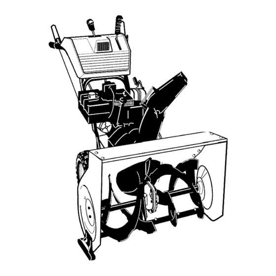
- Page 7 _,"_ _hVJl:11_ • & Figure 2 shows the snow thrower com- 4_lb WARNING: Always wear safety glasses or eye shields pletely assembled. while assembling snow References to the right or left hand side thrower. of the snow thrower are from the view- point of the operator's position behind TOOLS REQUIRED...
- Page 8 TO ASSEMBLE THE HANDLE 6. Install the fasteners that were re- CRANK ASSEMBLY moved in step 4. DO NOT tighten until all bolts are in place. 1. Cut tie holding shift rod to lower handle and move shifter to the first forward gear.
- Page 9 NOTE: If the cables have become dis- connected, connect cables as shown in Figure 7. Traction Drive Cable Auger Drive Cable Figure 7 How To Install The Knobs Speed Select Knob Remote Chute Knob Install the speed select knob to the 1.
- Page 10 How To Install The Speed Control 1. Put the speed select lever into the sixth gear position. 2. Attach the speed control rod (end with 90 °bend) to the speed select Speed Select bracket with washer and cotter Speed Lever pin.
- Page 11 _,,-,I,,',] =I _vj I--I _-I How To Set The Skid Height The snow thrower is equipped with height adjustable skids mounted on the outside of the auger housing. See Figure 13. To adjust the height of the skids, see "How To Adjust The Height Of The Skids"...
- Page 12 [o] -.l_1 :_±'1 / [o]_ KNOW YOUR SNOW THROWER READ THIS OWNER'S MANUAL AND SAFETY RULES BEFORE OPERATING YOUR SNOW THROWER. Compare the illustrations with your SNOW THROWER to familiarize yourself with the location of various controls and adjustments. Save this manual for future reference.
- Page 13 [o] -.l_1 :_±'1 / [o]_ and far. Pull the remote chute le- The operation of any snow thrower can result in foreign objects being thrown ver back to discharge the snow down. into the eyes, which can result in se- vere eye damage.
- Page 14 [o] -.l_1 :_±'1 / [o]_ HOW TO USE THE WHEEL LOCKOUT The left wheel is secured to the axle with a lockout pin. See Figure 17. The unit was shipped with the lockout pin in the locked position. For ease of maneu- verability in light snow conditions, dis- connect the lockout pin as follows.
- Page 15 [o] -.l_1 :_±'1 / [o]_ IFORNIA AND US EPA EMISSION premium, or reformulated automo- REGULATIONS FOR ULGE ENGINES: tive gasoline. DO NOT use leaded Are certified to operate on regular un- gasoline. Make sure that the con- leaded gasoline. Includethe following tainer you pour the gasoline from is clean and free from rust or other for-...
- Page 16 [o] -.l_1 :_±'1 / [o]_ TO START ENGINE Do not turn key. Keep the second key in a safe place. (ELECTRIC STARTER, 4. Rotate choke knob clockwise to the EQUIPPED) choke ON position. Be sure that the engine has sufficient 5.
- Page 17 [o] -.l_1 :_±'1 / [o]_ TO START ENGINE WARM START If restarting a warm engine after a short (RECOIL STARTER) shutdown, leave choke at "OFF" and do not push the primer button. If the en- Be sure that the engine has sufficient gine fails to start, follow the Cold Start oil.
- Page 18 [o] -.l_1 :_±'1 / [o]_ to remove any item that may ARNING: Do not attempt become lodged in auger without taking the following precau- tions: • Release auger drive lever. • Move throttle lever to stop posi- tion. • Remove (do not turn) ignition key.
- Page 19 CUSTOMER RESPONSIBILITIES SERVICERECORDS Every Every Every Fillindates asyou Before Each Before SERVICE complete r egular Each service. Often Hours Hours Hours Season Storage DATES iiiiiiiiiiiiiiiiiiiiiiiiiiiiiiiiiiiiiiiiiiiiiiiiiiiiiiiiiiiiiii ili!i!;! Change Engine Oil iiiiiiiiiiiiiiiiiiiiiiiiiiiiiiiiiiiiiiiii ......:::::::::::::::::::::: Check Spark Plug iiiiiiiiiiiiiiiiiiiiiiiiiiiiiiiiiiiiiiiii Check Fuel Check Cable Adjustment See Cable Adjustment) iiiiiiiiiiiiiiiiiiiiiiiiiiiiiiiiiiiiiiiiiiiiiiiiiiiiiiiiiiiiiij i i!
- Page 20 PRODUCT SPECIFICATIONS HORSEPOWER 11 HP DISPLACEMENT 21.82 cu, in. GASOLINE 4 quarts CAPACITY (unleaded) Figure 19 OIL CAPACITY 5W30 CHAIN LUBRICATION (20 oz capacity) EVERY 25 HOURS 1. Position speed selector lever in first SPARK PLUG: Champion RJt 9LM (Gap ,030 in.) or (1) forward gear.
- Page 21 AUGER GEAR BOX 2. Remove the oil drain plug and the oil fill cap/dipstick. Drain the oil The auger gear box is lubricated at the into a suitable container. factory and should not require addition- al lubrication. If for some reason the NOTE: The oil will drain more freely when the engine is warm.
- Page 22 raise the adjustable skids. Tighten nect the spark plug wire and the mounting nuts. See Figure 23. ARNING: Always discon- place it where it cannot NOTE: For rocky or uneven surfaces, make contact with spark plug to pre- raise the front of the snow thrower by vent accidental starting when mak- moving the skids down.
- Page 23 BELT ADJUSTMENT 5. Have someone engage auger drive clutch. Check tension on belt (op- Traction Drive Belt posite idler pulley). Belt should de- flect about 1/2 inch (12.5 mm) with The traction drive belt has constant moderate pressure Figure 25). You spring pressure and does not require may have to move idler pulley more an adjustment.
- Page 24 from the engine pulley. Replace Remove the bottom panel. the auger drive belt with an original Bolt Bottom Panel factory replacement belt available from an authorized service center. 8. Install the new auger drive belt onto the auger drive pulley and onto pulley.
- Page 25 How To Remove plate is properly secured (see The Traction Drive Belt Figure 28). If the snow thrower will not move for- ward, check the traction drive belt for wear or damage. If the traction drive belt is worn or damaged, replace the belt as follows.
- Page 26 BELT GUIDE ADJUSTMENT position of fitting to hole in clutch le- ver. 1. Remove spark plug wire. 2. Have someone engage auger drive. "Z" Fitting 3. Measure the distance between the belt guide and belt. The distance should be 1/8 inch (3.175 ram) for guide.
- Page 27 TRACTION DRIVE CABLE ADJUSTMENT line outdoors, away from drive cable through the cable ad- WARNING: Drain the gaso- 5. Pushthe bottom of the traction fire or flame, justment bracket untilthe "Z" hook can be removed. 1. Remove the gas from the gas tank. Stand the snow thrower up on the 6.
- Page 28 HOW TO ADJUST OR REPLACE When aligned, attach the ball joint THE FRICTION WHEEL to the shifter rod. 5. Tighten the jam nut. How To Check The Friction Wheel 6. Install the bottom panel (see Figure 35). If the snow thrower will not move for- 7.
- Page 29 How To Replace The Friction Wheel If the friction wheel is worn damaged, the snow thrower will not move forward. The friction wheel must be replaced as follows. Bolt 1. Remove the gas from the gas tank. Stand the snow thrower up on the Wheel front end of the auger housing (4).
- Page 30 10. Remove the three fasteners that 16. Check the adjustment of the friction hold the friction wheel to the hub wheel. See "How To Adjust The Friction Wheel" in this section. (see Figure 41). 17. Make sure the friction wheel and the 11.
- Page 31 THE CARBURETOR pounds. Feeler Gauge If you think your carburetor needs ad- justing, see your nearest Craftsman Store. Engine performance should not be affected at altitudes up to 7,000 feet. For operation at higher elevations, con- tact your nearest Sears Store.
- Page 32 If you do not remove the gasoline, tank, fumes may reach an open use fuel stabilizer supplied with unit flame, spark or pilot light from a fur- or purchase Craftsman Fuel Stabi- nace, water heater, clothes dryer, lizer No. 3550. Add fuel stabilizer to cigarette, etc.
- Page 33 Stop engine immediately and impeller disconnect spark plug wire. Tighten all bolts and make all necessary repairs. vibration continues, have the unit serviced by a Craftsman service repairman. Unit fails to propel itself Drive belt ioose or damaged. Replace drive belt. Incorrect adjustment Adjust traction drive cable.
- Page 34 SEARS, ROEBUCK Federal and California Emission Control Systems Limited Warranty Small Off-Road Engines CALIFORNIA & US EPA EMISSION quired maintenance listed in your Owner's CONTROL WARRANTY STATEMENT Manual, but Sears, Roebuck and Co. will not deny warranty solely due to the lack of receipts The U.
- Page 35 ershall pay any charges formaking service Sears, Roebuck and Co. according to Subsec- calls and/or fortransporting theproducts tion 4 below. Any such part repaired or re- and from the place w here the inspection and/ placed under the ECS Warranty shall be orwarranty work i sperformed.
- Page 36 use shall not r educe Sears, Roebuck and Co. EMISSION-RELATED PARTS ECS Warranty obligations. INCLUDE THE FOLLOWING: 9.Unapproved add-on ormodified parts m ay 1. Carburetor Assembly and its Internal Com- not b eused t omodify orrepair aSears, Roe- ponents buck a nd C o. engine. Such u se voids this ECS a) Fuel filter Warranty and shall besufficient grounds for...
- Page 37 GARANTiA LIMITADA DE DOS AI;IOS PARA EL QUITANIEVES CRAFTSMAN Durante dos argosa partir de la fecha de compra, siempre que a este quitanieves Craftsman se le d_ mantenimiento, lubricaci6n y afinamiento de acuerdo con las instrucciones de operaci6n y man- tenimiento presentadas en et manual del propietario, Craftsman reparar&, sin cargo alguno, cual...
- Page 38 CAPACITACION combustible que se produce por el calor del motor y/o del sol. Lea atentamente las instrucciones sobre Para todas las unidades con motores de operaci6n y servicio que aparecen en el arranque el6ctrico, utilice cables de exten- manual. Familiaricese completamente si6n certificados por CSA/UL.
- Page 39 8. Cuando limpie, repare oinspeccione 19. N unca opere elquitanieves sinbuena visi- bilidad oiluminaci6n. Asegt_rese siempre unidad, asegt3rese deque labarrena/pro- pulsor ytodas l as partes m6viles se ha- detenet buena estabilidad, y sujete yah detenido. Desconecte elcable d ela firmeza el mango de la unidad. Camine; bujia ymantengalo alejado deesta para nunca corra.
- Page 40 B'_t] KtI-'] IMPORTANTE: Encontrara muchos de los simbolos siguientes en su unidad o en los impresos in- formativos que vienen con el producto. Antes de operar la unidad entienda y aprenda el objetivo de cada simbolo. Simbolos de control y operacion Despacio Rapido Arranque el_ctrico...
- Page 41 Simbolos de control y operacion Mezcla de combustible Combustible Aceite y aceite Descarga hacia Descarga hacia Descarga hacia la Descarga hacia la ABAJO ARRIBA IZQUIERDA DERECHA i' o] Transterencia de peso Transterencia de peso Llave de ignicibn Levante el mango Presione el pedal Insertar para marcha, para enganchar...
- Page 42 CONTENIDO DE LA BOLSA DE PARTES ('FAMANO REAL) 1 - Manual del Propietario (no se muestra) 1 - Paquete de estabilizador de combustible (no se muestra) 1 - Tarjeta de garantia (no se muestra) *Las partesque no necesitanensamblade seencuentran en lacaja de herramientas ubicada en la cubierta de ia correa.
- Page 43 La Figura 46 muestra el quitanieves gafas de seguridad o protecto- completamente ensamblado. DVERTENCIA: Siempre use res para los ojos mientras en- La referencia a los lados izquierdo y sambla el quitanieves. derecho del quitanieves se hace desde HERRAMIENTAS NECESARIAS la posiciSn del operador cuando este se 1 - Cuchillo para cortar la caja encuentra detr&s de la unidad.
- Page 44 COMO ENSAMBLAR EL MANGOY EL CONJUNTO DE LA MANIVELA Conexi6n en "Z" 1. Corte los amarres que sujetan la palanca de cambios al mango inferior y mueva la palanca a la primera velocidad de avance. 2. Corte y deseche el amarre de pl&s- tico que sujeta el conjunto de la ma- nivela.
- Page 45 NOTA: Si los cables se han desconec- tado, conectelos come se muestra en la Figura 51. Cable de Cable de propul- propulsi6n si6n de la barrena Figura 51 COMO INSTALAR LAS PERILLAS Y MANGOS 3. Apdete la tuerca contra la parte in- Mango de la palanca remota...
- Page 46 COMO INSTALAR LA VARILLA 6. Aseg_rese de que la palanca de velocidad funcione bien. Mueva la DE CONTROL DE VELOCIDAD palanca de velocidad a tray,s de todas las velocidades. 1. Coloque la palanca de velocidad en la posici6n del engranaje nQmero seis.
- Page 47 Deflector Posici6n deoperaci6n tubodedes-/_-_.--_ Pernosde cabeza de hongo _S ___--_ Reborde Arandelas Amarre Figura 56 FIJACION DE LA ALTURA DE LOS PATINES El quitanieves tiene patines de altura ajustable montados en la parte de atr&s del alojamiento de la barrena. Para ajustar la altura de los patines vea "C6mo ajustar la altura de los patines"...
- Page 48 CONOZCA SU QUITANIEVES Lea este manual del propietario y las reglas de seguridad antes de usar su quitanieves. Com- pare las ilustraciones con su quitanieves para familiarizarse con las posiciones de los diversos oontroles y ajustes. Guarde este manual para referencia en et futuro. Palanca de propulsi6n Palanca de propulsi6n Bot6n de...
- Page 49 La operaci6n decualquier quitanieves puede ocasionar que objetos extrai_os sean l anza- dos hacia l os ojos, Iocual podrfa resultar en Iesiones graves. Use siempre gafas dese- guridad oprotectores para l osojos m ientras opere e lquitanieves. Se recomiendan las gafas deseguridad tg=ndar olamascara deseguridad...
- Page 50 COMO USAR EL PASADOR DE ENGANCHE DE LA RUEDA La rueda izquierda va asegurada el eje con un pasador de enganche. Vea la Figura 61. La unidad rue enviada con el pasador de en- ganche en posici6n. Para facilitar la manio- bra de la unidad en condiciones de poca nieve, desconecte el pasador de enganche de ia manera siguiente.
- Page 51 TIPO DE COMBUSTIBLE ci6n adicional). AVISO: MOTORES QUE ESTAN CERTIFI- Nunca use productos de limpieza de motor o CADOS PARA CUMPLIR CON LAS ESTF carburador en el tanque de combustible, PULACIONES DE LAS NORMAS DE Io contrario podria causar daflo permanente. EMISION EN EL ESTADO DE CALIFORNIA Y DE LAS NORMAS FEDERALES DE EPA...
- Page 52 PARA ARRANCAR EL MOTOR ci6n. NO ROTE LA LLAVE. Mantenga la segunda Ilave en un lugar seguro. (arrancador eldctrico) Rote la manecilla de estrangulaci6n a la Asegt3rese de que el motor tenga suficiente posici6n estrangulaci6n 'q-OTAL" acelte. El motor de el quitanieves esta equi- (FULL).
- Page 53 PARA ENCENDER EL MOTOR ARRANQUE EN CALIENTE (retroceso manual) Si esta arrancando un motor caliente des- pues de un apag6n corto, deje el estrangula- Cerci6rese de que el motor tiene suficiente dor en "APAGADO" (OFF) y no pulse el aceite. Antes de encender el motor, asegt_re- bot6n cebo.
- Page 54 DVERTENCIA: No intente qui- tar ningt_n objeto que se haya atorado en la barrena sin tomar as precauciones siguientes: Suelte las palancas de propulsion de la barrena y de propulsion de traccibn. Mueva la palanca de control de la ace- leracion a la posicion parar.
- Page 55 RESPONSABILIDADES DEL CLIENTE REGISTROSDE SERVICIO Anotelas fechss s me- Antes Cada Cada Cada Csda Antes FECHA didaque completsel de ca- A me- tempo- servicio da uso nudo horas horas horas rada guardar SERVICIO Cambiar eI aceite del motor !i!i!i!i!i!i!i!i!i!i!i!i!i!i!i!i!i!i!i!i!i!i! Revisar la bujia !i!i!i!i!i!i!i!i!i!i!i!i!i!i!i!i!i!i!i!i!i!i! to_ _!! ................
- Page 56 I_VJr-4 _ii_ _1 hVJIl_ _it_o] ESPECIFICACIONES LUBRICACI6N DE LA CADENA - CA- DA 25 HORAS 1. Ponga la palanca de selecci6n de veloci- CABALLOS 11 HP dad en primera (1). FUERZA 2. Ponga el quitanieves de pie sobre el ex- CILINDRADA 21.82 cu.
- Page 57 Figura 65. A gregue aceite demotor S.A.E. en su lugar y apri@teto para que quede 5W30 amedida que sea necesario. Apriete seguro. Iatapa!varilla indicadora enforma segura 4. Llene lentamente el carter del motor con cada v ez que revise elnivel del a ceite. aceite S.A.E.
- Page 58 4. Afloje las tuercas de montaje que sujetan los patines de ajuste de altura. Para bajar Ia parte delantera del quitanieves, suba el arranque accidental del mo- ADVERTENCiA: Para prevenir los patines. Apriete las tuercas de mon- tor, siempre desconecte el ca- taje.
- Page 59 AJUSTES DE LA CORREA beria coder media pulgada (12,5 mm) con presi6n moderada Correa de propulsion (Figura 69). Puede que tenga que La correa de propulsi6n tiene una mover la polea guia mas de una presi6n de resorte constante y no re- vez para conseguir la tensi6n co- rrecta.
- Page 60 3. Quite e l panel inferior. Instale una correa de propulsion de la barrena nueva original de f&- Pemo Panel inferior brica que haya comprado en un centro de servicio autorizado. 8. Instale la correa de propulsion de la barrena nueva en la polea de miento propulsion yen la polea.
- Page 61 Modo de desmontar la correa de sujeta (Figura 72). propulsion Si el quitanieves no se mueve hacia adelante, aseg_rese de que la correa de propulsi6n no est@excesivamente desgastada o dafiada. Si Io est&, reempl&cela de la siguiente manera. 1. Desconecte el cable de la bujia. 2.
- Page 62 AJUSTES DE LA CORREA GUiA Accesorio "Z" 1. Quite el cable de la bujia. 2. Pida a alguien que ponga el propul- sor de la barrena. 3. Mida la distancia entre la guia de la correa y la correa. La distancia de- be ser de 1/8 de pulgada (3,175 mm) para la guia.
- Page 63 PROPULSION AJUSTES CABLE solina al aire libre, lejos de propulsion por el soporte de ajus- ADVERTENCIA: Vacie la ga- 5. Meta la parte inferior del cable de te del cable hasta que pueda sacar cualquier llama. 1. Vacie el tanque de gasolina. Levan- el gancho "Z".
- Page 64 AJUSTE O REEMPLAZO DE LA RUEDA DE FRICCION Anillo de resorte de fricci6n_ Revision de la rueda de friccion Si el quitanieves no avanza, revise la correa de propulsi6n per tracci6n, el ca- ble de propulsi6n o la rueda de fricci6n. Si la rueda de fricci6n est&...
- Page 65 Reemplazo de la rueda de friccion NOTA: Fijese especialmente en la posicion de las arandelas en el eje hexagonal. Si la rueda de fricci6n est& gastada o dafiada, el quitanieves no avanza. La rueda de fricci6n se debe cambiar de la siguiente manera. 1.
- Page 66 10. Quite los tres sujetadores que re- Revise el ajuste de la rueda de fric- tienen la rueda de friccion en el ci6n. Consulte "Ajuste de la rueda de fricci6n" en esta secci6n. cubo (consulte la Figura 85). 17. AsegQrese de que la rueda de fric- 11.
- Page 67 SEGURIDAD DE LA BARRENA cesita set ajustada, p6ngase en contacto Las barrenas estAn sujetas al eje de Ia ba- con su centro de servicio Craftsman mAs rrena con pernos de seguridad especiales. cercano, el cual tiene el equipo y la expe-...
- Page 68 Finalmente, NOTA: Una revisi6n o afinamiento anual reinstale Ia bujia y conecte el cable. hecho en un Centre de servicio Craftsman es una buena manera de asegurar que su quitanieves le brinde el maximo rendimiento OTRAS INDICACIONES Ia siguiente temporada.
- Page 69 Apriete todos los pemos y haga todas las reparaciones necesarias. Si la vibraci6n continEa, haga revisar la unidad por un tecnico especializado Craftsman. La unidad no se Correa de propulsi6n floja o Reemplace la correa de puede propulsar daSada, propulsi6n.
- Page 70 SEARS, ROEBUCK Garantia limitada de cumplimiento con el Sistema Federal de control de emisiones y con el sistema de control de emisiones del Estado de California Motores pequehos no aptos para carretera (off-road) CONTROL DE EMISIONES SISTEMA PARA EL CONTROL DE CALIFORNIA Y DE LA AGENCIA DE EMISIONES DEL FABRICANTE...
- Page 71 Sears, Roebuck and Co. o a Sears, Roebuck A. CAMPO DE APLICAOION: Esta garantia and Co. al 1-800-473-7247 (llamada gratuita de berA aplicarse a los motores peq ue5os para en E.U.A.). vehiculos off-road modelo 1995 y modelos de aSos posteriores en California (para otros es- NOTA IMPORTANTE tados, motores modelo 1997 y modelos de aSos posteriores).
- Page 72 Garantia SCE d eberA garantizarse per elresto aprobada per S ears, Roebuck and Co. p ara del P eriodo delamisma. utilizarse eneldesempeflo decualquier man- tenimiento o cambio delaGarantia SCE, la 3.Cualquier parte g arantizada yreIacionada cual se proporcionarA sin cargo alguno para e l con emisiones que seespecifique para c am-...
- Page 73 For repair of major brand appliances in your own home.,. no matter who made it, no matter who sold it! iiiiiiiiiii 1-800-4-MY-HOME SM Any,_me day night (,-800469-4663! iiiiiiiiiii www.sears.com iiiiiiiiiii TO bring in products such as vacuums, lawn equipment and electronics for repair, call for the location of your nearest Sears Parts &...
- Page 74 CRAFTSMAN 30" 11HP SNOW THROWER 536.881112 ENGINE 25-2 25-3 " 5 Ref.Drive Ref. Auger Housing Page ENG101A Part No. Description Part No. Description ENGINE 1501201 GUIDE, ROD BELT 2x97 BOLT, CARRIAGE 71060 WASHER, SPTLK 28x76 RETAINER, PUSH 710097 SCREW 710026...
- Page 75 CRAFTSMAN 30" 11HP SNOW THROWER 536.881112 ELECTRIC STARTER ES100A PaN No. Key No. Description 6218 MOTOR, STARTER 6216 SCREW 6217 SCREW 6219 CORD, STARTER F-011047L...
- Page 76 CRAFTSMAN 30" 11HP SNOW THROWER 536.881112 FRAME Ref. Auger Housing Page Ref. Drive Page Part NO. Description Part No. Desori_ion 1501055E701 COVER, BOTTOM 71060 WASHER, SPLIT 310169 SCREW 780055 SCREW, TAP 1501106YZ IDLER, AUGER 53704 SPRING, IDLER 711682 PIN, HAIR...
- Page 77 CRAFTSMAN 30" 11HP SNOW THROWER 536.881112 DRIVE Ref. Shift Yoke Ref. Frame Page Page -" Ref. Whee Page Ref, Wheel Page DR100A F-O11047L...
- Page 78 CRAFTSMAN 30" 11HP SNOW THROWER 536.881112 DRIVE Key No. Part No. Description 1501092 LF AXLE, SWING PLATE YZ 579851 CHAIN, ROLLER #42x19.00 334163 REARING AND RETAINER, ASSY 579858 WASHER 780055 SCREW, TAP 5/16-18x0.5 1501100 ASSY, HEX SHAFT 579868 CHAIN, ROLLER #36x18.00 LG...
- Page 79 CRAFTSMAN 30" 11HP SNOW THROWER 536.881112 AUGER HOUSING _85 480 523 _ _ Ref. Gear Case Page 525 526 524 AUGER103A F-011047L...
- Page 80 CRAFTSMAN 30" 11HP SNOW THROWER 536.881112 AUGER HOUSING Key No. Part No. Description 583146 PULLEY, 4L 8.40 OD 577400 SCREW, 5/16-18X.63 2001022 KEY, SQUARE 3/16 X 3/4 15x112 Nut, 1/4" -24 1501158 SPACER, FRICTION PULLEY 582957 YZ RETAINER, BALL BRNG...
- Page 81 CRAFTSMAN 30" 11HP SNOW THROWER 536.881112 GEAR CASE 327 _ 313_ 315 _ GEARt05A Part No. Description Part No. Description CASE, GEAR, RH 73905 KEY, WOODRUFF CASE, GEAR, LH 53737 BRNG, FL 910828 SCREW,1/4-2OX.75 583126 SHAFT, INPUT 71100 NUT,1/4-2O 48275...
- Page 82 CRAFTSMAN 30" 11HP SNOW THROWER 536.881112 WHEEL ASSEMBLY Ref, Drive Page SD1021 PaN No. Key No. Description 1501104 SHAFT, AXLE SPRKT & HUB 1501089 lx186 SCREW, 1/4-20X1.75 780029 NUT, 1/4-20 HEX NYLOCK 1501114 BEARING, AXLE 712120 FLATWASHER 1501139 BUSHING, WHEEL 1501020 TIRE &...
- Page 83 CRAFTSMAN 30" 11HP SNOW THROWER 536.881112 CHUTE Ref. Handle Assy 852-9 _r Housing Assy 852-1 852-6 852-12 852-3 CROD100A F-011047L...
- Page 84 CRAFTSMAN 30" 11HP SNOW THROWER 536.881112 CHUTE Key No. Part No. Description 852-1 1501076 YZ ASSEMBLY, YOKE & ROD 852-2 313431 WASHER, CURVED SPRING 852-3 1501067 GEAR, CHUTE ROTATION 9T 852-5 71082 PIN, COTTER 852-6 1501051V701 BRACKET, GEAR MOUNT 852-7...
- Page 85 CRAFTSMAN 30" 11HP SNOW THROWER 536.881112 DISCHARGE CHUTE 582_ Ref. Auger Housing Page C3100A F-011047L...
- Page 86 CRAFTSMAN 30" 11HP SNOW THROWER 536.881112 DISCHARGE CHUTE Key No. Part No. Description 761168E701 CHUTE, UPPER W/REMOTE 578088 SCREW, 5/16-18 X.75 71038 578088 SCREW, 5/16-18 X.75 6711 PLASTIC WASHER 71038 761169E701 CHUTE, LOWER W/REMOTE 586280 BOLT 71071 WASHER_ FLAT 71038...
- Page 87 CRAFTSMAN 30" 11HP SNOW THROWER 536.881112 HANDLE ASSEMBLY Ref, Engine Page HDL104A F-011047L...
- Page 88 CRAFTSMAN 30" 11HP SNOW THROWER 536.881112 HANDLE ASSEMBLY Part No. Description Part No. Description 760192E701 ASSY, HANDLE 71072 WASHER, FLAT 71007 SCREW 71046 NUT, HEX 7288 SCREW 579183 SPACER, SHIFT 71072 WASHER, FLAT 71034 NUT, HEX 71062 WASHER 585522 KNOB, SHIFT...
- Page 89 CRAFTSMAN 30" 11HP SNOW THROWER 536.881112 REMOTE CHUTE CONTROL ASSEMBLY Ref. Control Panel Page /_994 Ref. Engine Page Ref. Discharge Chute Page h,,, Ref. Discharge Chute Page 342858 F-011047L...
- Page 90 CRAFTSMAN 30" 11HP SNOW THROWER 536.881112 REMOTE CHUTE CONTROL ASSEMBLY Key No. Part No. Description 318468 SPRING_ TENSION RETURN 711666 WASHER, FLAT 310088 BOLT, 5/16-18 73787 WASHER, FLAT 302635 NUT, 1/4-20 313676 SCREW, 5/16-18 X .75 780066 BRACKET, CABLE CHUTE...
- Page 91 CRAFTSMAN 30" 11HP SNOW THROWER 536.881112 HEADLIGHT Ref. Control Panel Page Ref. Handle Page SD1029 Part No. Key No, Description 762343 LIGHT, HALOGEN 1501036 HARNESS, HEADLIGHT 57444 TIE, CABLE BRACKET 578921 901696 SCREW #8 X .50 901736 WASHER, FLAT F-011047L...
- Page 92 CRAFTSMAN 30" 11HP SNOW THROWER 536.881112 CONTROL PANEL Ref. Handle Assembly Page Ref. Handle Assembly Page Ref. Handle Assembly Page Ref. Handle 337139 J Assembly Page Pad No. Key No. Description CLUTCH HANDLE LH 578992 578993 CLUTCH HANDLE RH 579039...
- Page 93 30" 11HP SNOW THROWER 536.881112 DECALS NOTILLUSTRATED Part No. Description 761776 DECAL DANGER & FOOT DECAL DANGER CHUTE -HAND 761916 48x399 DECAL 11_0 CRAFTSMAN DECAL DANGER STRIPE 761078 DECAL REMOTECHUTETRACTENGAGE 48x2003 DECAL SPEED SELECT 48x2001 48x2002 DECAL AUGER ENGAGE 48x358 NAMEPLATE,...
- Page 94 CRAFTSMAN 4-CYCLE ENGINE MODEL NUMBER 143.021101 e_292 %_10 48 _ 370C F-O11047L...
- Page 95 CRAFTSMAN 4-CYCLE ENGINE MODEL NUMBER 143.021101 PART PART DESCRIPTION DESCRIPTION 35371 Cylinder Ass'y (2, 20, 72) 36896 Oil Dipper 27652 Dowel Pin 35375 Camshaft (MCR) 650820 Screw, 1/4-20xl/2" 33273A Blower Hsg Extension 31857 Oil Drain Extension 650128 Screw, 10-24xl/2" 30969...
- Page 96 CRAFTSMAN 4-CYCLE ENGINE MODEL NUMBER 143.021101 35395 Spark Plug (RJ1 9LM) 33013 Starter Bubble Cover 33369 Governor Gear Bracket 650760 Screw, 8-32 x 3/8" 659836 Screw, 10-24 x 1/2" 35985B Starter Cup 27882 Valve Spring Cap 29752 Nut & Lockwasher...
- Page 97 CRAFTSMAN 4-CYCLE ENGINE MODEL NUMBER 143.021101 PART DESCRIPTION 590749 Rewind Starter 590599A Spring Pin 590600 Washer Retainer 590679 590601 Washer 590680 Starter Dog 590412 Dog Spring 590682 Pulley & Rewind Spring Assy. 590750 Starter Housing Ass'y. 590535 Starter Rope (Length 98" x 9/64" dia.)
- Page 98 CRAFTSMAN 4-CYCLE ENGINE MODEL NUMBER 143.021101 - 25 F-O11047L...
- Page 99 CRAFTSMAN 4-CYCLE ENGINE MODEL NUMBER 143.021101 PART DESCRIPTION 640054 Carburetor (Inc1,184 of Engine Parts List) 631776A Throttle Shaft & Lever Assembly 631970 Throttle Return Spring 631778 Throttle Shutter 650506 Shutter Screw 632112 Choke Shaft & Lever Assembly 632174 Choke Shutter...
- Page 100 CRAFTSMAN 4-CYCLE ENGINE MODEL NUMBER 143.021101 F-O11047L...
- Page 101 CRAFTSMAN 4-CYCLE ENGINE MODEL NUMBER 143.021101 PART DESCRIPTION 33329E Electric Starter (110 Volt) 33451 Dust Cover 33842 Retainer Ring 33430 Spring Retainer 33431 Anti-drift Spring 37050 Nut & Gear 35449 Drive End Cap Ass'y (Incl. 7) 35450 "O" ring 35915...
Need help?
Do you have a question about the 536.881112 and is the answer not in the manual?
Questions and answers