Advertisement
Available languages
Available languages
Quick Links
I CRI:IFTSM I:1 N°I
Operator's
Manual
Snow Thrower
650 Series, 4-Cycle Engine
21-inch
Single Stage
Auger Propelled
Model 536.881410
CAUTION: Before using this product,
read this manual and follow all of its
Safety Rules and Operating Instructions.
Manual del usario
Quitanieves
650 Serie, 4-Ciclo
Motor
de 21 pulgadas
Monoetapico
Propulsado por barrena
Modelo 536.881410
PRECAUCION:
Antes de usar este producto,
lea este manual y siga todas las reglas de
seguridad e instrucciones de operaci6n.
Sears, Roebuck
and Co., Hoffman
Estates,
IL 60179 U.S.A.
1741476
www.sears.com/craftsm
an
Rev, 01 07-01-2007
Advertisement

Related Manuals for Craftsman 536.881410


Summary of Contents for Craftsman 536.881410
- Page 1 I CRI:IFTSM I:1 N°I Operator's Manual Snow Thrower 650 Series, 4-Cycle Engine 21-inch Single Stage Auger Propelled Model 536.881410 CAUTION: Before using this product, read this manual and follow all of its Safety Rules and Operating Instructions. Manual del usario Quitanieves 650 Serie, 4-Ciclo Motor...
- Page 2 ONE-YEAR WARRANTY ON CRAFTSMAN SNOW THROWER For one year from the date of purchase, when this Craftsman Snow thrower is maintained, lubricated, and tuned up according to the operating and maintenance instructions in the owner's manual, Sears will repair, free of charge, any defect in material or workmanship.
- Page 3 sible, then refuel such equipment on a capable amputating hands trailer with a portable container, rather WARNING: This snow thrower is and feet and throwing objects. than from a gasoline dispenser nozzle. Failure to observe the following safety in- Keep the nozzle in contact with the rim structions could result in serious injury.
- Page 4 9. Take all p ossible precautions when leaving Never touch a hot engine or muffler. the snow thrower unattended. Disengage theauger/ impeller, stop engine (motor), and remove key. 10. Do not start orrun engine inenclosed area, for use on sidewalks, WARNING: This snow thrower is driveways...
- Page 5 [.._o]l!.._ IMPORTANT: Many of the following symbols are located on your snow thrower or on litera- ture supplied with the product. Before you operate the snow thrower, learn and understand the purpose for each symbol. CONTROL AND OPERATING SYMBOLS Slow Fast Electric Start Engine Start...
- Page 6 Safety Warning Symbols DANGER DANGER WARNING Thrown Objects. Thrown Objects. Keep Bystanders Away. Keep Bystanders Away. IMPORTANT DANGER Read Owner's Manual Avoid Injury From DANGER Before Operating Rotating Auger. Keep Blockages must be cleared This Machine. Hands, Feet And only after shutting off the Clothing Away.
- Page 7 Deflector HOW TO REMOVE FROM THE CARTON 1. Locate and remove container of Craftsman 5W30 oil. 2. Locate all parts packed separately and remove from the carton. NOTE: Place fuel stabilizer in a safe place until needed for storage. 3. Remove and discard the packing...
- Page 8 HOW TO Lower Handle ASSEMBLE THE HANDLE 1. Remove the T-knobs and U-bolts Handle from the lower handle (Figure 2). 2. Put the upper handle in the operat- ing position. 3. Install the U-bolts and tighten the T-knobs. T-knob NOTE: Make sure that the cable is not U-bolts pinched between the upper and lower handle.
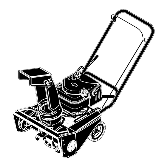
- Page 9 KNOW YOUR SNOW THROWER READ THIS OWNER'S MANUAL AND SAFETY RULES BEFORE OPERATING YOUR SNOW THROWER. Compare the illustrations with your SNOW THROWER to familiarize yourself with the location of various controls and adjustments. Save this manual for future reference. Auger Drive Lever Recoil...
- Page 10 [o_o_l 2. To stop throwing snow, release the auger drive lever. Manual before operating WARNING: Read Owner's machine. Never direct dis- charge toward bystanders. Stop the engine before unclogging discharge any snow thrower can result chute or auger housing and before WARNING: The operation of in foreign objects being...
- Page 11 Use tem of an engine while in storage. the fuel stabilizer supplied with the unit or purchase Craftsman Fuel NOTE: To avoid engine problems, the Stabilizer No. 3550. Make sure that fuel system must be emptied before the container you pour the gasoline storage for 30 days or longer.
- Page 12 [o_o_l HOW TO STOP THE ENGINE mable. Always use caution To stop the engine, push the stop ARNING: Gasoline is flam- when handling or storing switch to the OFF position. gasoline. CAUTION: To stop the engine, do not move the choke control to CHOKE •...
- Page 13 [o_o_l Slowly pull the recoil starter han- 6. As the engine warms up, move dle until resistance is felt and then choke control to 1/2 choke posi- pull rapidly to start the engine (See tion. When engine runs smoothly, move choke lever to OFF Position.
- Page 14 Use a clean-out tool to remove snow HOW TO CLEAR A CLOGGED DISCHARGE CHUTE from the auger housing. • Release the auger drive lever. with the rotating impeller in- WARNING: Hand contact • Pull out the key. side the discharge chute is •...
- Page 15 [o_o_l WET PACKED SNOW SNOW BANKS AND DRIFTS Move slowly into wet, packed snow. If In snow of greater depth than the unit, the wet, packed snow causes the auger use the same "jabbing" technique de- to slow down or the discharge chute be- scribed above.
- Page 16 CUSTOMER RESPONSIBILITIES SERVICERECORDS Fill in dates as you Before Every Every Every Every completeregular Each Each Before service. Often Hours Hours Hours Hours Season Storage Check Engine Oil Level Change Engine Oil Tighten All Screws and Nuts Check and Clean Spark Plug Clean and Inspect Spark Arrestor...
- Page 17 ENGINE SPECIFICATIONS GROSS TORQUE 6.50 ft-lbs DISPLACEMENT 190cc BORE 68mm (2.69 in.) STROKE 52mm (2.05 in.) GASOLINE 1.5 quarts CAPACITY (unleaded) OIL CAPACITY 5W30 (20 oz capacity) SPARK PLUG: Champion RJ19LM (Gap .030 in.) or equivalent VALVE Intake: 0.004-0.006 CLEARANCE: Exhaust: 0.009-0.011 ARMATURE...
- Page 18 1. Lift the rear of the snowthrower ENGINE tilt the unit forward. In the correct LUBRICATION position, the snowthrower will be Check the crankcase oil level before setting on the front of the auger starting the engine and after each eight housing.
- Page 19 ADJUST AUGER CONTROL CABLE The auger control cable was adjusted 6. Tighten the nut that holds the cable at the factory. If the auger will not en- tension spring. gage or disengage correctly, adjust the auger control cable as follows: 1.
- Page 20 HOW TO REMOVE THE TOP COVER There are no adjustments under the top cover. To clean the engine cooling sys- tem, follow the steps below to remove Cover Crank the cover. Assembly 1. Remove screws A that attach the rod support clamp the the top cov- er.
- Page 21 HOW TO ADJUST THE AUGER BRAKE The auger brake is adjusted at the fac- Auger Drive Lever Adjuster tory to assure safe operation of the snowthrower. If the auger brake needs an adjustment, follow the steps below: 1. To access the auger brake, tilt the front of the unit up.
- Page 22 HOW TO REMOVE THE AUGER DRIVE BELT The auger drive belt is made of special construction and must be replaced with an original equipment belt available from Sears. If the auger drive belt is damaged, the Idler Arm snowthrower will not discharge snow and will not move forward.
- Page 23 HOW TO REMOVE THE AUGER Slide the auger out of the right side of the auger housing (See 1. Remove the belt cover. See "How Figure 22). To Remove The Belt Cover". Slide the auger out of the bearing on the left side of the auger hous- Remove the auger drive belt.
- Page 24 If gasoline remains in the tank, or purchase Craftsman Fuel Stabi- fumes may reach an open flame, lizer No. 3550. Add fuel stabilizer to spark or pilot light from a furnace,...
- Page 25 TROUBLE CAUSE CORRECTION Difficult starting Defective spark plug. Replace spark plug. Drain and clean the fuel tank. Water or dirt in fuel system. Refill with fresh fuel. Engine runs erratically Blocked fuel line, empty gas Clean fuel line; check fuel tank, or stale gasoline, supply;...
- Page 26 (This page applicable in the U.S.A. and Canada only.) Sears, Roebuck and Co., U.S.A. (Sears), the California Air Resources Board (CARB) and the United States Environmental Protection Agency (U.S. EPA) Emission Control System Warranty Statement (Owner's Defect Warranty Rights and Obligations) California Resources Board...
- Page 27 Sears, Roebuck and Co. Emission Control Defects Warranty Provisions The following are specific provisions relative to your Emission Control Defects Warranty Coverage. It is in addition to the Sears engine warranty for non-regulated engines found in the Operating and Maintenance Instructions. 1.
- Page 28 Look For Relevant Emissions Durability Period and Air Index Information On Your Engine Emission Label Engines that are certified to meet the California Air Resources Board (CARB) Tier 2 Emission Standards must display information regarding the Emissions Durability Pe- riod and the Air Index. Sears, Roebuck and Co., U.S.A. makes this information avail- able to the consumer on our emission labels.
- Page 29 CRAFTSMAN 650 SERIES 21 INCH SNOW THROWER, 536.881410 DECALS Key No. Part No. Description 1741357 Decal, 6.50 ft-lbs / 21" 48x5536MA Decal, Choke 48x304MA Decal, Belt Instruction (inside cover) 761150MA Decal, Auger Control Lever 7014t MA Decal, Danger Auger (Foot)
- Page 30 CRAFTSMAN 650 SERIES 21 INCH SNOW THROWER, 536.881410 DRIVE COMPONENTS 1741476...
- Page 31 CRAFTSMAN 650 SERIES 21 INCH SNOW THROWER, 536.881410 DRIVE COMPONENTS Key No. Part No. Description 1501812MA Cover, Top 26x316MA Screw 1501814MA Base, Chute Rod 26x292MA Screw 1501815MA Cover, Chute Rod 1501911MA Primerbulb, 1501813MA Bracket, Engine Chute 1259MA Hose 780212MA Screw...
- Page 32 CRAFTSMAN 650 SERIES 21 INCH SNOW THROWER, 536.881410 AUGER COMPONENTS 1741476...
- Page 33 CRAFTSMAN 650 SERIES 21 INCH SNOW THROWER, 536.881410 AUGER COMPONENTS Key No. Part No. Description 1502011E549MA Frame, Motor Box 15X143MA 580251MA Retainer, Bearing 43846MA Bearing 302628MA Bolt 338965MA Pulley, Auger 26x263MA Screw 762277MA Cover, Left Belt 1501927MA Assembly, Auger Housing...
- Page 34 CRAFTSMAN 650 SERIES 21 INCH SNOW THROWER, 536.881410 HANDLE & DISCHARGE COMPONENTS 32 33 1741476...
- Page 35 CRAFTSMAN 650 SERIES 21 INCH SNOW THROWER, 536.881410 HANDLE & DISCHARGE COMPONENTS Key No. Part No. Description 762252E701MA Handle, Upper 762259MA Cable, Auger Drive 1501877MA U- Bolt 57171MA Knob 71037MA 311936MA Washer 762250E701MA Handle, Lower 762251 E701MA Lever, Auger Drive...
- Page 36 BRIGGS & STRATTON ENGINE MODEL 120502-0255-E1 I 1019 LABEL KIT I 287 _ ©© 684_ 524 C_ 307_ 728_ _ Assemblies include all parts shown in frames, 1741476...
- Page 37 BRIGGS & STRATTON ENGINE MODEL 120502-0255-E1 Part No. Description Part No. Description 697322 Cylinder Assembly 691270 Spring-Valve 399269 Kit-Bushing/Seat (Exhaust) 692194 Retainer-Valve (Magneto Side) ,299819 Seal-Oil 691997 Slinger-Governor/Oil (Magneto Side) 690548 Tappet-Valve 691449 Camshaft 493279 Sump-Engine 790285 Manifold-Intake 691160 Head-Cylinder .692555 Gasket-Intake ,692249...
- Page 38 BRIGGS & STRATTON ENGINE MODEL 120502-0255-E1 1058 OPERATOR'S MANUAL] 276_ 332_ 1005 977 CARBURETORGASKET 137@ 633@ 356_: 276_ 617% 633A 121 CARBURETOR OVERHAUL 334_ 633 @ 104<'_ 633A ® 404 C_ 505 ° Assemblies include all parts shown in frames, 1741476...
- Page 39 BRIGGS & STRATTON ENGINE MODEL 120502-0255-E1 PartNo. Description PartNo. Description 790283 Switch-Rocker 790536 Flywheel 691636 Screw 693010 Wire-Stop (Throttle Valve) 19069 Puller-Flywheel 493267 Shaft-Throttle 692524 Screw e691242 Pin-Float Hinge (Carburetor) 691182 Valve-Choke 690272 Washer 498593 Shaft-Choke (Governor Crank) 498975 Jet-Main 690664 Screw (Standard)
- Page 40 BRIGGS & STRATTON ENGINE MODEL 120502-0255-E1 1036 EMISSIONS LABEL 6161_ 1361 976@ ° 304 @ 592_ 58__ 469_ 689 _ 972_ 358 ENGINE GASKET SE_TT 9 _'_ 524_ 585_. I 1330 R EPAIR MANUAL I Assemblies include all parts shown in frames, 1741476...
- Page 41 BRIGGS & STRATTON ENGINE MODEL 120502-0255-E1 PartNo. Description Part No. Description *299819 Seal-Oil 95162 Clamp-Hose 697743 Starter-Rewind (Magneto Side) 691340 Screw .692249 Gasket-Cylinder Head (Muffler) .699472 Gasket-Breather 617.ee270344 SeaI-O Ring .692232 Gasket-Crankcase (Intake Manifold) Cover .493823 Spacer .399781 Seal-Oil (Includes 691855 Spring-Friction (PTO Side)
- Page 42 1741476...
- Page 43 Sears reparara sin cargo alguno, cualquier defecto en el material y mane de obra. Si este quitanieves de Craftsman es usado para prop6sitos comerciales o de arrendamiento, esta garantia sera valida solamente por 90 dias a partir de la fecha de compra.
- Page 44 pudiesen alcanzar alguna llama abier- yes tiene la capacidad de ampu- ta o chispas. ADVERTENCIA: Este quitanie- tar las extremidades y de lanzar Verifiquequeelquitanieves tengasufi- objetos con velocidad. No respetar las si- ciente combustible antes de cada uso, guientes instrucciones de seguridad pue- y deje un espacio adicional en el tan-...
- Page 45 gase e ntodo momento abuena distancia 15. No sobrecargue la capacidad del quitanie- delaabertura del tubo dedescarga. ves al intentar limpiar la nieve a una veloci- 4. Tenga mucho cuidado al o perar el q uitanie- dad demasiado r&pida. ves enoa traves deentradas deautos, 16.
- Page 46 MANTENIMIENTO quitanieves este en condiciones seguras de funcionamiento. ALMACENAMIENTO Guarde el quitanieves a una distancia fuentes de ignici6n o de aparatos domesti- Cbmo despejar tubos de descarga atascados cos que tengan llamas de encendido, tales como calentadores de agua y estufas, cadoras de ropa, etc.
- Page 47 [.,,_o]mEo::[..l IM PORTANTE: Muchos de estos simbolos est&n colocados en su quitanieves o est&n impresos en los manuales que vienen con el producto. Antes de operar el quitanieves aprenda y comprenda objetivo de cada simbolo. SlMBOLOS DE CONTROL Y OPERACION Despacio Rapido Arranque electrico...
- Page 48 SlMBOLOS DE CONTROL Y OPERACION Mezcla de combustible Combustible Aceite y aceite Descarga hacia Descarga hacia Descarga hacia la Descarga hacia la ABAJO ARRIBA IZQUIERDA DERECHA Llave de encendido Transferencia de peso Transferencia de peso Levante el mango Presione el pedal Insertar para marcba, para enganchar.
- Page 49 COMO SACAR EL QUITANIEVES LA CAJA Localice y retire la botella de aceite de motor Craftsman 5W30. Localice todas las piezas empacadas por separado y s&quelas de la caja. NOTA: Coloque el estabilizador de com- bustible en un lugar seguro haste que se necesite pare almacenar la unidad.
- Page 50 Instalacibn del mango superior Mango inferior Quite las perillas en "T" y los pernos en Mango sup_ "U" del mango inferior (Figura 2). Coloque el mango superior en la posi- ci6n de operaci6n. Instale los pernos en "U" y apriete las perillas en "T".
- Page 51 CONOZCA SU QUITANIEVES LEA ESTE MANUAL DE INSTRUCCIONES Y LAS REGLAS DE SEGURI- DAD ANTES DE OPERAR SU QUITANIEVES. Compare consu las ilustraciones QUITANIEVES para familiarizarse con la ubicaci6n de los diversos controles y ajustes. Guarde este manual para referencia futura. Palanca de propulsi6n de la barrena -- Deflector del tu-...
- Page 52 del propietario antes de operar de cualquier quitanieves puede ADVERTENCIA: Lea el manual DVERTENCIA: La operacion la maquina. Nunca dirija la des- provocar que objetos extrar_os carga hacia los transet_ntes. Pare el mo- sean lanzados con fuerza hacia sus tor antes de desobstruir el tubo de des- ojos, Io cual podria resultar en lesiones carga o el alojamiento...
- Page 53 NOTA: Se recomienda el uso de aceite sin- ANTES DE HACER ARRANCAR EL MOTOR tetico cuando la temperatura este por debajo de los 32 grados. El aceite sintetico 5W30 es ACEITE DE MOTOR: aceptable para cualquier temperatura. NOTA: Puede que el motor ya tenga algo mezcle aceite con gasolina.
- Page 54 Combustible No. 3550 de COMO PARAR EL MOTOR Craftsman. Asegt_rese de que el recipien- te que contiene la gasolina a utilizar, este Para parar el motor, empuje el interruptor limpio y sin 6xido u otros residuos. Nunca de parada a la posiciSn APAGADO.
- Page 55 guiente despues de cada trabajo de Jale lentamente manijade remoci6n de nieve. arranque manual hasta que sienta resistencia y entonces j&lela r&pida- 1. Deje que el motor (apagado) se enfrie mente para arrancar el motor unos cuantos minutos. (Figura 7). No suelte la manija inmedia- tamente despues de jalarla.
- Page 56 COMO DESPEJAR TUBOS DE Utilicelo para quitar la nieve atascada en el DESCARGA ATASCADOS alojamiento de la barrena. • Suelte la palanca de propulsi6n de la ba- mas comunes asociadas con el rrena. ADVERTENCIA: lesiones uso del quitanieves son las que •...
- Page 57 NIEVE SECA Y DE za a atascar el tubo de descarga, retirese un POCA PROFUNDIDAD poco y empiece una serie de movimientos cortos con el quitanieves, hacia adelante y La nieve que se acumule hasta profundi- hacia atr&s. Estos movimientos cortos en la dades de ocho pulgadas puede quitarse nieve (de cuatro a seis pulgadas), ayudar&n...
- Page 58 k_-' k k k_ RESPONSABILIDADES DEL PROPIETARIO REGISTROS DE SERVICIO Anote las fechas en Antes Cada Cada Cada Cada Cada que se hace manteni- de ca- A me- esta- Antes de miento regular da uso nudo horas horas horas horas cibn guardarlo Revisar el nivel de...
- Page 59 ___ _, _, _ _, o] MOTOR ESPECIFICACIONES TORSION BRUTO 8,8 Nm CILINDRADA 190 cc CALIBRE 68mm (2,69 pulg.) CARRERA 56mm (2,05 pulg.) CAPACIDAD DE 1.5 cuartos GASOLINA (sin plomo) CAPACIDAD DE ACEITE 20 onzas, 5W30 BUJiA: Champion RJt 9LM (Entrehierro 0,030pig.) JUEGODE Entrada: 0,004-0,006...
- Page 60 ___ _, _, _ _, o] LUBRICACION DEL MOTOR sici6n correcta es con el quitanieves descansando sobre la parte delantera Revise el nivel de aceite en el c&rter del ci- del alojamiento de la barrena. gL)eSal) antes de hacer arrancar el motor y Coloque una bandeja para drenar el despues de cada ocho (8) horas de uso con- aeeite debajo de la boca de aeeite (Vea...
- Page 61 AJUSTAR EL CABLE DE CONTROL DE LA BARRENA El cable de propulsi6n de la barrena fue ajustado en la f&brica. Si la barrena no en- gancha o desengancha correctamente, ajus- te el cable de propulsi6n de la barrena, de la manera siguiente: Afloje la tuerca que sujeta el resorte de tension...
- Page 62 COMOQUITARLA CUBIERTASUPERIOR No hay controles de ajuste debajo de la cubierta superior. Para limpiar el sistema _erior de enfriamiento del motor, siga los pasos manivela a continuaci6n para quitar la cubierta. de ajuste 1. Quite los tornillos A que sujetan la abrazadera de soporte de la varilla a la cubierta superior.
- Page 63 COMO AJUSTAR EL FRENO DE LA BARRENA El freno de la barrena es ajustado en la f&- Palanca de propul- Tuerca de si6n de la barrena brica para asegurar la operaci6n segura del ajuste quitanieves. Si el freno de la barrena necesi- tara ajuste, siga los pasos a continuaci6n: Para alcanzar el freno de la barrena, in- Brazo...
- Page 64 COMO SACAR LA CORREA DE PROPULSION DE LA BARRENA correa La correa de propulsi6n de la barrena est& construida especialmente para la unidad y debe ser reemplazada con una correa origi- nal para la unidad, disponible en su tienda Sears m&s cercana. Si la correa de propulsi6n de la barrena es- tuviera daSada, el quitanieves no descargar&...
- Page 65 Para sacar la correa de propulsion de Correa. de pro- la barrena de la polea del propulsor, pulsi6n de la. ba.rrena. mueva, el bra.zo guia. a. la.posici6n de en- ga.nche. Esto le da.r& un espacio libre entre la.polea del propulsor y el brazo de freno pa.ra,sa.ca.r la.correa de pro- Polea.
- Page 66 COMO SACAR LA BARRENA Deslice la barrena fuera del soporte de cojinetes en el lado izquierdo del aloja- Retire la cubierta de la correa. Consulte miento. "C6mo quitar la cubierta de la correa". 10. Para instalar la barrena, realice los pa- Saque la correa de propulsi6n de la ba- sos anteriores en orden inverse.
- Page 67 Craftsman NQm. 3550. expuesta, chispa o llama piloto de Aflada el estabilizador de combustible una caldera, calentador...
- Page 68 PROBLEMA CAUSA CORRECClON Dificultad para Bujia defectuosa. Reemplace la bujia defectuosa. arrancar Agua o suciedad en el sistema Vacie y limpie el tanque de de combustible, combustible; vuelva a Ilenar el tanque con una mezcla fresca de combustible. El motor funciona Linea de combustible bloqueada, Limpie la linea de combustible;...
- Page 69 (Esta p&gina es aplicable Onicamente en Estados Unidos de America yCanad&.) Sears, Roebuck and Co., U.S.A. (Sears), Junta de Recursos Ambientales de California (CARB) y Agencia de Proteccion Ambiental de los Estados Unidos (U.S. EPA) Declaracion de la Garantia del Sistema de Control de Emisiones (Derechos y Obligaciones del Propietario de la Garantia de Defectos) La Junta de Recursos Ambientales...
- Page 70 Provisiones de la Garantia de Defectos del Sistema de Control de Emisiones Sears 3. Sin Costo Las siguientes son provisiones especificas lativas a la Cobertura de Garantia de Defectos La reparaci6n o cambio de cualquier Parte del Sistema de Control de Emisiones. Es una Garantizada se Ilevar&...
- Page 71 Busque el Periodo de Durabilidad de Emisiones y la Informaci6n del indice de Aire Pertinentes en su Etiqueta de Emisiones del Motor Los motores que son certificados para cumplir con las Normas de Emisiones Etapa 2 de la Junta de Recursos Ambientales de California (CARB) deben mostrar la informaci6n referente al Perio- do de Durabilidad de Emisiones y al Indice de Aire.
- Page 72 Your Home For repair-in your home-of all major brand appliances, lawn and garden equipment, or heating and coolingsystems, no matter who made it, no matter who sold it! For the replacement parts, accessories and owner's manuals that you need to do-it-yourself. For Sears professional installation of home appliances and items like garage door openers and water heaters.
Need help?
Do you have a question about the 536.881410 and is the answer not in the manual?
Questions and answers