Table of Contents
Advertisement
OWNER'S
MANUAL
MODEL NO.
536.885020
Caution:
Read and Follow
All Safety Rules
and Instructions
Before Operating
This Equipment
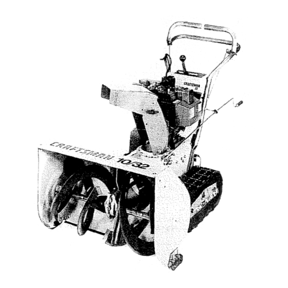
10 HORSEPOWER
32" DUAL STAGE
TRAC-PLUS
120V. ELECTRIC START
SNOW THROWER
° Assembly
+ Operation
• Maintenance
° Service and Adjustments
° Repair Parts
i i lll
iiilll
i
i
i lull
i
uumlu,_
i
lUlmu
III
,
lUllU
U.ll,i
II
im
i i,lu.m,_,,,i
SEARS, ROEBUCK AND CO., Chicago, IL 60684 U.S.A.
HHlul
u,m.
lure
HUm
I=um
=u,
,
=uHlllllu
Im
I
=umlll
=p,,,
,ll,
I I,
=l,=m,
Advertisement
Table of Contents

Related Manuals for Craftsman SEARS 536.88502


Summary of Contents for Craftsman SEARS 536.88502
- Page 1 OWNER'S MANUAL MODEL NO. 536.885020 Caution: Read and Follow All Safety Rules and Instructions Before Operating This Equipment i i lll iiilll i lull SEARS, ROEBUCK AND CO., Chicago, IL 60684 U.S.A. HHlul u,m. lure 10 HORSEPOWER 32" DUAL STAGE TRAC-PLUS 120V.
- Page 2 CAUTION: ALWAYS PLACE WIRE WHERE PREVENT ACCIDENTAL TRANSPORTING, SAFETY STANDARDS REQUIRE RISK IDF INJURY. YOUR SNOW ATTEMPT TO DEFEAT FUNCTION CIRCUMSTANCES. BEFORE USE • Read the Owner's Manual carefully. Be thor- oughly famifiar with the controls and the proper use of the snow thrower. Know how to stop the s_ow thrower disengage...
- Page 3 • Never operate the snow thrower closures, automobiles, window offs, and the like without proper adjustment the snow discharge angle. Keep children pets away. ® Never operate the snow thrower port speeds on slippery surfaces. and use care when backing. •...
-
Page 4: Warranty
_nd tuned-up according to the instructions in the owner's manual defect in material and workmanship If,this Craftsman Snow Thrower is used for commercfal or rental purposes, this warranty applies for only _0 days from the date ot purchase° This warranty does not cover the following:... -
Page 5: Table Of Contents
SAFETY RULES ... 2,3 PRODUCT SPECIFICATIONS CUSTOMER RESPONSIBILITIES WARRANTY ... 4 TABLE OF CONTENTS ... 5 INDEX ... ASSEMBLY ... 6-10 OPERATION ... 11-16 Adjustment: Auger ... Belt ... Beft Guide ... 22 Cable ... Carburetor ... 25 Friction Wheel ... 22 Spark Plug ... - Page 6 THIS SNOW THROWER IS EQUIPPED WITH "TRAC-PLUS" MOVES EFFECTIVELY WHEN ENGINE IS RUNNING If your snow thrower must be moved without the aid o! the engine, it will be easier to pull the snow thrower bank- ward by the handles, rather than pushing° On start up, the track drive system may be tight and will loosen up as the snow thrower is used..
-
Page 7: Assembly
Figure I shows the snow thrower in the shipping position Figure 2 shows the snow thrower completely assembled Reference to the right and left hand side of the snow thrower is from the operator's position at the handte_ TO REMOVE SNOW THROWER FROM CARTON (See Fig 1) - Page 8 CAUTION: tF YOU SNOW FROM ANY ROCKY OR UNEVEN SURFACES, RAISE THE FRONT OF THE SNOW THROWER BY MOVING SKIDS DOWN. THIS WILL HELP TO PREVENT ROCKS OTHER DEBRIS PI_.KED UP AND THROWN BY THE AUGER..H ,,lNI TO iNSTALL UPPER HANDLE CRANK...
- Page 9 J ,,,,, i _ ,,,,,,,, 1,1,,, • TO INSTALL THE SHIFTER LEVER KNOB • Stand the snow thrower up on the front of the auger housing, as shown in Fig 6A, • Cut the plastic tie which holds the shifter lever assembly to the shift bracket (Fig 6B).
- Page 10 iiiii lUU i iiiillU, UUl i i ii ii iiill TO iNSTALL CHUTE ASSEMBLY TO CHUTE FLANGE Remove the chute assembly from the carton • _Using a 1/2 inch wrench or adjustable wrench, re- move the three (3) nuts, Iockwashers, flatwashers and carriage bolts from the chute flange°...
-
Page 11: Operation
,,,,, =,=,,,, = =,,,,,,,,ll KNOW YOUR SNOW THROWER READ THIS OWNER'S MANUAL THROWER. Compare the illustrations with your snow thrower to familiarize yourself with the location of various controls and adjustments Save this manual for future reference, AUGER DRIVE LEVER CHUTE DEFLECTOR DISCHARGE CHUTE... - Page 12 ...,,,r, Ji nHnnn,Hu The operation of any snow thrower can result in foreign objects being thrown into the eyes, which can resutt in severe eye damage. shields while operating the snow thrower., We recommend standard safety glasses or wide vision safety mask tor over your glasses available at SEARS Retail or Catalog Stores.
- Page 13 TO USE WEIGHT TRANSFER In hard packed or heavy snow conditions, conventional snow throwers tend to ride up and leave uneven mounds of snow behind, For these conditions, your new tracked snow thrower has a unique weight transfer system (See Fig 13) designed to minimize ride-upr Stepping on the weight transfer pedal shifts more weight to the auger housing,, This weight transfer keeps the...
- Page 14 TO STOP ENGINE To stop engine, move the throttle control lever to STOP position and remove key Keep th,t key in a safe place.. The engine will not start without the key. TO START ENGINE (Electric Be sure that the engine has sufficient oil., The snow thrower engine is equipped with a 120 volt A C electric starter and recoil starter.
- Page 15 ==,= ,,,,,,,, , ,,,,, ,, , =,,=1,,i, CAUTION: NEVER RUN ENGINE IN- DOORS OR IN ENCLOSED, POORLY VENTILATED AREAS. HAUST CONTAINS CARBON OXIDE, AN ODORLESS AND DEADLY GAS° KEEP HANDS, FEET, HAIR CLOTHING AWAY FROM ANY MOVING PARTS ON ENGINE AND SNOW THROWER. WARNING: TEMPERATURE OF MUFFLER AND NEARBY AREAS MAY EXCEED 150 °...
- Page 16 SNOW THROWING TIPS • For maximumsnowthrower efficiency, ad_JStground speed, not throttle, If the track slips, reduce forward speed. The engine is designed to deliver maximum p_dormance at full throttle and should be run at trois power setting at all times.. Most efficient snow throwing is accomplished when the snow is removed immediately after it falls _For complete sn0w removal, slightly Overlap each...
-
Page 17: Belt
i ,ll,l,m, ii_J GENERAL RECOMMENDATIONS The warranty on this snow thrower does not cover items that have been subjected to operator abuse or negli- gence. To receive fullvalue fromthewarranty, must maintain snow thrower as instructed in this manual Some adjustments will need to be made periodically to properly maintain your snow thrower A!l adjustments in the Service andAdjustments of this manual should be checked at least once each... - Page 18 i iii ill ill llll NOTE: Any greasing or oiling of the above components can cause contamination of the friction wheet drive plate or friction wheel come in contact _th grease or oil, damage to the friction wheel will result. Should grease or oil come in contact with the disc dd_e plate or friction wheel, be sure to clean the plate and wheel thoroughly.
- Page 19 • • I I,H,IIIll i i i SPARK PLUG WIRE AND TIE BACK ! AWAY FROM THE PLUG BEFORE MAK- i CAUTION: ALWAYS DISCONNECT THE I ING ANY ADJUSTMENTS TO ADJUST SKIDS HEIGHT This snow thrower is equipped with two height adjust- ment skids, located on the outside of the auger housing (See Fig_ 23), Thes-e Skids_elevate the front of the snow thrower...
-
Page 20: Cable
SERVICE AN TO ADJUST THE CLUTCH CONTROL CABLES Periodiq adjustment of the cables may be required due to normal stretch and wear on the belts. To check Ior correct adjustment, the control lever must be in the full forward position, resting on the plastic bumper. - Page 21 fr IIH, I ,,',, Ill, SERVIC ... TO REPLACE BELTS The drive belts on this snow thrower are of special construction and should be replaced equipment belts available from your nearest SEARS Store or Service Center, You will need the assistance of a second person white replacing the belts,.
- Page 22 SERVICE AND TRACK DRIVE BELT If your snow thrower will not move forward check the track drive belt tot wear. If the track drive belt needs to be repl,_ced, proceed as follows: _isconnect the spark plug wire • Remove the belt cover,, •...
- Page 23 SERVICE AND ADJUSTMENTS nnn, l,,Hl,,,,,,,,,,,,,,l,,, TO REPLACE FRICTION Ifthesnowthrowerwitl not move forward, andthefriction wheel is worn or damaged, you need to replace it, as follows: (First allow the engine to cooL) AWAY FROM FIRE OR FLAME° CAUTION: DRAIN GASOLINE OUTDOORS I •...
- Page 24 SERVmCE ,u==, , =m,,= ,=u ,,,, TO REPLACE AUGER SHEAR The augers are secured to the auger shaft with special bolts (See Fig. 37) that are designed to break (to protect the machine) if an object becomes lodged in the auger housing.
-
Page 25: Carburetor
SERVICE AND ADJUSTMENTS TO ADJUST CARBURETOR The carburetor (See Fig. 40 and Fig. 42) has been pre-set atthe factory and readjustment should not be necessary. However, if the carburetor does need to be adjusted, proceed as follows: Close the high speed adjusting screw by hand •... - Page 26 Figure 42)r If you do not want to remove gasoline, stabilizer (such as Craftsman 33500) may be added to any gasoline left in the tank to minimize gum deposits and acids if the tank is almost empty, mix stablitizer with fresh gasoline in a separate container and add some to the tank.r...
- Page 27 SERVICE RECORDS Fill in dates as you com- After plete regular service First hours fuse ii,ul Check Engine Oil Leve! Change Er_gine Oi! Tighten All Screws and Nuts Check Traction Clutch Cable Adjustment (See Cable Adjustment) , ,. ,... , ... Replace Spark Plug .,,,,,, ...
-
Page 28: Friction Wheel
TROUBLE m,,u,i TROUBLE CAUSE Difficult starting Defective spark plug Water or dirt in fuel system '"B'i ke' "fuel Engine runs erratic Unit running on CHOKE Engine stalls i1,11 Engine runs erratic; Water or dirt in fuel system Loss of power Carburetor out of adjustment ,,n i, Excessive... - Page 29 NOTES...
- Page 30 CRAFTSMAN 32" TRAC-PLUS Handle Assembly Repair Parts F--- SNOW THROWER 50 13 17 48 536.885020 54 __ 48 ,. 44 43 43 44...
- Page 31 TRAC-PLUS CRAFTSMAN 32" REF. PART NO. PART NAME 3535 Cap, Push, 5/6 In 70985 Screw, 5/16-t8 x 3/4 In 3538 Pivot Pin 310421 Support, Control Panel Assembly 4049 Bumper 308012 Upper Handle 53861 Control Knob 70990 Screw, 5116-18 x 1-3/4 In...
- Page 32 CRAFTSMAN 32" TRAC-PLUS 52 51 50 53 SNOW THROWER 536.885020 60_'_ 68 67 Motor Mount Repair Parts 85 71...
- Page 33 70993 Carriage Bolt, 5116-1 71062 Lockwasher, 7'1012 Screw, Self-Tap, 3t8-16 x 1 In, 8220 Bolt, 5/!6-18 x 2-112 In, 307964 Engine, Craftsman, Model No, 143,8!6012 (See Er gine Repair Parts List) 85187 Belt Guard Plate 51438 Spacer 71393 Boll, 5/16-24 x 1 In 70991 Bolt, 5/16-18 x 3 In.
-
Page 34: Track
CRAFTSMAN 32" TRAC-PLUS !_._ B 31 26B 1415 SNOW THROWER 536.885020 Track Assembly Repair 12 tl Parts... -
Page 35: Chain
CRAFTSMAN 32" TRAC-PLUS REF,, I NO. I PART NO. PARTNAME 308161 Foot Pedal Assembly 10900 Bracket, L H 10901 Bracket, R H 6025 Spring, Tension Pal Nut, 1/2" 6001 Shoulder Bolt, 5/16-18 6888 Light Blue Decal ... 8 71037 Hex Nut, 5/16-18... - Page 36 _132"...
-
Page 37: Auger Shaft 1
TRAC-PLUS CRAFTSMAN 32" REF: PART NAME PART NO. Chute Extension 307921 71037 Hex Nut, 5/1648 71060 Lockwasher, 5/16 In 71071 Flatwasher, 11/32" 1441 Screw, 5/16-24 x 1-3/4 In 71147 Pan Head Slotted Bolt, 5/16-18 x 3/4 in 71038 Locknut, 5/16-18... - Page 38 CRAFTSMAN 32" TRAC-PLUS SNOW THROWER 536.885020 Gear Box Repair Parts REF.I NO. I PART NO. PART NAME Seal 1065 Housing LH 53743 Bearing, Auger Gear Box 20556 Square Key 53748 Flatwasher, 1" 73905 Woodruff #91 Key 53730 Worm Gear Gasket, Gear Box...
- Page 39 REWIND STARTER NOo 590630 Ref. Part Part 590630 Starter, Rewind 590599A Pin, Spring (Incl. No 7) 59O6OO Washer 59O651 Spring Assy., Brake B Dog 590627 Retainer 59O641 Dog, Starter 590601 Washer 59O628 Pulley 590451A Rope, Starter 59O629 Spring B Keeper Assy,. 590574 Handle, Mitten Grip (Not included with starter)
- Page 40 C_,FTSMAH 4=CY_=E ENGIN_ MODEL:143.816012 1_310 342_. _ODELendSERIAL NUMBERS HERE 370C...
- Page 41 CRAFTSMAN 4-CYCLE E HGINE Ref. Part Part Name 35371 Cytinder (InClr 65O820 Screw, Hex hd, shoulder, 114-20 x 112 34171 Nipple, Pipe, 5.1/2" 3O969 Cap, Oil drain 35319 Seal, Oii 27652 Pin, Dowel 35326 Baffle, Blower housing 650561 Screw, Hex washer hdo Durlok, 1/420...
- Page 42 4= ¢LE EHGINE Part PEtName 33013 Cover, Starter hole 650760 Screw, Pan hd° taptite, 8_32 x 3/8 35287 Hub, Starter 35446 Screen, Starter 29752 Nut e Lockwasher, 1/4-28 30705 Line, Fuel 2646O Clamp, Fuel line 65O665 Screw, Hex washer hd, thread cutting, 1/4-t5 x7/8 34156A Tank, Fuel (Incl.
- Page 43 NOTES...
-
Page 44: Engine
MODEL NO. ,885020 HOW TO ORDER REPAIR PARTS UnlU, i inlu SEARS, ROEBUCK AND CO., Chicago, IL 60684 307251 08t27t90 10 HORSEPOWER 32" DUAL STAGE TRAC=.PLUS 120V. ELECTRIC SNOW THROWER Each SNOW THROWER has its own MODEL NUMBER found on the motor mount frame+ Each ENGINE has its own MODEL found on the BLOWER...
Need help?
Do you have a question about the SEARS 536.88502 and is the answer not in the manual?
Questions and answers