Lexmark E320 - Printer - B/W Service Manual
Service manual
Hide thumbs
Also See for E320 - Printer - B/W:
- Setup manual (60 pages) ,
- User manual (11 pages) ,
- Quick reference (2 pages)
Table of Contents
Advertisement
Quick Links
Advertisement
Table of Contents

Related Manuals for Lexmark E320 - Printer - B/W


Summary of Contents for Lexmark E320 - Printer - B/W
- Page 1 Lexmark™ E32x 4500–00x 4500–1xx 4500–2xx • Table of Contents • Start Diagnostics • Safety and Notices • Trademarks • Index Lexmark and Lexmark with diamond design are trademarks of Lexmark International, Inc., registered in the United States and/or other countries.
- Page 2 You can purchase additional copies of publications related to this product by calling 1-800-553-9727. In other countries, contact your point of purchase. Lexmark, Lexmark with diamond design, MarkNet, and MarkVision are trademarks of Lexmark International, Inc., registered in the United States and/or other countries.
-
Page 3: Table Of Contents
4500 Table of contents Laser notices ......... . . vii Safety information. - Page 4 4500 Service checks ........2-63 Cold fuser service check .
- Page 5 4500 Diagnostic aids ........3-35 Diagnostic aids (E220/E321/E323) .
- Page 6 4500 Parts catalog ......... .7-1 How to use this parts catalog .
-
Page 7: Laser Notices
4500 Laser notices The following laser notice labels may be affixed to this printer as shown: Laser advisory label Class 1 laser statement label CLASS 1 LASER PRODUCT LASER KLASSE 1 LUOKAN 1 LASERLAITE APPAREIL À LASER DE CLASSE 1 TO IEC 60825 Laser notices... -
Page 8: Laser Notice
4500 Laser notice The printer is certified in the U.S. to conform to the requirements of DHHS 21 CFR Subchapter J for Class I (1) laser products, and elsewhere is certified as a Class I laser product conforming to the requirements of IEC 60825-1. - Page 9 4500 Avis relatif à l’utilisation de laser Pour les Etats-Unis : cette imprimante est certifiée conforme aux provisions DHHS 21 CFR alinéa J concernant les produits laser de Classe I (1). Pour les autres pays : cette imprimante répond aux normes IEC 60825-1 relatives aux produits laser de Classe I.
- Page 10 4500 Avisos sobre el láser Se certifica que, en los EE.UU., esta impresora cumple los requisitos para los productos láser de Clase I (1) establecidos en el subcapítulo J de la norma CFR 21 del DHHS (Departamento de Sanidad y Servicios) y, en los demás países, reúne todas las condiciones expuestas en la norma IEC 60825-1 para productos láser de Clase I (1).
- Page 11 4500 Laserinformatie De printer voldoet aan de eisen die gesteld worden aan een laserprodukt van klasse I. Voor de Verenigde Staten zijn deze eisen vastgelegd in DHHS 21 CFR Subchapter J, voor andere landen in IEC 60825-1. Laserprodukten van klasse I worden niet als ongevaarlijk aangemerkt.
- Page 12 4500 Huomautus laserlaitteesta Tämä kirjoitin on Yhdysvalloissa luokan I (1) laserlaitteiden DHHS 21 CFR Subchapter J -määrityksen mukainen ja muualla luokan I laserlaitteiden IEC 60825-1 -määrityksen mukainen. Luokan I laserlaitteiden ei katsota olevan vaarallisia käyttäjälle. Kirjoittimessa on sisäinen luokan IIIb (3b) 5 milliwatin galliumarsenidilaser, joka toimii aaltoalueella 770 - 795 nanometriä.
- Page 13 4500 Laser-melding Skriveren er godkjent i USA etter kravene i DHHS 21 CFR, underkapittel J, for klasse I (1) laserprodukter, og er i andre land godkjent som et Klasse I-laserprodukt i samsvar med kravene i IEC 60825-1. Klasse I-laserprodukter er ikke å betrakte som farlige. Skriveren inneholder internt en klasse IIIb (3b)-laser, som består av en gallium-arsenlaserenhet som avgir stråling i bølgelengdeområdet 770-795 nanometer.
- Page 14 4500 Japanese laser notice Chinese laser notice Service Manual...
- Page 15 4500 Korean laser notice Laser notices...
- Page 16 4500 Service Manual...
-
Page 17: Safety Information
4500 Safety information • The safety of this product is based on testing and approvals of the original design and specific components. The manufacturer is not responsible for safety in the event of use of unauthorized replacement parts. • The maintenance information for this product has been prepared for use by a professional service person and is not intended to be used by others. - Page 18 4500 Norme di sicurezza • La sicurezza del prodotto si basa sui test e sull'approvazione del progetto originale e dei componenti specifici. Il produttore non è responsabile per la sicurezza in caso di sostituzione non autorizzata delle parti. • Le informazioni riguardanti la manutenzione di questo prodotto sono indirizzate soltanto al personale di assistenza autorizzato.
- Page 19 4500 Pautas de Seguridad • La seguridad de este producto se basa en pruebas y aprobaciones del diseño original y componentes específicos. El fabricante no es responsable de la seguridad en caso de uso de piezas de repuesto no autorizadas. •...
- Page 20 4500 Informació de Seguretat • La seguretat d'aquest producte es basa en l'avaluació i aprovació del disseny original i els components específics. El fabricant no es fa responsable de les qüestions de seguretat si s'utilitzen peces de recanvi no autoritzades. •...
- Page 21 4500 Safety information...
-
Page 22: Preface
4500 Preface This manual contains maintenance procedures for service personnel. It is divided into the following chapters: 1. General Information contains a general description of the printer and the maintenance approach used to repair it. Special tools and test equipment are listed in this chapter, as well as general environmental and safety instructions. -
Page 23: General Information
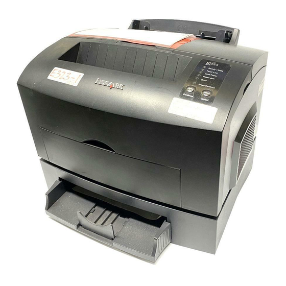
4500 1. General information The Lexmark™ E220/E32x series are letter–quality laser page monochrome desktop printers designed to fit into space critical environments and yet not sacrifice speed or ease of use. The E220/E32x attaches to an IBM Personal Computer or other... - Page 24 Paper guide Operator panel lights Front output door Optional 250-sheet tray • Lexmark E320 printer with 4MB of standard memory • Lexmark E322 printer with 8MB of standard memory • Lexmark E322n printer with standard Ethernet and 16MB of standard memory...
- Page 25 Lexmark E220 printer with 8MB of standard memory • Lexmark E321 printer with 8MB of standard memory • Lexmark E323 printer with 16MB of standard memory • Lexmark E323n printer with 16MB of standard memory and standard Ethernet General information...
-
Page 26: Model Differences
4500 There are some apparent differences in the E320/E322 series and the E220/E321/E323 series. The E220/E321/E323 series has: • a dark color in most geographies • two buttons on the operator panel • a bulge on the right side cover Internally, the E220/E321/E323 series has: •... -
Page 27: Printer Operation
4500 Printer operation Paper is held in a 150 page tray where it is picked by a center–fed D shape pick roller. The paper follows an L shape path as it moves through the printer. Images are created with toner on an optical photoconductor (OPC) drum within the toner cartridge. -
Page 28: Options
4500 Options The following options are available for the Lexmark E220/E32x. Note: Some options are not available in every country. Contact your point of purchase for options available in your country. Option E220 E320 E321 E322 E322n E323 E323n Tray 2... -
Page 29: Acronyms
4500 Acronyms Auto Sheet Feed ASIC Application-Specific Integrated Circuit Bill of Material Cyclic Redundancy Check CRLF Carriage Return Line Feed DIMM Dual Inline Memory Module DRAM Dynamic Random Access Memory External Network Adapter Electrostatic Discharge Field Replaceable Unit Host Based Printing HVPS High Voltage Power Supply LASER... - Page 30 4500 Service Manual...
-
Page 31: Diagnostic Information
4500–E320/E322 2. Diagnostic information Start Diagnostics (E320/E322) Note: For diagnostic information about models E220/E321/E323 see “Diagnostics (E220/E321/E323) ” on page 2-35 for more information. CAUTION: NEVER manually actuate or disable the top cover interlock switch and the printhead shutter actuator at the same time. -
Page 32: Operator Panel
4500–E320/E322 If a service error code appears while working on the machine, go to “Service error codes ” on page 2-11 and take the appropriate action. Operator panel The E320/E322 operator panel consists of six indicator lights and one button. The information provided by the six lights is classified into three groups: •... -
Page 33: Status Information
4500–E320/E322 Status information The following symbols are used in the status, attendance, and service information tables: Operator panel Description lights ● Operator panel light is on. ❍ Operator panel light is off. ✳ Operator panel light is blinking. ✕ Operator panel light is blinking slowly. -
Page 34: Attendance Information
4500–E320/E322 Attendance information When attendance information is displayed, the user is required to open the printer cover and clear all paper from the paper path. The user indicates the jam is cleared by closing the cover or by performing a brief button press. Paper jam A paper jam is detected. - Page 35 4500–E320/E322 Host interface error This error is generated when the printer detects an error communicating with the host computer. There are three causes of this error: 1. Parallel external network adapter (ENA) connection is lost during the printer’s power–on cycle. Once a connection is initially established, a printer setting is modified to note that the connection exists.
- Page 36 4500–E320/E322 2. Standard parallel port disabled – this error is generated when the host computer attempts to communicate with the printer through the standard parallel port. However, the parallel port has been disabled either through the printer configuration mode, or through the MarkVision™ host utility 3.
-
Page 37: Service Information
4500–E320/E322 Service information There are three levels of service code information. • Primary service error codes • Secondary service error codes • Subcodes (sub set of the secondary codes) Service information is displayed whenever the printer is in the check state, and needs servicing. - Page 38 4500–E320/E322 Primary service error codes When a service error occurs, the printer stops printing and all operator panel lights blink in a continuous pattern, indicating a service error, until the printer is turned off. Press and release the operator panel button to display the secondary service error code.
- Page 39 4500–E320/E322 Secondary service error codes The operator panel button has been pushed and a secondary service error has occurred indicating a fuser failure. Once the error code is displayed, and if the operator panel button is pushed again, the operator panel displays the service error indication (all six indicator lights blinking).
- Page 40 4500–E320/E322 Subcode service error code Pressing the operator panel button again, indicates a fuser failure– under temperature subcode. Once the subcode is displayed, if the operator panel button is pushed again, all six indicator lights blink. Continual pressing of the operator panel button causes the lights to repeat in the following order: 1.
-
Page 41: Service Error Codes
4500–E320/E322 Service error codes Software service error code The operator panel button has been pushed and a secondary service error has occurred indicating a software error. Once the error code is displayed, if the operator panel button is pushed again, the operator panel will display the service error indication (all six indicator lights blinking). - Page 42 4500–E320/E322 Fuser failure–over temperature error code The operator panel is indicating a fuser failure–over temperature subcode. “Hot fuser service check ” on page 2-76 for more information. Fuser failure–under temperature error code The operator panel is indicating a fuser failure–under temperature subcode.
- Page 43 4500–E320/E322 Fuser failure–under temperature error code–standby The operator panel is indicating a fuser failure–under temperature subcode. “Hot fuser service check ” on page 2-76 for more information. Fuser failure–under temperature error code–while printing The operator panel is indicating a fuser failure–under temperature subcode.
- Page 44 4500–E320/E322 Fuser failure–thermistor open error code The operator panel is indicating a fuser failure–thermistor open subcode. Replace the fuser assembly. 2-14 Service Manual...
- Page 45 4500–E320/E322 Mirror motor failure service error code The operator panel button has been pushed and a mirror motor failure service error has occurred. Once the error code is displayed, if the operator panel button is pushed again, the operator panel displays the service error indication (all six indicator lights blinking).
- Page 46 4500–E320/E322 Optional memory service error code The operator panel button has been pushed and a memory service error has occurred. Once the error code is displayed, if the operator panel button is pushed again, the operator panel displays the service error indication (all six indicator lights blinking).
- Page 47 4500–E320/E322 ROM checksum failure service error code The operator panel button has been pushed and a ROM checksum failure service error has occurred. Once the error code is displayed, if the operator panel button is pushed again, the operator panel displays the service error indication (all six indicator lights blinking).
- Page 48 4500–E320/E322 Base memory service error code The operator panel button has been pushed and a base memory service error has occurred. Once the error code is displayed, if the operator panel button is pushed again, the operator panel will display the service error indication (all six indicator lights blinking).
- Page 49 4500–E320/E322 NVRAM failure service error code The operator panel button has been pushed and a nonvolatile random NVRAM) failure service error has occurred. access memory ( Once the error code is displayed, if the operator panel button is pushed again, the operator panel displays the service error indication (all six indicator lights blinking).
- Page 50 4500–E320/E322 ASIC register failure service error code The operator panel button has been pushed and an application–specific integrated circuit ASIC register failure service error has occurred. Once the error code is displayed, if the operator panel button is pushed again, the operator panel displays the service error indication–all six indicator lights blinking.
- Page 51 4500–E320/E322 ASIC static random access memory (SRAM) failure service error code The operator panel button has been pushed and an ASIC SRAM failure service error has occurred. Once the error code is displayed, if the operator panel button is pushed again, the operator panel displays the service error indication (all six indicator lights blinking).
- Page 52 4500–E320/E322 Flash memory failure service error code The operator panel button has been pushed and a flash memory failure service error has occurred. Once the error code is displayed, if the operator panel button is pushed again, the operator panel displays the service error indication (all six indicator lights blinking).
- Page 53 4500–E320/E322 Font checksum failure service error code The operator panel button has been pushed and a font checksum failure service error has occurred. Once the error code is displayed, if the operator panel button is pushed again, the operator panel displays the service error indication (all six indicator lights blinking).
- Page 54 4500–E320/E322 Engine communication failure service error code The operator panel button has been pushed and an engine communication failure service error has occurred. Once the error code is displayed, if the operator panel button is pushed again, the operator panel displays the service error indication (all six indicator lights blinking).
-
Page 55: Operator Panel Light Summary Table
4500–E320/E322 Operator panel light summary table Operator panel Description light ● Operator panel light is on. ❍ Operator panel light is off. ✳ Operator panel light is blinking. ✕ Operator panel light is blinking slowly. 2-25 Diagnostic information... -
Page 56: Error Code Table
4500–E320/E322 Error code table Ready Toner Load Paper Press Error Condition /Data Paper Button ● ❍ ❍ ❍ ❍ ❍ Ready ● ❍ ❍ ❍ ❍ ✳ Demo ready ❍ ❍ ❍ ❍ ❍ ● Offline (remote) ✳ ❍ ❍ ❍... - Page 57 4500–E320/E322 Ready Toner Load Paper Press Error Condition /Data Paper Button ❍ ✳ ❍ ❍ ● ❍ Toner cartridge error ❍ ❍ ❍ ❍ ● ● Printer error ❍ ❍ ❍ ❍ ✳ ● Flash memory full ❍ ❍ ● ●...
- Page 58 4500–E320/E322 Ready Toner Load Paper Press Error Condition /Data Paper Button ❍ ● ❍ ● ❍ ❍ Paper jam and toner low ❍ ● ✳ ❍ ❍ ● Load manual paper/ envelope and toner low ❍ ● ● ❍ ❍ ●...
- Page 59 4500–E320/E322 Ready Toner Load Paper Press Error Condition /Data Paper Button ● ❍ ❍ ❍ ● ● Complex page ● ❍ ● ❍ ● ● Short paper ● ● ● ❍ ● ● Toner low intervention ✳ ✳ ❍ ❍ ●...
- Page 60 4500–E320/E322 Ready Toner Load Paper Press Error Condition /Data Paper Button Service error codes For some service error codes, a second service error code is used to further describe the error. When a service error occurs, pressing the operator panel button after viewing the primary service error code displays the secondary service error code.
- Page 61 4500–E320/E322 Ready Toner Load Paper Press Error Condition /Data Paper Button ✳ ✳ ❍ ✳ ❍ ❍ ASIC register failure see page 2-20. ❍ ❍ ✳ ✳ ❍ ❍ ASIC SRAM failure see page 2-21. ✳ ❍ ✳ ✳ ❍ ❍...
-
Page 62: Symptom Tables
4500–E320/E322 POST When you turn the printer on, it performs a power–on self test. Check for correct POST functioning of the base printer by observing the following: Symptom tables POST symptom table Symptom Action The main motor, cooling fan, See the “Cover interlock switch and fuser do not come on. - Page 63 4500–E320/E322 Printer symptom table Symptom Action Dead machine (no power) See the “Dead machine service check ” on page 2-71. Fan noisy or not working See the “Cooling fan service check (E320/E322) ” on page 2-65 “Cooling fan service check (E220/ E321/E323) ”...
- Page 64 4500–E320/E322 Symptom Action White or black lines or bands See the “White or black lines or bands ” on page 2-91. Toner on back of page See the “Toner on back of page ” on page 2-91. Paper jams See the “Paper feed service checks ”...
-
Page 65: Diagnostics (E220/E321/E323)
4500–E220/E321/E323 Diagnostics (E220/E321/E323) Note: For diagnostic information about models E320/E323 see “Diagnostics (E320/E322) ” on page 2-1 for more information. CAUTION: Unplug power from the printer before connecting or disconnecting any cable, assembly, or electronic card. This is a precaution for personal safety and to prevent damage to the printer. -
Page 66: Power–On Self Test (Post)
4500–E220/E321/E323 Operator panel The operator panel consists of six indicator lights and two buttons. Ready/Data Toner Low Load Paper Paper Jam Error Press Continue Continue Cancel Note: Traditional printer settings such as paper source, paper size, and orientation may not be selected or modified using the operator panel with the exception that U.S. -
Page 67: Light Patterns
4500–E220/E321/E323 Light patterns The following symbols are used in the status, attendance, and service information tables. Operator panel Description light ● Operator panel light is on. ❍ Operator panel light is off. ✳ Operator panel light is blinking. ✕ Operator panel light is blinking slowly. -
Page 68: Status Information Light Patterns
4500–E220/E321/E323 Status information light patterns Status ● ❍ ❍ ❍ ❍ ❍ Ready ● ❍ ❍ ❍ ❍ ✳ Demo ready ✕ ❍ ❍ ❍ ❍ ❍ Hex Trace ready ✳ ❍ ❍ ❍ ❍ ❍ Busy ● ❍ ❍ ❍... - Page 69 4500–E220/E321/E323 Status ✳ ✳ ✳ ❍ ❍ ❍ Programming system code partially complete–download system code data ● ❍ ❍ ❍ ● ❍ Invalid engine code / invalid network code Note: A double press of Continue, causes a secondary light pattern which indicates further information on the type of invalid code status...
- Page 70 4500–E220/E321/E323 Invalid code secondary light patterns Status ● ❍ ● ❍ ● ❍ Invalid engine code ● ❍ ✳ ❍ ● ❍ Invalid network code Paper Jam secondary light patterns Attendance Condition ● ❍ ❍ ● ❍ ● Paper jam–input sensor ❍...
- Page 71 4500–E220/E321/E323 Printer error secondary light patterns To obtain the secondary light pattern, quickly press Continue twice. Attendance Condition ● ❍ ❍ ❍ ● ● Complex page ❍ ● ❍ ❍ ● ● Insufficient collation area ❍ ❍ ● ❍ ● ●...
-
Page 72: Service Information Light Patterns
4500–E220/E321/E323 Service information light patterns Service Condition ✳ ✳ ✳ ✳ ✳ ✳ Service error Note: A double press of Continue causes a secondary light pattern which indicates further information on the type of printer error. See “Service error codes ” on page 2-11 for more information. - Page 73 4500–E220/E321/E323 Service error secondary light patterns Quickly press and release Continue twice to obtain the secondary light pattern. Service Condition ✳ ❍ ❍ ❍ ❍ ❍ Software error (90x) ✳ ❍ ❍ ❍ ❍ ✳ Transfer roll error (91x) ✳ ❍...
-
Page 74: Obtaining Information About Printer Service Error Codes
Toner Low light. All tertiary codes have a flashing Toner Low light but not a Ready/Data light. All lights flashing simultaneously, as a result of sending data to the printer, may indicate a code problem. Call Lexmark Customer Support Center at 1–800–539–6275 for assistance. 2-44... -
Page 75: Service Error Codes
Service error codes are generally non–recoverable except in an intermittent condition when you can power–on reset (POR) the printer to temporarily recover from the error condition. Controller software error / illegal trap Contact the next level of support or call Lexmark 1–800–539–6275 for assistance. (900) 2-45... - Page 76 4500–E220/E321/E323 Engine flash or engine software errors The first error message below (901) indicates the flash into which the engine code is programmed is bad. Either the flash cannot be erased or the program failed when programming was attempted. The remaining errors, 902 through 906, indicate an unrecoverable engine software error.
- Page 77 4500–E220/E321/E323 Transfer roll error Indicates a problem in the transfer roll area. Check the cable from the HVPS (CN1) to the controller card (J3). Also, check voltage at pin #4 of J3. (917) 2-47 Diagnostic information...
- Page 78 4500–E220/E321/E323 Fuser error Indicates a problem with the fuser. See the “Fuser service check ” on page 2-74 for more information. Incorrect fuser lamp installed (925). Open circuit in thermistor path (924). Fuser too hot during printing or idle (923). Fuser failed to reach standby temperature (922).
- Page 79 4500–E220/E321/E323 Fan stalled Indicates a printer fan stall. Primary Code Secondary Code Tertiary Codes Ready/Data Ready/Data Ready/Data Toner Low Toner Low Toner Low Load/ Load/ Load/ Remove Paper Remove Paper Remove Paper Paper Jam Paper Jam Paper Jam Error Error Error Press Continue Press Continue...
- Page 80 4500–E220/E321/E323 Printhead error Indicates a problem with the printhead. Check cables to the printhead. Replace the printhead as necessary. See “Printhead assembly ” on page 4-2 for realignment procedures. Primary Code Secondary Code Ready/Data Ready/Data Toner Low Toner Low Load/ Load/ Remove Paper Remove Paper...
- Page 81 4500–E220/E321/E323 Transport motor error Indicates a problem with the main drive motor system. The problem could be the motor, the controller card, the cabling, or the drive assembly. Check the cable connectors. The tertiary code below, with four flashing lights indicates a problem in the drive assembly. Transport motor lost lock (937).
- Page 82 4500–E220/E321/E323 RIP to engine communication failure (controller card) Indicates a failure in the zero crossing signal which is used for fuser control. It may indicate the wrong LVPS has been installed. Primary Code Secondary Code Tertiary Codes Ready/Data Ready/Data Ready/Data Toner Low Toner Low Toner Low...
- Page 83 4500–E220/E321/E323 Engine circuitry failure (controller card) Indicates a failure in the engine circuitry portion of the controller card. Primary Code Secondary Code Ready/Data Ready/Data Toner Low Toner Low Load/ Load/ Remove Paper Remove Paper Paper Jam Paper Jam Error Error Press Continue Press Continue Tertiary Codes...
- Page 84 See “Printhead assembly ” on page 4-2 (steps 1 through 11) for more information. If margin errors are unacceptable, corrections can only be made through software. Contact the next level of support or Lexmark at 1–800–539–6275. 2-54 Service Manual...
- Page 85 4500–E220/E321/E323 Controller card error (ROM / NAND) Indicates a failed controller card assembly. Replace the controller card. SRAM failure (959). NAND failure (958). ASIC failure (957). Processor failure (956). Code ROM or NAND failed cyclic redundancy check (CRC) (955). 2-55 Diagnostic information...
- Page 86 4500–E220/E321/E323 RAM memory error This error indicates RAM failure. Remove DIMM(s) and re–POR the printer. If the error persists, replace the card. If the error subsides, check each DIMM independently. Replace faulty DIMM. (963). RAM in slot 2 is bad (962). RAM in slot 1 is bad (961).
- Page 87 4500–E220/E321/E323 Network error Indicates an error in the network circuitry. Replace the controller card assembly. Primary Code Secondary Code Ready/Data Ready/Data Toner Low Toner Low Load/ Load/ Remove Paper Remove Paper Paper Jam Paper Jam Error Error Press Continue Press Continue Tertiary Codes Ready/Data Toner Low...
- Page 88 4500–E220/E321/E323 Paper port communication failure Indicates an error communicating with Tray 2, if installed. Remove Tray 2 and recheck. If the error doesn’t recur, replace Tray 2. If the error recurs, replace the controller card assembly. Invalid command parameter received by specified device (984).
-
Page 89: Power-On Operations
4500–E220/E321/E323 Power–on operations To access the printer operations for the E220, E321, E323: 1. Turn off the printer. 2. Press and hold the buttons in the following table for the operation needed. 3. Turn on the printer. Hold the buttons until the lights cycle on the operator panel. -
Page 90: Power-On Self Test (Post)
4500–E220/E321/E323 Power–On Self Test (POST) When you turn the printer on, it performs a power–on self test. Check for correct POST functioning of the base printer by observing the following symptoms: Symptom tables POST symptom table Symptom Action The main motor, cooling fan, See the “Cover interlock switch and fuser do not come on. - Page 91 4500–E220/E321/E323 Printer Symptom Table Symptom Action Dead machine (no power) “Dead machine service check ” on page 2-71. Fan noisy or not working “Cooling fan service check (E320/E322) ” on page 2-65 “Cooling fan service check (E220/ E321/E323) ” on page 2-66.
- Page 92 4500–E220/E321/E323 Symptom Action Heavy background “Heavy background ” on page 2-88. Light print “Light print ” on page 2-90. White or black lines or bands “White or black lines or bands ” on page 2-91. Toner on back of page “Toner on back of page ”...
-
Page 93: Service Checks
4500 Service checks Service checks which involve measuring voltages of the LVPS/engine boards must be performed with the printer positioned on its back side. This provides the servicer access to the circuit boards underneath the printer while supplying necessary power to the rest of the printer. -
Page 94: Cold Fuser Service Check
4500 Cold fuser service check Make sure the correct voltage lamp is installed. The voltage rating is stamped on one of the lamp contacts. Action Fuser lamp If the fuser lamp comes on and a Lamp cable fuser failure light error code displays, LVPS be sure the thermistor is contacting Fuser... -
Page 95: Cooling Fan Service Check (E320/E322)
4500 Cooling fan service check (E320/E322) Action Cooling fan Make sure the cooling fan motor cable plug is properly seated on the engine board. Unplug the printer and disconnect the cooling fan cable on the engine board. Restore printer power. Within approximately 3 seconds the engine board should apply +24 Volts direct current (V dc) to the fan. -
Page 96: Cooling Fan Service Check (E220/E321/E323)
4500 Cooling fan service check (E220/E321/E323) Action Cooling fan Make sure the cooling fan motor cable plug is properly seated. Turn the printer off and disconnect the cooling fan cable at J2 on the controller card. Turn the printer on. Within a few seconds the controller card assembly should apply +24 V dc to pin #1. -
Page 97: Controller Card Service Check (E220/E321/E323)
4500 Controller card service check (E220/E321/E323) Action Controller card assembly Verify +5 V dc and +24 V dc inputs from the LVPS. • Turn the printer off. • Disconnect the LVPS cable from the controller card at J1. See “Controller (E220/E321/E323 only) ”... - Page 98 4500 Action Controller card assembly Note: With all cables connected, the (continued) printer should complete POST within approximately 12–15 seconds in the following sequence: 1. All operator panel lights on solid momentarily. 2. Lights then flash on and off sequentially. After lights quit flashing, the Ready/Data light turns on solid.
-
Page 99: Cover Interlock Switch Service Check (E320/E322)
4500 Cover interlock switch service check (E320/E322) Note: Make sure a toner cartridge is installed and the cover closes all the way, engaging the cover open switch lever. Action Cover interlock switch Disconnect the cover interlock cable plug from the engine board. Push the cover interlock switch to the closed position and check for continuity. -
Page 100: Cover Interlock Switch Service Check (E220/E321/E323)
4500 Cover interlock switch service check (E220/E321/E323) Note: Make sure a toner cartridge is installed and the cover closes all the way, engaging the cover open switch lever. Action Cover interlock switch Disconnect the cover interlock cable from the controller card at J6. Verify continuity between cable pin 1 and pin 2 with the door closed. -
Page 101: Dead Machine Service Check
4500 Dead machine service check CAUTION: Check the AC line voltage. The voltage should be within the following limits: • 100 Volts alternating current (V ac)–127 V ac for the low voltage model printer • 200 V ac–240 V ac for the high voltage model printer Action Low voltage power supply fuse Unplug the printer and check the... -
Page 102: Engine Board Service Check (E320/E322)
4500 Engine board service check (E320/E322) Action Engine board Ensure +24 V dc from the LVPS board to the engine board. 1. Turn off printer. 2. Disconnect the fuser lamp cable plug from the LVPS board. See “Connector locations ” on page 5-1 for more information. - Page 103 4500 Action Engine board (continued) 1. All operator panel lights turn on solid. 2. All operator panel lights turn off. 3. Lights then sequence on and off one at a time starting with the Press Button light. After 2 complete light sequences, the Ready light turns on solid.
-
Page 104: Fuser Service Check
4500 Fuser service check When toner is partially fused to the paper, it is usually caused by low fuser temperature. Warning: Avoid handling the lamp as much as possible as it is easily broken. Be careful not to touch the glass housing with bare hands as skin contains acids that can weaken the glass. - Page 105 4500 Action Fuser lamp Unplug the printer and disconnect Lamp cable the fuser lamp cable plug from the LVPS LVPS board connector CN2. Check for continuity across the fuser lamp pins 1 and 2. If there is continuity, go to Step 1: Continuity.
-
Page 106: Hot Fuser Service Check
4500 Hot fuser service check Make sure the correct voltage lamp is installed. The voltage rating is stamped on one of the lamp contacts. Action Fuser Disconnect the thermistor cable from J7 (engine board in E320/E322) or J14 and J22 (if used) (controller card in E220/E321/E323). -
Page 107: Main Motor Service Check
4500 Main motor service check Action Engine board (E320/E322) Verify +24 V dc at J5, pin 1 (engine Main motor board on E320/E322) or J8, pin 7 Main motor cable (controller card in E220/E321/E323). LVPS “Engine board (E320/E322 Controller card (E220/E321/E323) only) ”... -
Page 108: Operator Panel Button Service Check
See “Printhead assembly ” on page 4-2 (steps 1through 11) for more information. If margin errors are unacceptable, corrections can only be made through software. Contact the next level of support or Lexmark at 1–800–539–6275. 2-78 Service Manual... -
Page 109: Operator Panel Service Check
4500 Operator panel service check Inspect the operator panel cable for damage. Make sure the cable is plugged in securely. Run POST and check each light for proper operation. Warning: Do not replace the operator panel and controller card at the same time. - Page 110 4500 Action Operator panel If none of the lights come on, make Controller card sure the cable is properly connected to the controller card. • Check for +5 V dc at J2, pin 5 (E320/E322) or J18, pin 5 (E220/E321/E323). See “RIP controller (E320/E322 only) ”...
-
Page 111: Paper Feed Service Checks
4500 Paper feed service checks Paper jam error indication during POST Action Exit sensor flag If the exit sensor flag is not resting within the paper exit sensor during POST, the printer displays a paper jam message. Make sure the flag is operating freely and correctly installed. - Page 112 4500 Paper picks but stops about an inch down the page Action D–roll assembly Check for obstructions. Registration roll assembly Check for wear on the rubber on the D–roll. Inspect the registration roll to ensure all springs, bearings and shafts are operational.
- Page 113 4500 Paper never picks Action Sheet feed assembly Make sure the paper tray is correctly installed. The mylar guide sheet in the front of the tray must be positioned in the paper path just behind the pick roller assembly. This guide sheet can easily block the paper path if installed incorrectly.
- Page 114 4500 Paper “trees,” wrinkles, stacks poorly or curls Action Fuser backup roll This problem is most likely due to a worn backup roll. A worn backup roll causes the printer to run hotter than required for the media being printed. Excessive heat can cause paper treeing problems, poor stacking, or curl.
-
Page 115: Parallel Port Service Check
4500 Parallel port service check 1. Perform a print test to make sure the printer prints correctly. See “Ready ” on page 2-3 page 2-36 for more information. 2. Be sure the printer cable is designed for bidirectional printing. 3. Be sure the user Program is set up correctly. 4. -
Page 116: Print Quality Service Checks
4500 Print quality service checks Note: Ensure cover is closed tightly. A gap in the opening may allow light to expose the photoconductor resulting in a ‘dirty’ print. Blank page Action Toner cartridge Remove the toner cartridge and gently shake it to evenly distribute the toner. - Page 117 4500 Black page Note: Incorrect laser exposure or incorrect charging of the photoconductor causes an all black page. Action HVPS contacts Check the contacts for contamination or incorrect installation. Check continuity between solder points on the outside of the HVPS to the contact tips at the print cartridge.
- Page 118 4500 Heavy background Poor development or poorly charged toner particles cause excessive background. This is more noticeable as the toner cartridge nears end–of–life. Action Toner cartridge (not a FRU) Make sure the toner cartridge is correctly installed and the high voltage contacts are clean.
- Page 119 4500 Partial blank image/white spots (no periodic pattern) Action Toner cartridge (not a FRU) Remove the toner cartridge and gently shake the assembly to evenly distribute the toner. If toner cartridge is low, try a new one. Fuser backup roll bearings Check left and right backup roller (and springs) springs and backup roller to ensure...
- Page 120 4500 Poor fusing of image Action Fuser lamp The fuser may not be operating at the proper temperature to fuse the toner to the paper. See “Hot fuser service check ” on page 2-76. Paper (not a FRU) Make sure recommended paper is being used.
- Page 121 4500 White or black lines or bands Action Toner cartridge (not a FRU) Banding appears as light or dark Drive gear assembly horizontal lines on a uniformly gray page or on a page with a large area of graphics. Banding is primarily due to a variation in the speed of the paper as it feeds through the printer especially in the developer and...
- Page 122 4500 Solving print quality problems Problem Action Light or blurred characters. The print cartridge may be getting low on toner: • Remove the print cartridge. • Shake it from side to side to redistribute the toner. • Reinstall it. • For E320/E322 models only, run engine clean cycle to remove any toner that may have accumulated.
- Page 123 • Change the media texture setting. If the setting is not in your driver, you can download the correct Lexmark setup utility from the Lexmark Web site at www.lexmark.com. The print is getting light but the • The Toner Low light does not Toner Low light is not on.
- Page 124 4500 Problem Action The Toner Low light is on. • Remove the print cartridge and gently shake it from side to side to redistribute the toner. • Replace the print cartridge. Solid black areas on • Choose a different fill pattern in transparencies or white streaks your software Program.
- Page 125 Toner Low alarm is set to on, the printer stops printing until you replace the print cartridge. – Download the correct Lexmark setup utility from the Lexmark Web site at www.lexmark.com to change the Toner Low alarm.
- Page 126 4500 Problem Action The paper sticks together/printer • Remove the paper from Tray 1 or feeds multiple sheets of paper. the optional Tray 2 and fan the paper. • Don’t overfill Tray 1 or the optional Tray 2 (see media capacities in the media types and sizes chart in the User’s Reference).
- Page 127 4500 Problem Action The paper fails to feed from the • Make sure the optional Tray 2 is optional Tray 2. selected from the printer driver. • Make sure the tray is pushed all the way in. • Make sure the metal plate is pressed down before inserting it into the printer.
- Page 128 While in PostScript® 3 emulation, • Ensure the correct PostScript the printer is flushing data driver is being used. (Ready/Data and Error lights are • The Lexmark E220, E320, and blinking). E321 do not support PostScript emulation. • The printer doesn’t have enough memory to print the job.
-
Page 129: Transfer Roll Service Check
4500 Transfer roll service check Action Transfer bearing Check transfer roll area for debris Transfer roll and clean as necessary. Unplug the printer and check for continuity between the T solder joints (lower right side of the HVPS) and the right side of the transfer roll shaft. -
Page 130: Resetting User Defaults (E320/E322)
4500 Resetting user defaults (E320/E322) When formatting problems occur or unexpected characters print, try resetting the printer default settings to your user defaults. Press and hold the operator panel button until all the lights come on. 2-100 Service Manual... -
Page 131: Restoring Factory Defaults (E320/E322)
4500 Restoring factory defaults (E320/E322) Sometimes resetting the printer to the original factory default settings solves formatting problems. 1. Enter the special function menu. See “Using the special function menu (E320/E322) ” on page 2-105 for more information. 2. Press and release the operator panel button twice quickly until the Toner Low light comes on and the two bottom lights blink. -
Page 132: Using Hex Trace Mode (E320/E322)
4500 Using Hex Trace mode (E320/E322) When unexpected characters print or characters are missing, use Hex Trace to help determine if there is a problem with the language interpreter or the cable. Hex Trace isolates printing problems by indicating what information your printer is receiving. 1. -
Page 133: Using Print Quality Test Pages (E320/E322)
4500 Using print quality test pages (E320/E322) To help isolate print quality problems, like streaking, print test pages using the print quality test pages setting: 1. Enter the special function menu. See “Using the special function menu (E320/E322) ” on page 2-105 for more information. -
Page 134: Using Print Quality Test Pages (E220/E321/E323)
4500 Using print quality test pages (E220/E321/E323) To help isolate print quality problems, like streaking, print test pages using the print quality test pages setting: 1. Enter the configuration menu. See “Using the special function menu (E220/E321/E323) ” on page 2-106 for more information. -
Page 135: Using The Special Function Menu (E320/E322)
4500 Using the special function menu (E320/E322) Printer settings for solving print quality problems are in the special function menu: restore factory defaults, Hex Trace, print quality test pages, and advanced troubleshooting mode. To enter the special function menu: 1. Turn off the printer. 2. -
Page 136: Using The Special Function Menu (E220/E321/E323)
4500 Using the special function menu (E220/E321/E323) To access the printer settings, special functions, and diagnostics: 1. Turn the printer off. Press and hold the buttons in the following table for the operation needed. 2. Turn the printer on. 3. Press and hold the buttons until the lights cycle on the operator panel. -
Page 137: Diagnostic Aids
4500–E320/E322 3. Diagnostic aids Note: For information about models E220/E321/E323 see “Diagnostic aids (E220/E321/E323)” on page 3-35. Diagnostic aids (320/E322) This chapter describes procedures you can use to identify printer failures and verify that repairs have corrected the problem. Performing self test At power–up, each light turns on and off in reverse sequence, starting with Press Button and ending with Ready. -
Page 138: Printer Operation Modes
4500–E320/E322 Printer operation modes The printer supports six distinct modes of operation. Each of the following operations may only be performed if the printer is in the correct operation mode. The six modes are: • Normal printing • Demo printing •... -
Page 139: Printer Modes Summary Table
4500–E320/E322 Printer modes summary table Mode Method of entry Method of exit Normal NVRAM power–on default Turn off printer and follow printing flag set to Normal instructions for method of entry. Turn on printer with cover closed. Print engine cleaning cycle page from special function menu. - Page 140 4500–E320/E322 Mode Method of entry Method of exit Demo printing NVRAM power–on default Turn off printer and follow flag set to Demo instructions for method of entry. Turn on printer with cover closed. Print engine cleaning cycle page from special function menu.
- Page 141 4500–E320/E322 Mode Method of entry Method of exit Special Turn on printer with the Execute the engine clean function menu top cover open. Once the cycle, hex trace, print printer posts the top cover quality test pages, reset open indiction, double defaults or toggle demo press the button.
-
Page 142: Normal Printing Mode
4500–E320/E322 Normal printing mode 1. Turn the printer on. 2. Verify the operator panel Ready light is on. The printer is ready for normal operation. Service Manual... -
Page 143: Demo Printing Mode
4500–E320/E322 Demo printing mode This printer setting indicates whether or not demo mode is active. When demo mode is set to on, demo mode is entered each time the printer is turned on. The printer posts the Busy indication on the operator panel. Busy is posted until the demo print job completes or until some asynchronous event occurs, for example, reset or intervention. -
Page 144: Printing Menu Settings Page
4500–E320/E322 Printing menu settings page A user can invoke the print test page function only under normal printing mode in the Ready state. Briefly press the Reset button. The menus page contains the following information: • Listing of all printer settings contained in the operator panel menus, and their default values. -
Page 145: Diagnostic Tests Mode
4500–E320/E322 Diagnostic tests mode The diagnostic tests mode causes the printers internal tests to be performed. If any of the diagnostic tests fail, a service indication is posted. You can determine which test failed by accessing the service code associated with the service error. The secondary service code is displayed by performing a button press while the service indication is posted on the operator panel. - Page 146 4500–E320/E322 Entering diagnostic tests mode 1. Turn the printer off. 2. Open the printer cover. 3. Press and hold the operator panel button. 4. Turn the printer on. 5. When the cover open error is indicated on the operator panel (Error light on), release the button.
-
Page 147: Special Function Menu
4500–E320/E322 Special function menu The special function menu lets the following functions be executed from the operator panel: • Execute engine cleaning cycle • Reset defaults • Enter configuration mode • Enter hex trace • Print diagnostics/print quality test page •... - Page 148 4500–E320/E322 Special function menu light summary table Ready/ Toner Load Paper Press Condition Error Data Paper Button ● ❍ ❍ ❍ ✳ ✳ Execute engine clean cycle ❍ ● ❍ ❍ ✳ ✳ Reset defaults ❍ ❍ ● ❍ ✳ ✳...
- Page 149 4500–E320/E322 Execute engine clean cycle The execute engine clean cycle function prints one blank page in a special cleaning mode. Prior to executing the engine cleaning cycle, place one sheet of paper into the automatic paper feed slot. The cleaning mode helps eliminate small specs of toner present in the background when printing.
-
Page 150: Configuration Mode
PPDS activated settings may be modified using printer job language (PJL). However, modifications of these settings are typically required by non PC users, so the Lexmark E32x utilities may not be used to modify these settings. 3-14... -
Page 151: Diagnostic Aids
4500–E320/E322 Operator panel definitions while in configuration mode: Action Definition Double button Moves through the configuration mode menu press items. Brief button press Moves through the displayed menu item value list. Long button press Selects and saves the value displayed for the menu item. - Page 152 4500–E320/E322 Entering configuration mode Enter configuration mode by selecting the Enter Config Mode option on the special function menu. The printer is in configuration mode when the Ready/Data light comes on, and the Toner Low, Load Paper, Paper Jam, Error lights are off.
- Page 153 4500–E320/E322 Blinking lights For the solid lights, the lit Par Enabled (Ready) light means the panel is presently showing the value for the menu item Parallel Port Enabled. The off/on/auto (Press Button) light displays the value of the current setting: off, on, or auto. (For this example, Parallel Port Enabled is off.) The value list for the menu item Parallel Enabled is off, on, and auto.
- Page 154 4500–E320/E322 The following table shows which printer mode must be active for each operation. Operation Mode Print buffer Normal Operator panel reset Normal, Demo, and Hex Trace Print test page Normal Print font samples Normal Print directory Normal Format flash Normal Set demo mode active/inactive Special function menu...
- Page 155 4500–E320/E322 Operation Mode Auto CRLF/LFCR Configuration “Carriage return line feed/line feed carriage return (CRLF/LFCR)” on page 3-30. USB–enable port Configuration “USB port” on page 3-32. USB–NPA mode Configuration “USB NPA mode” on page 3-33. Printer buffer The print buffer operation is only available while the printer is operating in its normal mode and when the operator panel indicates the printer is waiting.
- Page 156 4500–E320/E322 Set demo mode active/inactive The power–on default for the printer may be switched between normal and demo by activating/deactivating demo mode toggle. Go to the Special function menu (page 3-11) and perform the following: 1. Select Toggle Demo mode by double pressing the operator panel button until the Ready and Load Paper lights are on.
- Page 157 4500–E320/E322 Restoring factory defaults Restoring factory defaults returns the printer settings to the original factory settings. Go to the Special function menu (page 3-11) and perform the following: 1. Select Reset Defaults mode by double pressing the operator panel button until the Toner Low light is on. 2.
- Page 158 4500–E320/E322 Print quality test pages Go to the Special function menu (page 3-11) and perform the following: 1. Select three print quality test pages mode by double pressing the operator panel button until the Ready/Data and Toner Low lights are on. 2.
- Page 159 4500–E320/E322 Parallel port Parallel port lets the user enable or disable the parallel port. If the port is not being used, disabling it frees allocated memory to be used to process print jobs. Note: Optional parallel ports are not available to change in some network models.
- Page 160 4500–E320/E322 Parallel NPA mode Parallel NPA mode allows two way communication between the host computer and the printer. Perform the following steps to change the Parallel NPA setting: 1. Enter the configuration mode. See “Configuration mode” on page 3-14 for more information. 2.
- Page 161 4500–E320/E322 Parallel protocol The printer supports two parallel protocol settings: standard and fastbytes. When the protocol is set to standard, information is received at a normal transmission rate. When the protocol is set to fastbytes, information is received at a much faster transmission rate provided the host computer supports the fastbytes mode.
- Page 162 4500–E320/E322 Parallel mode 2 Parallel mode 2 controls whether or not the parallel port data is sampled on the leading or trailing edge of strobe. The default is to sample on the leading edge of strobe, however, some IBM clone personal computers assumes that a printer will sample on the trailing edge.
- Page 163 4500–E320/E322 Parallel strobe This setting lets the user adjust the factory setting for the amount of time strobe is sampled to determine that valid data is available on the parallel port. Each increment of the strobe adjust value means the strobe is sampled 50ns longer. Perform the following steps to change the parallel strobe adjust: 1.
- Page 164 4500–E320/E322 Data streams Data stream specifications Data streams E320 E322 E322n PostScript Level 2 Standard Standard emulation compatibility PPDS Not available Standard Standard To access the PPDS data stream, the PPDS setting must be set to active. When PPDS is active, the default printer language is changed to PPDS and the default PCL and PostScript SmartSwitch settings are changed to off.
- Page 165 4500–E320/E322 PPDS active/inactive If PPDS is active, the following user default printer settings are changed: • PCL and PostScript SmartSwitch settings for each port are turned off. • Printer language is changed to PPDS emulation. If PPDS is inactive, the following user default printer settings are changed: •...
- Page 166 4500–E320/E322 Carriage return line feed/line feed carriage return (CRLF/LFCR) This function controls whether or not the printer automatically performs a carriage return after a line feed control command and whether or not the printer automatically performs a line feed after a carriage return control command.
- Page 167 4500–E320/E322 Auto CRLF/LFCR Off/on/auto Setting value ❍ Auto CR after LF = off and Auto LF after CR = off. ● Auto CR after LF is on and Auto LF after CR is off. ✳ Auto CR after LF is off and Auto LF after CR is on.
- Page 168 4500–E320/E322 USB port This menu item lets the user enable or disable the USB port. If the port is not being used, disabling it frees allocated memory to be used to process print jobs. Perform the following steps to change the USB port setting: 1.
- Page 169 4500–E320/E322 USB NPA mode USB NPA mode allows for two way communication between the host computer and the printer. Perform the following steps to change the USB NPA setting: 1. Enter the configuration mode. See “Configuration mode” on page 3-14 for more information.
- Page 170 The following cables are supported. Part Port Cable description number 1329605 Standard Lexmark 3 meter (10 ft.) IEEE 1284 parallel compliant A connector (host) to B connector (printer) cable. 1427498 Standard Lexmark 6 meter (20 ft.) IEEE 1284...
-
Page 171: Diagnostic Aids (E220/E321/E323)
4500–E220/E321/E323 3. Diagnostic aids Diagnostic aids (E220/E321/E323) Operator panel Menu definition The operator panel settings and operations are divided into two menu groups. Configuration menu group The configuration menu group contains a set of menus, settings, and operations which are infrequently required by a user. -
Page 172: Configuration Menu Group Or Diagnostic Menu Group
4500–E220/E321/E323 Configuration menu group or diagnostic menu group Correct entry of either mode is indicated with the four top lights on. Press and hold Continue (about 4 seconds) for the printer to produce a page similar to the ones on page 3-38 page 3-39,... - Page 173 4500–E220/E321/E323 Changing settings or printing graphical aids Select the desired item by pressing and releasing Cancel. If the item has settings, press and release Continue to select the desired setting. • Press and hold Continue to: – Activate printing. Three pages are in the print quality pages. Instructions for either the configuration or diagnostics mode occupy one page.
- Page 174 4500–E220/E321/E323 Printer settings configuration 3-38 Service Manual...
- Page 175 4500–E220/E321/E323 Printer diagnostics 3-39 Diagnostic aids...
-
Page 176: Printer Diagnostics Mode
4500–E220/E321/E323 Printer diagnostics mode The printer diagnostics mode is for service use only. Its manipulation is the same as the configuration mode. The following functions can be performed in the diagnostics mode. See “Configuration menu group or diagnostic menu group” on page 3-36 for more information. - Page 177 4500–E220/E321/E323 7. Par S strobe adjustment for the parallel port can be set to four additional settings in addition to the default setting. Pull–up resistors are only enabled indicating parallel mode 1 is not supported. (Parallel mode 2 is supported and can be turned off or on in the configuration mode.) Adjustments may have to be made if an unusually long parallel cable is being used.
- Page 178 4500–E220/E321/E323 3-42 Service Manual...
-
Page 179: Repair Information
4500 4. Repair information Warning: Read the following before handling electronic parts. Handling electrostatic discharge (ESD)- sensitive parts Many electronic products use parts that are known to be sensitive to electrostatic discharge (ESD). To prevent damage to ESD-sensitive parts, follow the instructions below in addition to all the usual precautions, such as turning off power before removing logic boards: •... -
Page 180: Adjustment
Only a skew adjustment can be made; margins cannot be adjusted. Contact the next level of support or call Lexmark (800) 539–6275 for assistance with margins. To perform the registration check and adjustment: 1. -
Page 181: Lubrication
4500 Lubrication The gears in the main drive assembly (PN 12G4500 and PN 56P2441) need to be lubricated when a new assembly is installed. Place a drop size or less of lubricant on each gear as shown below and rotate the gears to evenly distribute the lubricant. Use Nyogel 744 (PN 99A0394) or IBM 23 (PN 99A0462). -
Page 182: Removal Procedures
4500 Removal procedures Be sure to unplug the power cord whenever you are working on the printer with one of the covers removed. Be sure to remove the print cartridge before you perform removal procedures. Cover removals Access cover 1. Open the front access cover. 2. -
Page 183: Auto Sheet Feed (Asf) Assembly Removal
4500 Right side cover 1. Open the front cover. See “Front cover” on page 4-4 for more information. 2. Press the two right side cover finger tabs while releasing the center tab. 3. Remove the right side cover. Left side cover 1. -
Page 184: Charge Roll Assembly Removal
4500 Charge roll assembly removal Note: To replace a charge roll without removing the assembly, remove the screw on the left side of the charge roll. Carefully separate the charge roll from the left hinge and extract the roll without displacing the shutter. 1. -
Page 185: Controller Card Cage Removal
4500 Controller card cage removal 1. Open the front cover. See “Front cover” on page 4-4 for more information. 2. Remove the right side cover. See “Right side cover” on page 4-5 for more information. 3. Remove the controller card. See “Controller card removal”... -
Page 186: Cooling Fan Removal
4500 Cooling fan removal 1. Open the front cover. See “Front cover” on page 4-4 for more information. 2. Remove the top cover. See “Top cover” on page 4-4 for more information. 3. Remove the left side cover. See “Left side cover” on page 4-5 for more information. -
Page 187: D-Roll Removal
4500 D–roll removal 1. Remove the front cover. See “Front cover” on page 4-4 more information. 2. Remove top cover. See “Top cover” on page 4-4 for more information. 3. Remove rear auto sheet feed cover. See “Auto sheet feed (ASF) assembly removal”... -
Page 188: Fuser Assembly Removal
4500 Fuser assembly removal 1.Unplug the printer. 2.Tilt the printer carefully to the rear so it is resting on the ASF. 3. Remove the four bottom cover screws. 4. Disconnect J7 (thermistor (THM)) from engine card (E320/E322) or J14 and J22 on the controller card (E220/E321/E323). -
Page 189: Low Voltage Power Supply (Lvps) Removal
4500 Low voltage power supply (LVPS) removal 1.Unplug the printer. 2.Remove the toner cartridge. 3. Tilt the printer carefully to the rear so it is resting on the ASF. 4. Remove the four bottom cover screws. 5. Disconnect the cables. 6. -
Page 190: Paper Feed Clutch Solenoid Removal
4500 Paper feed clutch solenoid removal 1. Remove the front cover. See “Front cover” on page 4-4 more information. 2. Remove top cover. See “Top cover” on page 4-4 for more information. 3. Remove rear auto sheet feed cover. See “Auto sheet feed (ASF) assembly removal”... -
Page 191: Printhead Assembly Removal
4500 Printhead assembly removal 1. Open the front cover. See “Front cover” on page 4-4 for more information. 2. Remove the top cover. See “Top cover” on page 4-4 for more information. 3. Remove the four top screws from the printhead mounting plate. 4. - Page 192 4500 4-14 Service Manual...
-
Page 193: Connector Locations
4500 5. Connector locations LVPS–low voltage power supply board Connector Pin no. Signal AC H AC N Heater on AC N Ground +5 V dc +5 V dc Ground +24 V dc +24 V dc Ground Ground Heater on Heater on sub Note: The LVPS part number for E320/E322 and E220/E321/E323 is different but the input/output values are the same. -
Page 194: Hvps-High Voltage Power Supply Board
4500 HVPS–high voltage power supply board Connector Pin no. Signal CN1 HVPS Developer PWM Ground Charge +24 V dc Transfer PWM Transfer enable Not used Transfer servo Engine board (E320/E322 only) Connector Pin no. Signal Developer PWM HVPS Ground Charge +24 V dc Transfer PWM Transfer enable... - Page 195 4500 Connector Pin no. Signal Cartridge data Cartridge Chip Ground +24 V dc Fan Control Fan control +24 V dc Main Motor Ground Motor enable Ground Motor signal Ground Toner Sensor Toner signal Light drive Thermistor data Thermistor Ground Not used +24 V dc Cover Open Switch Interlock switch...
- Page 196 4500 Connector Pin no. Signal Printhead CLK Controller, Printhead, and Mirror Motor Controller reset Ready Ground Start Engine notify Ground Controller present +24 V dc Sample and hold Ground Printhead enable Ground +5 V dc LSU power Ground Ground LSYNC HSYNC Ground Not used...
- Page 197 4500 Connector Pin no. Signal +5 V dc Ground Interlock switch Interlock switch Ground Ground Fuser control Hot roll power Transmit Option Tray Receive Tray detect +5 V dc Ground +24 V dc Connector locations...
-
Page 198: Rip Controller (E320/E322 Only)
4500 RIP controller (E320/E322 only) Connector Pin no. Signal J2 Light Op Panel Ground FPIRQ Light CLK Light data +5 V dc Ground J3 Video Video Ground J7 Controller to Engine Engine POR Ground Notify Controller present Ground HSYNC Ground VSYNC Ground Laser on... -
Page 199: Controller (E220/E321/E323 Only)
4500 Controller (E220/E321/E323 only) Non–network Network Connector locations... -
Page 200: Rip Controller (E220/E321/E323 Only)
4500 RIP controller (E220/E321/E323 only) Note: (I) indicates input (check with cable connected). Connector Pin no. Signal J1 LVPS +5 V dc 2, 5, 6 Ground 3, 4 +24 V dc ZEROX_C HR_PSU J2 Fan +24 V dc Return J3 HVPS DEV_C Ground CHARGE_C... - Page 201 4500 Connector Pin no. Signal J6 Cover open +5 V dc (cover closed) 0 V (cover open) +5 V dc Ground J7 Mirror motor MM_REF_C MM_LOCK_C MM_START_C Ground +24 V dc J8 Main motor 1, 6 Ground XPRT_FB XPRT_SPEED_R XPRT_EN_C XPRT_LOCK_C +24 V dc J9 Network...
-
Page 202: Service Manual
4500 Connector Pin no. Signal J14 thermistor 1 FUSER_TH_C Ground J15 Second Drawer (option) Tray2_C +5 V dc Ground +24 V dc J16 Parallel Port (non–network printer only) J17 DIMM J18 LED operator panel Ground +5 V dc Continue button 1 0 V dc Continue pressed LED, CLK LED, DATA... -
Page 203: Option Card (Replaceable On E320/E322 Only)
4500 Option card (replaceable on E320/E322 only) Connector Pin no. Signal CN4 to Engine Card COM1 +5 V dc COM1 +24 V dc CN5 to Motor STP_A STP_Na STP_B STP_nB CN6 to Solenoid FB_SOL CN7 to PIC_JIG PGM_RESET (Flash Down Load) +5 V dc COM1 PGM_DATA... -
Page 204: E220/E321/E323 Wiring Diagram
4500 E220/E321/E323 wiring diagram 5-12 Service Manual... -
Page 205: Preventive Maintenance
4500 6. Preventive maintenance The E220/E32x does not require preventive maintenance. Preventive maintenance... - Page 206 4500 Service Manual...
-
Page 207: Parts Catalog
4500 7. Parts catalog How to use this parts catalog • SIMILAR ASSEMBLIES: If two assemblies contain a majority of identical parts, they are shown on the same list. Common parts are shown by one index number. Parts peculiar to one or the other of the assemblies are listed separately and identified by description. -
Page 208: Assembly 1: Covers (E320/E322)
4500 Assembly 1: Covers (E320/E322) Service Manual... - Page 209 Spring, front cover right 12G4543 Cover, front–E320 12G4542 Cover, front–E322 12G4450 Cover, access 12G4536 Spring, front cover left 56P2374 Hinge, left 12G4459 Duct, cooling 12G4451 Cover, left side 12G4452 Cover, top 12G0176 Cover, media * Contact Lexmark for availability. Parts catalog...
- Page 210 4500 Assembly 1 (cont.): Covers (E220/E321/E323) Service Manual...
- Page 211 56P1065 Cover, front – E323 56P1095 Cover, front, E321 (white) 56P1096 Cover, front, E323 (white) 56P1075 Cover, access 12G4450 Cover, access (white) 12G4458 Cover, bottom 12G4536 Spring, front cover left 56P2374 Hinge, left * Contact Lexmark for availability. Parts catalog...
- Page 212 4500 Assembly 1 (cont.): Covers (E220/E321/E323) Service Manual...
- Page 213 Assembly, paper guide with exit tray (black) 56P1091 Assembly, paper guide with exit tray (white) 56P1076 Cover, left side 12G4451 Cover, left side (white) 56P1077 Cover, top 12G4452 Cover,top (white) 12G0176 Cover, media * Contact Lexmark for availability. Parts catalog...
-
Page 214: Assembly 2: Frame
4500 Assembly 2: Frame Service Manual... - Page 215 Fan, cooling (E320/E322 only) 56P1052 Fan, cooling (E220/E321/E323) 12G4510 Spring, HVPS (6/FRU) 12G4461 Switch asm., power (white–110V) 56P1092 Switch asm., power (black–110V)) 56P0687 Switch asm., power (white–220V) 56P0688 Switch asm., power (black–220V) 56P0199 Bearing, left transfer * Contact Lexmark for availability. Parts catalog...
-
Page 216: Assembly 3: Fuser
4500 Assembly 3: Fuser 7-10 Service Manual... - Page 217 Roll assembly, idler (1 each) 12G4492 Roller, exit, idler (1 each) 12G4485 Lamp, fuser, 110 V 12G4487 Lamp, fuser, 220 V 12G4491 Roll, fuser, hot 12G4489 Bearing, backup roll 12G4494 Roll, fuser, backup * Contact Lexmark for availability. 7-11 Parts catalog...
-
Page 218: Assembly 4: Main Drive
4500 Assembly 4: Main drive 7-12 Service Manual... - Page 219 4500 Assembly 4: Main drive Asm- Part Units Description index number 4–1* 12G4500 Gear assembly, drive (E320/E322) 56P2441 Gear assembly, drive (E220/E321/E323) 12G4499 Motor, drive (E320/E322 only) 56P1083 Motor, drive (E220/E321/E323) * Order PN 99A0394 (Nyogel 744 lubricant) to be applied to gear assembly. page 4-3 for more information.
-
Page 220: Assembly 5: Paper Feed
4500 Assembly 5: Paper feed 7-14 Service Manual... - Page 221 4500 Assembly 5: Paper feed Asm- Part Units Description index number 5–1 12G4481 Assembly, sheet feed (white) 56P1079 Assembly, sheet feed (black) 12G4483 Assembly, D–roll (E320/E322 only) 56P0690 Assembly, D–roll (E220/E321/E323 only) 12G4541 Clutch assembly, paper feed (E320/E322 only) 56P1063 Clutch assembly, paper feed (E220/E321/E323 only) 12G4538...
-
Page 222: Assembly 6: Printhead
4500 Assembly 6: Printhead 7-16 Service Manual... - Page 223 Cable, mirror motor–J7 56P1087 Assembly, printhead (E220/E321/E323 only) 56P1062 Cable, cover open switch–J6 56P1080 Interlock, cover (E220/E321/E323 only) 12G4498 Plate, printhead (E320/E322 only) 56P0686 Interlock, cover sensor (E320/E322 only) 12G4497 Assembly, printhead (E320/E322 only) * Contact Lexmark for availability. 7-17 Parts catalog...
-
Page 224: Assembly 7: Electronics
4500 Assembly 7: Electronics 7-18 Service Manual... - Page 225 Power cord, Chile, Uruguay, Italy 1339534 Power cord, Denmark 12G4504 Cage, controller (E320/E322 only) 56P1055 Cage, controller (E220/E321/E323 only) 56P0187 Bracket, Hn controller card (E320/E322 only) 56P1067 Bracket, Hn controller card (E220/E321/E323 only) * Contact Lexmark for availability. 7-19 Parts catalog...
- Page 226 4500 Assembly 7 (cont.): 7-20 Service Manual...
- Page 227 Card, engine (E320/E322 only) 12G4507 Card, LVPS 110 V (E320/E322 only) 12G4508 Card, LVPS 220 V (E320/E322 only) 56P1097 Card, LVPS 110 V (E220/E321/E323 only) 56P1098 Card, LVPS 220 V (E220/E321/E323 only) * Contact Lexmark for availability. 7-21 Parts catalog...
-
Page 228: Assembly 8: Options
4500 Assembly 8: Options 7-22 Service Manual... - Page 229 4500 Assembly 8: Options Asm- Part Units Description index number Models E320/E322 8–1 12G4516 Board, motor, Tray 2 (E320/E322 only) 12G4515 Kit assembly, feed roller 12G4514 Base assembly, Tray 2 12G4513 Drawer, Tray 2 (white) 12G4532 D–roll, feed, Tray 2 Models E220/E321/E323 (black) 12G4515 Kit assembly, feed roller...
- Page 230 4500 Assembly 8 (cont.): Options 7-24 Service Manual...
- Page 231 4500 Assembly 8 (cont.): Options Asm- Part Units Description index number 99A1683 Optra Forms™ 2MB Flash DIMM (E323 only) 99A1684 Optra Forms 4MB Flash DIMM (E323 only) 99A1685 Optra Forms 8MB Flash DIMM (E323 only) 99A1686 Optra Forms 16MB Flash DIMM (E323 only) 12G9833 MarkNet™...
-
Page 232: Assembly 9: Cables
Cable, smart IC–J13 56P1060 Cable, motor–J8 56P1061 Cable, LSU–J5 56P1062 Cable, cover open switch–J6 56P1068 Cable, mirror motor–J7 56P1069 Cable, LVPS–J1 56P1081 Cable, toner sensor–J4 56P1088 Cable, option tray–J15 56P0650 Cable, fuser lamp * Contact Lexmark for availability. 7-26 Service Manual... -
Page 233: Assembly 10: Miscellaneous
4500 Assembly 10: Miscellaneous Asm- Part Units Description index number 12G4529 Ring, CS 12G4530 Clamp, mini 12G4531 Parts pack, screws 7371901 Kit, field relocation 56P1099 Parts pack, bushing/clip/spring 56P1070 Overlay group, non–English overlays 7-27 Parts catalog... - Page 234 4500 7-28 Service Manual...
- Page 235 4500 Index connector locations engine board (E320/E322) acronyms HVPS adjustment LVPS print registration (E320/E322) 3-20 option card (E320/E322) 5-11 printhead assembly RIP controller (E220/E321/E323) auto CRLF/LFCR (E320/E322) 3-31 RIP controller (E320/E322) wiring diagram (E220/E321/E323) board connectors (E320/E322) 5-12 cover removals access cover front cover configuration menu (E220/E321/E323)
- Page 236 4500 printer modes table configuration information priority (E320/E322) demo printing interface cables (E320/E322) 3-34 diagnostic tests mode invalid code diagnostics tests secondary lights 2-40 menu settings page normal printing special function menu laser notices 1-vii 3-11 light patterns printer operation modes paper jam secondary 2-40 diagnostic information...
- Page 237 4500 operator panel (E320/E322) print quality problems attendance information solving 2-92 host interface error print quality test pages paper jam using 2-103 2-104 error code table 2-26 printer buffer (E320/E322) 3-19 LED table 2-25 printer diagnostics mode (E220/E321/ primary error codes 2-30 E323) 3-40...
- Page 238 4500 reset service error codes 2-11 2-45 defaults (E320/E322) 3-13 controller card error 2-55 operator panel 3-19 controller software error 2-45 user defaults (E320/E322) 2-100 controller software/illegal trap 2-45 RIP connectors (E220/E321/E323) engine circuitry error 2-53 engine flash error 2-46 RIP connectors (E320/E322) engine software error 2-46...
- Page 239 4500 special function menu (E220/E321/ E323) using 2-106 special function menu (E320/E322) 3-11 engine clean cycle 3-13 light summary table 3-12 operator panel 3-13 using 2-105 status information lights 2-38 symptom tables 2-32 2-60 POST 2-32 2-60 printer 2-33 2-61 test pages print quality (E320/E322) 3-22...
- Page 240 4500 I-12 Service Manual...
-
Page 241: Part Number Index
4500 Part number index Description Page 12G0176 Cover, media ......7-3 12G4450 Cover, access .......7-3 12G4450 Cover, access (white) . - Page 242 4500 12G4487 Lamp, fuser, 220 V ......7-11 12G4488 Cover, fuser (E320/E322 only) ....7-11 12G4489 Bearing, backup roll .
- Page 243 4500 12G4527 Cable, cover open switch-J9 ....7-26 12G4528 Cable, AC receptacle ......7-26 12G4529 Ring, CS .
- Page 244 4500 56P0686 Interlock, cover sensor (E320/E322 only) ..7-17 56P0687 Switch asm., power white 220 V) ....7-9 56P0688 Switch asm., power (black 220 V) .
- Page 245 4500 56P1079 Assembly, sheet feed (black) ....7-15 56P1080 Interlock, cover (E220/E321/E323 only) ...7-17 56P1081 Cable, toner sensor-J4 .
- Page 246 4500 99A1683 Optra Forms 2MB Flash DIMM (E323 only) ..7-25 99A1684 Optra Forms 4MB Flash DIMM (E323 only) ..7-25 99A1685 Optra Forms 8MB Flash DIMM (E323 only) ..7-25 99A1686 Optra Forms 16MB Flash DIMM (E323 only) .
Need help?
Do you have a question about the E320 - Printer - B/W and is the answer not in the manual?
Questions and answers