Table of Contents
Advertisement
OWNER'S
MANUAL
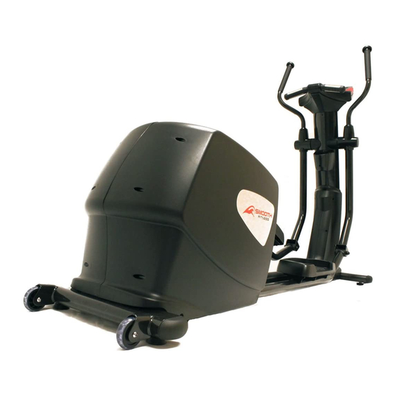
CE-8.0LC
Product May Vary Slightly From Pictures
MADE IN TAIWAN
Exercise can present a health risk. Consult a physician before beginning any exercise program
with this equipment.
If you feel faint or dizzy, immediately discontinue use of this equipment. Serious bodily injury
can occur if this equipment is not assembled and used correctly. Serious bodily injury can also
occur if all instructions are not followed.
Keep children and pets away from equipment when in use. Always make sure all bolts and nuts
are tightened prior to each use. Follow all safety instructions in this manual.
CAUTION: WEIGHT ON THIS PRODUCT SHOULD NOT EXCEED 180KG / 400LBS.
VERSION: II
Advertisement
Table of Contents

Related Manuals for Smooth Fitness CE-8.0LC


Summary of Contents for Smooth Fitness CE-8.0LC
- Page 1 OWNER’S MANUAL CE-8.0LC Product May Vary Slightly From Pictures MADE IN TAIWAN Exercise can present a health risk. Consult a physician before beginning any exercise program with this equipment. If you feel faint or dizzy, immediately discontinue use of this equipment. Serious bodily injury can occur if this equipment is not assembled and used correctly.
-
Page 2: Safety Instructions
SAFETY INSTRUCTIONS WARNING: To reduce the risk of serious injury, read the following Safety Instructions before using the Elliptical Trainer. Read all warnings posted on the Elliptical Trainer. 2. Read this Owner's Manual and follow it carefully before using the Elliptical Trainer. Make sure that it is properly assembled and tightened before use. - Page 3 HARDWEAR IDENTIFICATION CHART This chart is provided to help identify the hardware used in the assembly process. Place the washers, the end of the bolts, or screws on the circles to check for the correct diameter. Use the small scale to check the length of the bolts and screws. NOTE: The length of all bolts and screws except those with flat heads is measured from below the head to the end of the bolt or screw.
- Page 4 “B EFORE EGIN” Thank you for choosing the CE-8.0LC Elliptical. We take Too often, our busy lifestyles limit our time and great pride in producing this quality product and hope it will opportunity to exercise. The equipment provides a provide many hours of quality exercise to make you feel convenient and simple method to begin your assault on better, look better and enjoy life to its fullest.
- Page 5 “A SSEMBLY NSTRUCTIONS” Place all parts from the box in a cleared area and position them on the floor in front of you. Remove all packing materials from your area and place them back into the box. Read each step carefully before beginning. Detailed Lever- drawing 1 Stabilizer Nut (118)
- Page 6 “A SSEMBLY NSTRUCTIONS” NOTE: Please do not fully tighten Bolts (95) until Step. 8 for the easy assembly NOTE: Do not remove the lock nuts during assembly (103) – TEP 4 Upright Sleeve Assembly CAUTION: Be careful not to damage the Middle Connection Wire (109) while assembling Step 4 to 6. Slide the Upright Sleeve (22) onto the Upright Post (4).
- Page 7 “A SSEMBLY NSTRUCTIONS” – TEP 7 Pedal Support Arm & Pivoting Arm Assembly a. Attach the Left Pedal Support Arm (10) onto the Left Pivoting Arm (8) and secure with the 1x Button Head Bolt (M10xp1.5x85mm) (90) and 1 x Nylon lock Nut (M10xp1.5) (104).
- Page 8 “A SSEMBLY NSTRUCTIONS” – TEP 9 Pedal Assembly a. Attach the Left Pedal Assembly (33L) onto the pedal arm plate that is located in the middle of the Left Pedal Support Arm (10) and secure with the 4x Socket Head Bolt (M8xp1.25x10mm) (83).
- Page 9 “A SSEMBLY NSTRUCTIONS” – TEP 10 Console Bracket Assembly CAUTION: Be careful not to damage the Middle Pulse Sensor Wire (112) while assembling STEP 9. Slide the Console Bracket (18) onto the Upright Post (4) as the FIG1 illustration shows on the top right corner.
- Page 10 “A SSEMBLY NSTRUCTIONS” – TEP 13 Wire Assembly a. Connect the Upper Pulse Sensor Wire (111) to the Middle Pulse Sensor Wire (112). b. Connect the Upper Connection Wire (108) to the Middle Connection Wire (109). NOTE: The number of wire pin should be the same for both wires to connect with as the drawing shown on the right.
- Page 11 “A SSEMBLY NSTRUCTIONS” – TEP 16 Upper Handlebar Assembly NOTE: For shipping purpose, the Button Head Bolts (M8xp1.25x16mm)(88) and Lock Washers (M8)(66) are attached on the Left and Right Action Handlebar (6, 7). a. Remove the 8x Button Head Bolts (M8xp1.25x16mm) (88) and 8 x Lock Washers (M8) (66) from the Left and Right Action Handlebar (6, 7).
- Page 12 “O PERATION NSTRUCTIONS” A. POWER SUPPLY The power connects to the front of the Main Frame (1.) Plug the adaptor’s Power Cord (106B) into an 110v electrical outlet. B. CONSOLE ANGLE ADJUSTMENT To get the best viewable angle, press the area A or B to adjust the display up or down. C.
- Page 13 “C ONSOLE NSTRUCTIONS” ake a few minutes to review the console layout. Below is an overview of the console’s features and functions e recommend that you use the console to help vary your workout routine and keep you focused on your progress toward your fitness goals.
- Page 14 “C NSTRUCTIONS – ” ONSOLE ONSOLE UTTONS onsole uttons ST/STOP a. Press to begin your exercise. ST/STOP b. Press to stop and pause all functions during your exercise program. All the data on the display will pause. ST/STOP c. To resume the program, press again to continue until the program has finished.
- Page 15 “C NSTRUCTIONS – ” ONSOLE ONSOLE UTTONS onsole unctions STOP: When “STOP” flashes, this indicates is paused. TIME: Count Up: If a target time is not selected, TIME will count up from 0:00 to maximum 99:59 minutes. Count Down: If a target time is set, (1:00 TO 99:00; 1 MINUTE INCREMENTS), the console will count down from that selected target time to 0:00.
- Page 16 “C ONSOLE NSTRUCTIONS”– ONSOLE UNCTIONS” PULSE: Place both of hands on the Pulse Sensors located on the Handlebar. The pulse will be displayed within several seconds after the heart symbol “ ” is displayed If the hands are not correctly positioned on the sensor, and a few seconds passes without a pulse input, the console will turn off the pulse circuit.
- Page 17 “C NSTRUCTIONS – USER DATA SETTINGS ” ONSOLE “1” User Data Settings: U0~U4 user setup: After the console lights up with a short beep sound, the display will flash “U0”. “U0” is the default user setting value. Once user information has been stored. The default setting value will change “U”...
- Page 18 “C NSTRUCTIONS – USER DATA SETTINGS ” ONSOLE “2” User Data Settings: HEIGHT setting value: ▲(+) ▼(-) a. Use button to select HEIGHT (40~80 inches; 1 inch increments). NOTE: This product is not recommended for use by children b. Press ENTER button to confirm HEIGHT. WEIGHT setting value: ▲(+) ▼(-)
- Page 19 “C NSTRUCTIONS – ONSOLE ANUAL ROGRAM” “1” Manual Program Instruction: a. MANUAL button: Press MANUAL icon button to enter MANUAL PROGRAM. b. Press ENTER button to confirm. ▲(+) ▼(-) button to set the target TIME. NOTE for TIME: Count Up: If a target time was not selected, TIME will count up from 0:00 to maximum 99:59 minutes.
- Page 20 “C NSTRUCTIONS – ONSOLE ANUAL ROGRAM” “1” Manual Program Instruction: ▲(+) ▼(-) button to select the desired value of TARGET PULSE (30 ~ 240 BPM; 1 BPM (BEATS PER MINUTE) . NOTE: During exercise, the console will monitor your pulse and compare the value of your pulse with TARGET PULSE.
- Page 21 “C NSTRUCTIONS – ONSOLE ROGRAM (P1~P12)” “1” P1~P12 Program Instruction: a. PROGRAM button: Press PROGRAM icon button to enter PROGRAM (P1 ~ P12). ▲(+) ▼(-) b. Use button to select the desired PROGRAM (P1 ~ P12). c. Directly press PROGRAM (P1 ~ P12) icon to enter the desired workout program.
- Page 22 “C NSTRUCTIONS – ONSOLE ROGRAM (P1~P12)” “1” P1~P12 Program Instruction: ▲(+) ▼(-) button to set CALORIES. NOTE for CALORIES: Count Up: If target calories were not selected, this measures total calories your body burned during exercise Count Down: If the target calories have been set (10 ~ 990 ; 10 calories increment, the console will count down from the CALORIES Setting selected target calories to 0...
- Page 23 “C NSTRUCTIONS – ONSOLE ROGRAM” WATT Program Instruction: a. WATT button: Press WATT icon button to enter the WATT PROGRAM. ▲(+) ▼(-) button to select the target WATTs (10~350 WATT; 5 WATT INCREMENTS). NOTE for WATT Program: The computer is equipped with LEVEL CONTROL and WATT CONTROL function.
- Page 24 “C NSTRUCTIONS – ONSOLE ROGRAM” WATT Program Instruction: ▲(+) ▼(-) button to set the DISTANCE. NOTE for DISTANCE: Count Up: If a target distance was not selected, this would measure the total distance from 0:00 to 99.99 mile. Count Down: If the target distance is set (0 TO 99.50;...
- Page 25 “C NSTRUCTIONS – ONSOLE ERSONAL ROGRAM” Personal Program Instruction: a. PERSONAL button: Press the PERSONAL icon button to enter PERSONAL PROGRAM. b. Press ENTER button to confirm. c. The PERSONAL PROGRAM allows the user to manually set the RESISTANCE level (from 1 to 24 levels), the console will divide the time into 16 time intervals.
- Page 26 “C NSTRUCTIONS – ONSOLE ERSONAL ROGRAM” Personal Program Instruction: ▲(+) ▼(-) button to select the desired value of DISTANCE. NOTE for DISTANCE: Count Up: If a target distance was not selected, this would measure the total distance from 0:00 to 99.99 mile. ...
- Page 27 “C NSTRUCTIONS – H.R.C. P ONSOLE ROGRAM” “1” H.R.C. Program Instruction: a. H.R.C. button: Press H.R.C. icon button to enter H.R.C. PROGRAM. ▲(+) ▼(-) button to select the H.R.C. program (55%, 75%, 90% of your max. heart rate or Target Heart Rate (30 ~ 240 BPM; 1 BPM (BEATS PER MINUTE).
- Page 28 “C NSTRUCTIONS – H.R.C. P ONSOLE ROGRAM” “1” H.R.C. Program Instruction: ▲(+) ▼(-) button to select the amount of DISTANCE. NOTE for DISTANCE: Count Up: If a target distance was not selected, this would measure the total distance from 0:00 to 99.99 mile. ...
- Page 29 “C NSTRUCTIONS – ONSOLE ANDOM ROGRAM” “1” Random Program Instruction: a. RANDOM button: Press RANDOM icon button to enter RANDOM PROGRAM. NOTE for RANDOM Program: Under RANDOM Program, the console will randomly create workout profiles for the user. The RANDOM Program has more than a hundred of types of random workout profiles.
- Page 30 “C NSTRUCTIONS – ONSOLE ANDOM ROGRAM” “1” Random Program Instruction: ▲(+) ▼(-) button to select the desired value of CALORIES. NOTE for CALORIES: Count Up: If target calories were not selected, this measures total calories your body burned during exercise ...
- Page 31 “C ONDITIONING UIDELINES” How you begin your exercise program depends on your physical condition. If you have been inactive for several years, or are severely overweight, you must slowly and increase your time on the treadmill gradually: a few minutes per workout. Initially, you may be able to exercise only for a few minutes in your target zone, however, your aerobic fitness will improve over the next six to eight weeks.
- Page 32 “W ARM- P AND OOL- OWN” Warm-up The purpose of warming up is to prepare your body for exercise and to minimize injuries. Warm up for two to five minutes before strength-training or aerobic exercising. Perform activities that raise your heart rate and warm the working muscles.
- Page 33 “P RODUCT ARTS RAWING”...
- Page 34 “P IST” Item Name Q'ty Item Name Q'ty CE-8.0-1 Main Frame CE-8.0-36 End Cap (50x100mm) CE-8.0-2 Front Stabilizer CE-8.0-37 Pulley (120mm) CE-8.0-3 Rear Stabilizer CE-8.0-38 Pulley (235mm) CE-8.0-4 Upright Post CE-8.0-39 Magnet CE-8.0-5 Stationary Handlebar CE-8.0-40 Belt (1059mm J6) CE-8.0-6 Left Upper Handlebar CE-8.0-41 Belt (960mm J8) CE-8.0-7 Right Upper Handlebar CE-8.0-42 Square Plug...
- Page 35 IST” Item Name Q'ty Item Name Q'ty CE-8.0-71 Washer (10×23×2.0t) CE-8.0-94 Bolt, Hex Head (M8×p1.25×65mm) CE-8.0-72 Washer (21×30×1.0t) CE-8.0-95 Bolt, Hex Head (M10×p1.5×50mm) Hex Socket Cap Screw CE-8.0-96 Flange Nut (M10×p1.25) CE-8.0-73 (M8×1.25×10mm) CE-8.0-97 Nut (M10×p1.25) CE-8.0-74 Screw (M3×10mm) CE-8.0-98 Nut (M3) CE-8.0-75 Screw (M4×20mm) CE-8.0-99 Nut (M8×p1.25) CE-8.0-76 Screw (M5×18mm)
- Page 36 Hire and reimburse an independent service technician who will come into the home for the repair, In the event that there is not an available certified Smooth Fitness service technician, Smooth will send the part directly to the consumer and will pay $75 US per occurrence for the labor costs of such repair.
Need help?
Do you have a question about the CE-8.0LC and is the answer not in the manual?
Questions and answers