Table of Contents
Advertisement
Quick Links
MIG/ARC WELDER
DUAL MIG WELDER
AssEMbLy AnD OpERAtIOn InstRUCtIOns
Due to continuing improvements, actual product may differ slightly from the product described herein.
Visit our website at: http://www.harborfreight.com
tO pREVEnt sERIOUs InjURy, READ AnD UnDERstAnD
ALL WARnInGs AnD InstRUCtIOns bEfORE UsE.
©
Copyright
2007 by Harbor Freight Tools
manual or any artwork contained herein may be reproduced in any shape or form
without the express written consent of Harbor Freight Tools.
for technical questions or replacement parts, please call 1-800-444-3353.
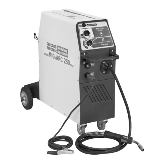
Model 95424 shown.
3491 Mission Oaks Blvd., Camarillo, CA 93011
Model
Model
®
. All rights reserved. No portion of this
95424
95629
®
Advertisement
Table of Contents

Related Manuals for Chicago Electric 95424


Summary of Contents for Chicago Electric 95424
- Page 1 MIG/ARC WELDER Model 95424 DUAL MIG WELDER Model 95629 AssEMbLy AnD OpERAtIOn InstRUCtIOns Model 95424 shown. Due to continuing improvements, actual product may differ slightly from the product described herein. ® 3491 Mission Oaks Blvd., Camarillo, CA 93011 Visit our website at: http://www.harborfreight.com tO pREVEnt sERIOUs InjURy, READ AnD UnDERstAnD ALL WARnInGs AnD InstRUCtIOns bEfORE UsE.
-
Page 2: Table Of Contents
Contents spECIfICAtIOns ................3 GEnERAL sAfEty RULEs ............4 specific safety Rules .................. 6 UnpACKInG ................... 11 AssEMbLy InstRUCtIOns ............11 Attaching the Wheels ................. 11 Installing a Wire spool ................13 Routing the Wire ..................14 Changing Wire settings ................17 Attaching the Ground Cable with Clamp .......... -
Page 3: Specifications
pLEAsE nOtE Models 95424 MIG/ARC WELDER and 95629 DUAL MIG WELDER have identi- cal features except for the ARC option mode available in the 95424 MIG/ARC Welder. The other features are the same, as shown in the Specifications chart below. spECIfICAtIOns Model 95424 MIG/ARC Welder... -
Page 4: General Safety Rules
GEnERAL sAfEty RULEs WARnInG! READ AnD UnDERstAnD ALL InstRUCtIOns failure to follow all instructions listed below may result in electric shock, fire, and/or serious injury. sAVE tHEsE InstRUCtIOns WORK AREA Keep your work area clean and well lit. Cluttered benches and dark areas invite accidents. - Page 5 pERsOnAL sAfEty stay alert. Watch what you are doing, and use common sense when operat- ing a power tool. Do not use a power tool while tired or under the influence of drugs, alcohol, or medication. A moment of inattention while operating power tools may result in serious personal injury.
-
Page 6: Specific Safety Rules
Check for misalignment or binding of moving parts, breakage of parts, and any other condition that may affect the tool’s operation. If damaged, have the tool serviced before using. Many accidents are caused by poorly maintained tools. Use only accessories that are recommended by the manufacturer for your model. - Page 7 prevent eye injury and burns. Wearing and using ANSI-approved personal safety clothing and safety devices reduce the risk for injury. • Wear ANSI-approved safety impact eye goggles underneath welding eye protection featuring at least a Number 10 shade lens rating. •...
- Page 8 material whose contents, when heated, can produce flammable or explosive va- pors. Clean and purge containers before applying heat. Vent closed containers, including castings, before preheating, welding, or cutting. Avoid overexposure to fumes and gases. Always keep your head out of the fumes.
- Page 9 protect yourself from electric shock. Do not use outdoors. Insulate yourself from the workpiece and ground. Use nonflammable, dry insulating material if possible, or use dry rubber mats, dry wood or plywood, or other dry insulating material big enough to cover your full area of contact with the work or ground. Ensure that the unit is placed on a stable location before use.
-
Page 10: Extension Cords
Grounding nOtE: this Welder requires the installation of a 3-prong, 230 VAC, polarized, twistlock power Cord plug (not included). nEMA configuration # L6-40 or equivalent. the plug must be installed by a certified electrician. WARnInG! Improperly connecting the grounding wire can result in risk of electric shock. Check with a qualified electrician if you are in doubt as to whether outlet is prop- erly grounded. -
Page 11: Unpacking
UnpACKInG When unpacking, make sure all parts shown on the parts Lists near the end of this manual are included. If any parts are missing or broken, call Harbor Freight Tools. AssEMbLy InstRUCtIOns WARnInG! Always turn off the Welder and unplug the unit from its electri- cal outlet prior to performing any assembly, maintenance, or service. - Page 12 AssEMbLy InstRUCtIOns (COntInUED) stationary Mobile Install the Back Wheels (37A) at the Axle (36A). Install the Back Wheels (37A) at the Axle (36A). Fix the Back Wheels(37A) with the Fix the Back Wheels (37A) with the Clips (38A). Clips (38A). Arm (5A) Washer and Bolt Set the Axle (36A) with the Back Wheels...
-
Page 13: Installing A Wire Spool
AssEMbLy InstRUCtIOns (COntInUED) InstALLInG A WIRE spOOL TO INSTALL THE WIRE SPOOL Assembling the Wire Spool depends on whether you are using a 7” Spool or an 11” TO INSTALL THE WIRE SPOOL Two variants to expose the Wire Drive Assembly are probable for Spool 200mm (variant A) Spool. -
Page 14: Routing The Wire
AssEMbLy InstRUCtIOns (COntInUED) Insert the Spool onto the Spool′s Holder. Making sure the Spool's Welding Wire Attach a Spool with the help of latch. unwinds from the bottom (clockwise). Screw the Fixing Cover into the Threaded Shaft (11A). ROUtInG tHE WIRE note: When installing wire of different size or composition, you will also need to change wire settings, set gun polarity, and, possibly, install gas cylinder. - Page 15 Loosen, and lower the Handle (4D) on the Wire Drive Assembly. Then, raise the Loosen, and lower the Handle (4D) on the Wire Drive Assembly. Then, raise the Loosen, and lower the Handle (4D) on the Wire Drive Assembly. Then, raise the AssEMbLy InstRUCtIOns (COntInUED) Lever (3D).
- Page 16 AssEMbLy InstRUCtIOns (COntInUED) Lay Torch Cable out in a straight line so Welding Wire moves through it easily. Leave Door (14A) of the Welder open so Wire Feed Assembly can be observed. Remove the Gun Nozzle (1E) and Contact Tip (2E). (see figure E.) WARnInG! ExERCIsE ExtREME CAUtIOn - RIsK Of fIRE AnD/OR ELECtRIC sHOCK! the following steps require powering the Welder.
-
Page 17: Changing Wire Settings
WARNING! Make sure to turn off the Welder and unplug it from its electrical outlet prior to changing wire settings. 1. Lift the Door (14A) of the Welder to expose the Wire Drive Assembly. 2. Loosen, and lower the Handle (4D) on the Wire Drive Assembly. CHAnGInG WIRE sEttInGs 3. -
Page 18: Setting Polarity For Welding Type
sEttInG pOLARIty fOR WELDInG typE WARnInG! Always turn welder off and disconnect it from it’s electrical supply before opening the case or performing any adjustment, including the following pro- cedure. SETTING THE GUN & ELECTRODE POL SETTING THE GUN & ELECTRODE POL set for Electrode positive (DCEp) for gas DCEp DCEp... -
Page 19: Installing A Gas Cylinder
(See Figure G) 4. Remove the protective cap from the cylinder. Stand to the side of the cylinder valve, and open the valve slightly to blow dust and dirt from the valve. Then, close the valve. (See Figure G) 5. Make sure the Flow Adjust on the Pressure Regulator/Flow Meter is turned off. Then, InstALLInG A GAs CyLInDER screw the Pressure Regulator/Flow Meter firmly onto the cylinder valve. -
Page 20: Operating Instructions
OpERAtInG InstRUCtIOns bEfORE yOU bEGIn WELDInG Good welding requires a high degree of skill and experience. You should practice a few sample welds on scrap metal before you begin welding your first project. Ad- ditional practice periods are recommended whenever you weld a different thickness of material, wire, or weld a different type of connection. -
Page 21: Setting Up The Weld
sEttInG Up tHE WELD WARnInG! before welding, make sure to read and understand all safety precautions and warnings discussed on pages 4 through 10. power switch (1C): Always make sure the Power Switch is in its “OFF” posi- tion before plugging the Welder into a 230 volt, grounded, electrical outlet. (see figure j). -
Page 22: Mig Welding Set Up
MIG WELDInG sEt Up If using solid-core wire, connect and secure an Argon/ CO gas hose to the rear of the Welder. (If using flux core wire, protective gas is not required.) OVERLOAD PROTECTOR (2C) POWER SWITCH (1C) WIRE FEED SPEED KNOB (3C) ELECTRODE WELDING... -
Page 23: Mig Weld Settings Chart
MIG WELD sEttInGs CHARt fIGURE j This Chart is intended to show general guidelines for different wire sizes and for different thickness of material. The settings should only be used at the beginning of a weld WELD SETTINGS CHART and must be adjusted after stopping and carefully inspecting the weld. Proper welding takes good technique and practice. -
Page 24: Holding The Welding Torch/Electrode Holder (For All Welding Types)
Arc (stick) Welding set Up (continued, for Model 95424 Only) Turn the Power Switch (1C) to its “Off” position. Clamp the bare end of the selected electrode in the electrode holder. Electrode Penetration Attributes NI-CL Shallow For cast Iron 308L Shallow For stainless steel 6011... -
Page 25: When The Weld Is Completed
If the electrode fuses to the workpiece, quickly twist to release it and lift it slightly farther on your next attempt. The Welding Wire/Electrode should be directed straight into the joint. This gives an angle of 90 degrees (straight up and down) for groove (end to end) welds, and an angle of 45 degrees for fillet (T-shaped) welds. -
Page 26: Inspection, Maintenance, And Cleaning
InspECtIOn, MAIntEnAnCE, AnD CLEAnInG WARnInG! before performing any maintenance on the Welder, unplug the power Cord (1A) from its electrical outlet and allow all components of the Welder to completely cool. Periodically open the Door (14A) from the unit and, using compressed air, blow out all dust and debris from the interior. -
Page 27: Replacing The Welding Torch Liner
REPLACING THE WELDING TORCH LINER REpLACInG tHE WELDInG tORCH LInER (MIG OnLy) Remove NOZZLE, slip type. Remove TIP. 1.Disconnect GUN TERMINAL (11D) & TERMINAL (12D). 2.Untwist NUT (9D). 3.Remove GUN (20A) & CABLES (15A), (18A) & two SEALING WASHERS (8D). Remove LINER. -
Page 28: Parts Lists And Diagrams
pARts LIsts AnD DIAGRAMs pARts LIst A part Description Qty. part Description Qty. Power Cord (8 AWG x 3C: 250V)l Gun (SB 250) Electrode Cable w/ Holder Power Cord Clip (only for 95424 MIG/ARC Welder) Chain Ground Cable w/ Clamp Hose Connector Front Pane;/Base (see Fig. - Page 29 AssEMbLy DIAGRAMs figure L For technical questions, please call 1-800-444-3353; for technical questions, please call 1-800-444-3353; MIG&ARC 250 AMP - SKU 95424 Page 32 SKU 95424, 95629 Page 29 MIG DUAL 250 AMP – SKU Troubleshooting section at end of manual. troubleshooting section at end of manual.
- Page 30 AssEMbLy DIAGRAMs (COntInUED) power block #32A PARTS LISTS & ASSEMBLY DIAGRAMS part Description Qty. part Description Qty. Main Transformer Filter Reactor w/ Thermo Resistor Power Block # 32A Rectifier Auxiliary Transformer Tr2 Part # Description Qty. Part # Description Qty. Main Transformer Tr1 Filter Reactor w/Thermo Resistor Fixing Corner...
- Page 31 AssEMbLy DIAGRAMs (COntInUED) front panel #23A PARTS LISTS & ASSEMBLY DIAGRAMS part Description Qty. part Description Qty. Power Switch Terminal Ground Front Panel # 23A Overload Indicator Front Panel Part # Description Qty. Part # Description Qty. Wire Feed Speed Knob Gun (SB 250) (see Fig.
- Page 32 AssEMbLy DIAGRAMs (COntInUED) Wire Drive Assembly #16A part Description Qty. part Description Qty. PARTS LISTS & ASSEMBLY DIAGRAMS Gear Motor Sealing Washer Wire Drive Assy. # 16A Base Nut (M10) Lever Gun (SB 250) Part # Description Qty. Part # Description Qty.
- Page 33 AssEMbLy DIAGRAMs (COntInUED) Gun (sb 25) #20A part Description Qty. part Description Qty. Nozzle (Slip Type) Nut (M12) Contact Tip Liner PARTS LISTS & ASSEMBLY DIAGRAMS Spring Liner Terminal Head Tube Gun (SB 250) # 20A Switch Trigger Terminal Sealant Trigger Switch Part # Description...
-
Page 34: Mig/Arc Welder (95424) - Electrical Schematic
MIG/ARC WELDER (95424) – ELECtRICAL sCHEMAtIC ELECTRICAL SCHEMATIC MIG/ARC 250 AMP WELDER For technical questions, please call 1-800-444-3353; MIG&ARC 250 AMP - SKU 95424 Page 37 MIG DUAL 250 AMP – SKU Troubleshooting section at end of manual. for technical questions, please call 1-800-444-3353; SKU 95424, 95629 Page 34 troubleshooting section at end of manual. -
Page 35: Mig Dual Welder (95629) - Electrical Schematic
MIG DUAL WELDER (95629) – ELECtRICAL sCHEMAtIC ELECTRICAL SCHEMATIC MIG DUAL 250 AMP WELDER For technical questions, please call 1-800-444-3353; MIG&ARC 250 AMP - SKU 95424 Page 38 MIG DUAL 250 AMP – SKU Troubleshooting section at end of manual. for technical questions, please call 1-800-444-3353;... - Page 36 pOWER CORD, COnnECtIOn bLOCK bC-4 & tRAnsfORMERs COnnECtIOn sCHEMAtIC POWER CORD, CONNECTION BLOCK BC-4 & TRANSFORMERS CONNECTION SCHEMATIC For technical questions, please call 1-800-444-3353; MIG&ARC 250 AMP - SKU 95424 Page 39 MIG DUAL 250 AMP – SKU Troubleshooting section at end of manual. for technical questions, please call 1-800-444-3353;...
-
Page 37: Troubleshooting
tROUbLEsHOOtInG IMpORtAnt! be CERtAIn to shut off the Welder, disconnect it from power, and discharge the torch to ground before adjusting, cleaning, or repairing the unit. Welder does not function when switched on pOssIbLE CAUsEs AnD sOLUtIOns tripped thermal protection device: Shut the welder’s switch to off and allow it to cool for at least 20 minutes. - Page 38 tROUbLEsHOOtInG (continued) IMpORtAnt! be CERtAIn to shut off the Welder, disconnect it from power, and discharge the torch to ground before adjusting, cleaning, or repairing the unit. Wire feed motor runs but wire does not feed (MIG welding only) pOssIbLE CAUsEs AnD sOLUtIOns Insufficient wire feed pressure: Increase wire feed pressure properly - follow instructions on page 14 - 17.
- Page 39 tROUbLEsHOOtInG (continued) IMpORtAnt! be CERtAIn to shut off the Welder, disconnect it from power, and discharge the torch to ground before adjusting, cleaning, or repairing the unit. Wire feeds, but shielding gas does not flow (MIG welding only) pOssIbLE CAUsEs AnD sOLUtIOns Empty Gas Cylinder: Check gas cylinder.
Need help?
Do you have a question about the 95424 and is the answer not in the manual?
Questions and answers