Advertisement
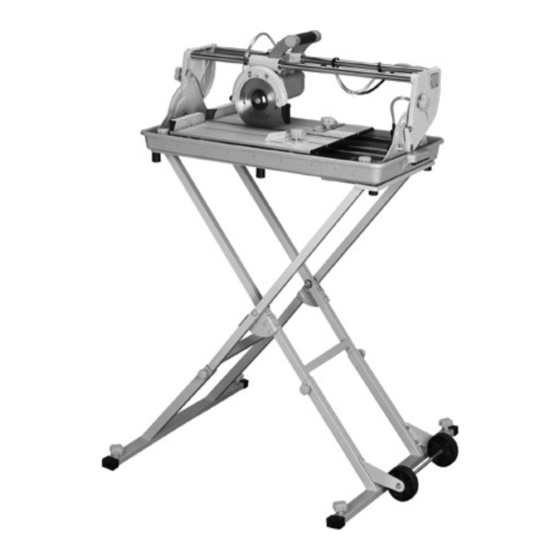
1.5 HP 7" BRIDGE TILE SAW
SET UP AND OPERATING INSTRUCTIONS
Note: Stand (SKU 98328) and Diamond Blade sold separately.
Visit our website at: http://www.harborfreight.com
Read this material before using this product.
Failure to do so can result in serious injury.
SAVE THIS MANUAL.
©
Copyright
2008 by Harbor Freight Tools
contained herein may be reproduced in any shape or form without the express written consent of Harbor
Freight Tools. Diagrams within this manual may not be drawn proportionally. Due to continuing improve-
ments, actual product may differ slightly from the product described herein. Tools required for assembly
and service may not be included.
For technical questions or replacement parts, please call 1-800-444-3353.
Model
98265
®
. All rights reserved. No portion of this manual or any artwork
Manual Revised 10f
Advertisement
Table of Contents

Related Manuals for Chicago Electric 98265


Summary of Contents for Chicago Electric 98265
- Page 1 1.5 HP 7” BRIDGE TILE SAW Model 98265 SET UP AND OPERATING INSTRUCTIONS Note: Stand (SKU 98328) and Diamond Blade sold separately. Visit our website at: http://www.harborfreight.com Read this material before using this product. Failure to do so can result in serious injury. SAVE THIS MANUAL.
-
Page 2: General Tool Safety Warnings
CAUTION, without the SAVE THIS MANUAL safety alert symbol, is Keep this manual for the safety warnings used to address practices not and precautions, assembly, operating, inspec- related to personal injury. tion, maintenance and cleaning procedures. General Tool Safety Warnings Write the product’s serial number in the back of the manual near the assembly diagram (or WARNING Read all safety warnings... - Page 3 14. MAINTAIN TOOLS WITH CARE. Keep RECOMMENDED MINIMUM WIRE tools sharp and clean for best and saf- GAUGE FOR EXTENSION CORDS est performance. Follow instructions for (120 VOLT) lubricating and changing accessories. EXTENSION CORD NAMEPLATE LENGTH AMPERES 15. DISCONNECT TOOLS before servicing; (at full load) 25’...
-
Page 4: With Three Prong Plugs
3-pole receptacles that accept the tool’s GROUNDING INSTRUCTIONS plug. TO PREVENT Repair or replace damaged or worn cord ELECTRIC SHOCK immediately. AND DEATH FROM INCORRECT GROUNDING WIRE CONNECTION READ AND FOLLOW THESE INSTRUCTIONS: Grounding 110-120 V~ Grounded Tools: Tools with Three Prong Plugs In the event of a malfunction or break- 125 V~ 3-Prong Plug and Outlet down, grounding provides a path of least... - Page 5 Do not perform any operation freehand. closing on the saw blade. Spreaders, except riving knives, must be aligned Never reach around or over saw blade. to the blade after blade adjustment to prevent binding. Make sure the workpiece is supported at all times while sawing.
- Page 6 check that the saw teeth are not en- gaged into the workpiece before turn- ing on the saw. • Push the wood stock past the blade prior to release. 11. Check guards for proper operation with saw disconnected from power before each use.
- Page 7 Essential Straight Push-stick Features and Functions Note: Straight style (traditional) stick shown. A dif- ferent stick design may be used if it properly Handle Notch protects against all hazards. • Must be far Diagram not to scale. enough down • Push sticks must be made from sturdy, defect-free, the stick to allow plywood or normal wood to prevent unexpected a comfortable and...
- Page 8 POSITION OF TILE SAW heat and sharp edges. Always discon- nect the extension cord from the recep- tacle before disconnecting the product from the extension cord. WARNING – To reduce the risk of elec- trocution, keep all connections dry and off the ground.
- Page 9 12. Industrial applications must follow OSHA depending on how often you do this type guidelines. of work. To reduce your exposure to these chemicals: work in a well ventilat- 13. Maintain labels and nameplates on the ed area, and work with approved safety tool.
- Page 10 fingers), seek medical advice as soon as possible. Do not smoke during use. Nicotine re- duces the blood supply to the hands and fingers, increasing the risk of vibration- related injury. Wear suitable gloves to reduce the vibra- tion effects on the user. Use tools with the lowest vibration when there is a choice between different pro- cesses.
-
Page 11: List Of Contents
SPECIFICATIONS TO PREVENT SERIOUS INJURY FROM ACCIDENTAL Maximum Blade Diameter 7" OPERATION: Arbor Hole 5/8" Turn the Power Switch of the tool 1-1/8" @ 90° Maximum Cutting Capacity to its “OFF” position and unplug 3/4" @ 45° the tool from its electrical outlet Tilting Head 45°... -
Page 12: Operating Instructions
Mounting This tool can be placed on a table or other stable surface. The ideal method would be to mount the tile saw on the stand made for it, SKU 98328 (not in- cluded, sold separately). OPERATING INSTRUCTIONS Read the ENTIRE IMPORTANT SAFETY INFORMATION section at the beginning of this manual including all text under... -
Page 13: General Operating Instructions
General Operating Instructions Power Switch Knob Sliding Bar Support Bevel Scale Reset Button Fig. 4 Fig. 3 Beveled cuts can also be When making a flat cut, slide the accomplished by loosening the Knobs piece to be cut up against the two (D27) on either side of the saw. - Page 14 Maintenance, And Cleaning” section MAINTENANCE AND of this manual. Use of unauthorized SERVICING parts or failure to follow maintenance instructions may create a risk of electric Procedures not specifically explained shock or injury. in this manual must be performed only by a qualified technician. WARNING! If the supply cord of this power tool is damaged, it must be TO PREVENT SERIOUS...
-
Page 15: Troubleshooting
Remove the blade and replace with a move the plug and drain the water and new one. Make sure the arrow on the silt accumulated by the cutting operation. blade matches the direction of the arrow Use more water to clean out the residual embossed on the blade cover. - Page 16 PARTS LIST AND ASSEMBLY DIAGRAM A (MOTOR) Part Description Part Description Part Description A01 Screw (M5x12) A19 Switch Body A36 Shaft A02 Hose Connect A20 Thermal Protector A37 Key A03 Water Tubing A21 Press Plate A38 Gear A04 Screw (M5x10) A22 Joint A39 Screw (ST4x30) A05 Inner Flange...
- Page 17 PARTS LIST AND ASSEMBLY DIAGRAM B (HANGER) Part Description Qty. Screw (M4x6) Screw (M4x20) Hex Nut (M4) Linear Bushing Felt Bushing Seal Bearing Hex Bolt (M6x20) Holder Knob Flat Washer Screw (M5x12) Handle End Cap REV 10b SKU 98265 For technical questions, please call 1-800-444-3353. Page 17...
- Page 18 PARTS LIST AND ASSEMBLY DIAGRAM C (SUPPORT) Part Description Qty. Part Description Qty. Steel Support B Sliding Bar Connection Shaft Tubing Holder Set Screw (M4x15) Clip Flat Washer Wrench Knob Wrench Holder Socket Wrench Pointer Spring Washer Sliding Bar Support Flat Washer Bevel Scale Wrench Holder...
- Page 19 PARTS LIST AND ASSEMBLY DIAGRAM D (WORK TABLE) Part Description Qty. Part Description Qty. Hex Nut (M6) Right Worktable Spring Washer Left Worktable Flat Washer Miter Gauge Stainless Steel Frame Rivet Hex Bolt (M6x30) Knob Table End Guide Right Fence Cover 1 Knob Scale Clamp Plate...
- Page 20 PARTS LIST AND ASSEMBLY DIAGRAM E (WATER TRAY) Part Description Qty. Water Tray O-Ring Drain Plug Rubber Cap Flat Washer Set Screw Rubber Feet Carrying Handle Grip REV 10b Page 20 For technical questions, please call 1-800-444-3353. SKU 98265...
-
Page 21: Limited 90 Day Warranty
LIMITED 90 DAY WARRANTY Harbor Freight Tools Co. makes every effort to assure that its products meet high quality and durability standards, and warrants to the original purchaser that this product is free from defects in materials and workmanship for the period of 90 days from the date of purchase. This warranty does not apply to damage due directly or indirectly, to misuse, abuse, negligence or accidents, repairs or alterations outside our facilities, criminal activity, improper installa- tion, normal wear and tear, or to lack of maintenance.
Need help?
Do you have a question about the 98265 and is the answer not in the manual?
Questions and answers
replacement parts for 98265 A-16,B-****D-8,D-9,D12,D-13
The replacement parts for the Chicago Electric model 98265 listed in the manual include:
- B01 Screw (M4x6) – 3
- B02 Screw (M4x20) – 1
- B03 Hex Nut (M4) – 1
- B04 Linear Bushing – 2
- B05 Felt Bushing – 4
- B06 Seal – 4
- B07 Bearing – 4
- B08 Hex Bolt (M6x20) – 4
- B09 Holder – 1
- B10 Knob – 1
- B11 Flat Washer – 2
- B12 Screw (M5x12) – 2
- B13 Handle – 1
- B14 End Cap – 2
Some parts are listed for illustration purposes only and may not be available individually as replacement parts.
This answer is automatically generated
replacement parts for 98265 A-16,B-****-8,D-9,D12,D-13