
Related Manuals for Newcon Optik LRB 6000CI


Summary of Contents for Newcon Optik LRB 6000CI
- Page 1 Operation Manual LRB 6000CI LASER RANGE FINDER BINOCULARS 105 Sparks Ave., Toronto, ON M2H 2S5, Canada...
-
Page 3: Important Information
IMPORTANT INFORMATION Read prior to activation You have just purchased a sophisticated electro-optical device that emits invisible laser radiation. To operate it properly, please read this manual carefully. NEVER direct laser beam at the eyes of people or animals ... - Page 4 Caution - use of optical instruments such as binoculars, loupes, mirrors, lenses, etc. with this product increases eye hazard Note: Avoid eye exposure to direct laser beam or its close reflection Prevent bright light from focusing through the eyepieces ...
-
Page 5: Table Of Contents
TABLE OF CONTENTS BRIEF DESCRIPTION..........2 DEVICE APPEARANCE ..........4 DELIVERY SET............7 SPECIFICATIONS ............8 OPERATION INSTRUCTIONS........10 Installing the battery............. 10 Using the Device ............11 Factors affecting measuring distance ......12 Target selection logic ........... 13 Operation and service modes ........14 Accuracy correction ............. -
Page 6: Brief Description
CAREFULLY READ ALL THE INSTRUCTIONS PRIOR TO USE! FAILURE TO OBEY THE INSTRUCTIONS WILL VOID THE WARRANTY AND MAY CAUSE INJURY! 1. BRIEF DESCRIPTION LRB 6000CI Laser Rangefinder Binoculars (System) is an advanced laser range finder system that enables instant distance, speed, vertical and horizontal angular measurements. - Page 7 Key Features of the LRB 6000CI Laser Rangefinder Binoculars Modern digital circuitry allows targeting through most types of glass First, last or the most reflective target acquisition Meters/Yards/Mils/Degrees/KMH/MPH display Last 10 measurements recall Selectable reticle shape (+ or ) ...
-
Page 8: Device Appearance
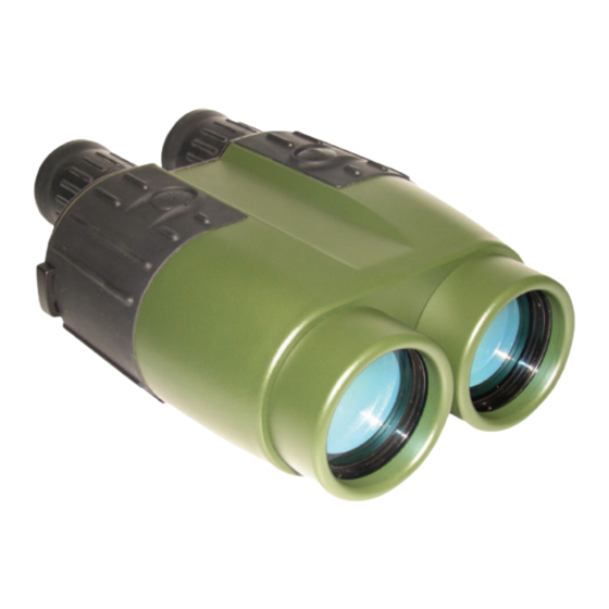
2. DEVICE APPEARANCE Fig. 1. Front view 1 – Eyepieces 2 – Objective / receiving lens 3 – Objective / emitting 4 – Dioptric adjustment rings lens 5 – Mode button 6 – Action button 7 – Body of the device 8 –... - Page 9 Fig. 2 Rear view 1 – Eyepiece 9 – Interpupillary distance adjustment lever 10 – Model Identification label 11 – Identification and certification label (at the bottom):...
- Page 10 Fig. 3 Display 2 – Reticle (either -¦- or ) 1 – Low battery indicator 3 – Units of measurement 4 – Measurement result 5 – Gating indicator 6 – Laser active indicator 7 – Ready mode indicator 8 – Setup mode indicator...
-
Page 11: Delivery Set
3. DELIVERY SET Standard delivery set for LRB 6000CI includes: LRB 6000CI 1 pc. Carrying case 1 pc. Neck strap 1 pc. User’s manual 1 pc. Warranty card 1 pc. Cleaning cloth 1 pc. Computer cable 1 pc. CD with communication software 1 pc. -
Page 12: Specifications
4. SPECIFICATIONS Optics Magnification Objective lens diameter 50 mm Exit pupil diameter 7.1 mm Field of view 5 Type of coating Fully multi-coated optics Interpupillary distance 58-72 mm Dioptre adjustment range ±4 Range Finder Laser Class 1, eye safe, 905 nm Measuring range 1 –... - Page 13 Compass Measured azimuth range 6400 mils /360 Accuracy ±1 Inclinometer Measured elevation range ±60 Accuracy ±1 Height measuring Yes (Meters or Yards) Power Battery 9V Lithium (non-magnetic) Battery capacity Min 5,000 measurements (Scanning regime) 'Low Battery' indicator Environmental Operational temperature range -25…+50 (-13…+122 Storage temperature range...
-
Page 14: Operation Instructions
5. OPERATION INSTRUCTIONS Installing the battery Open the battery compartment using a suitable tool, or a coin. Insert a 9V Lithium non-magnetic battery provided with your device Connect the battery to the battery snap Refit the battery compartment and tighten the screw. If the battery compartment cover does not close tightly and evenly, check that the battery snap wires are neatly packed inside the battery compartment and the cover is... -
Page 15: Using The Device
Using the Device The LRB 6000CI operational procedures are design to allow the user to use most applicable options in the fastest time possible. To activate it, press and hold Action button (6, Fig.1) for one second. At start the unit comes into Ready to Measure mode indicated by the word ‘READY’... -
Page 16: Factors Affecting Measuring Distance
Factors affecting measuring distance Though maximum measurement distance depends on target reflectivity, weather conditions and other conditions, for most targets the unit will provide accurate ranging for up to 4,000 meters. Under good conditions a large size target can be measured up to 6,500 meters. Target reflectivity depends on its color, surface finish, size, shape, position in relation to the laser beam, etc. -
Page 17: Target Selection Logic
Target selection logic On its way towards the target the laser beam may be reflected from various objects, thus decreasing ranging accuracy. The smaller, the farther, and the less reflective is the target – the higher is the possibility of obtaining an incorrect measurement. -
Page 18: Operation And Service Modes
Scanning regime the unit repeatedly measures and displays results every second while A button is pressed. To activate Scanning regime press and hold Action button in Ready mode. The unit will work in Scanning regime while Action button is pressed. Scanning or Individual Measurement regimes are available for any selected mode of measurement. - Page 19 Std – allows the user to select single action measurements: Distance only (d) Compass Only (C) Elevation Only (E) Speed Only (S) Height Only (H) Speed + Distance (Sd) Distance +Compass + Elevation (dCE) Unit – allows the user to select units of desired measurements, Distance from M to Y Compass &...
-
Page 20: Accuracy Correction
AUtO – Last Target Measurement* PLGr – Communication to PLGR GPS* PC – Communication to PC* Reticule – Change reticule from + (cross) to (rectangle) CAL – Compass calibration ▪ CALc – compass calibration (CI model only) ▪ Corr – accuracy correction of active parameters *not shown in the menu if currently selected Accuracy correction... - Page 21 Active mode of Correction measurement Condition parameter (Std) Install unit at 1 meter S, Sd, d Distance from flat target Put unit in a level plane Azimuth and C, E and aim it to the North elevation direction Install unit at 1 meter Distance, from flat target azimuth and...
-
Page 22: Compass Calibration
Compass calibration If the System was exposed to a strong magnetic field or was not in use for a long time, the compass accuracy may diminish. To return the compass into working condition: Select CALc from CAL menu Keeping the unit horizontally, perform one full rotation around vertical axis within half a minute and then one full rotation around vertical axis with device... -
Page 23: Gating Mode
Gating mode In this mode gating function is activated: here user can set the minimal distance to the target, any object closer than the gating distance will be ignored. To select Gating Mode: Select GAtE from main menu Minimal gating distance of 0 meters (display: 000 m) will be initially set, further pressing M button will increase gating distance by 100 m up to 3,900 m. -
Page 24: Data Recall Mode
Data Recall mode In Data Recall mode results of the last 10 measurements can be displayed. Measurement results are saved in on-board memory in sets depending on the parameters set for measuring, for instance, if only distance is measured - the set will consist of one number, if distance and azimuth are measured –... -
Page 25: Computer Interconnectivity
Computer interconnectivity The unit supports RS-232 interface. Physical connection is performed through connector with threaded coupling mechanism, designed for the heavy-duty outdoor applications. Note: Do not apply excessive force when disconnecting cable. Damage to cable or connector resulting from improper treatment is not covered by warranty. To attach the cable to the rangefinder match the key on the plug (1, Fig. -
Page 26: Gps Interconnectivity
GPS interconnectivity LRB 6000CI can transmit the acquired data to a GPS receiver using DB15 connector and PLGR/DAGR protocol. An optional cable is required. To work with GPS, perform the following steps: Switch the rangefinder to PLGr mode; Choose dFLt measuring mode;... -
Page 27: Best Measuring Technique
6. BEST MEASURING TECHNIQUE Laser range finder measures distance by catching laser beam reflected from the target. Everything that improves reflection increases the measurement reliability and maximum range. 1. Use tripod when ranging remote targets. The longer is the distance, the greater is the beam shift due to hand tremor. - Page 28 reflections from all objects closer than the gating distance will be ignored. This is especially effective when ranging in unfavourable atmospheric conditions, that is, in the rain, fog, haze or in the bright sun. Gating provides better results than the “last”...
-
Page 29: Storage And Maintenance
7. STORAGE AND MAINTENANCE The unit is a sophisticated precision optical instrument equipped with laser and electronics. Therefore, it should be handled with due care. Keep away from direct sunlight. Avoid impacts, jolts, dust, moisture, and sharp changes of temperature. ... -
Page 30: Troubleshooting
8. TROUBLESHOOTING Ranging does not work. The display is transparent. Check the charge of the battery. Replace it if it is weak. Ranging does not work. The display indicates results of the last measurement. Wait for 8 seconds until the display becomes transparent, and press the Action button again. -
Page 31: Warranty
Postage, insurance, and shipping costs incurred while presenting your NEWCON product for warranty service are your responsibility. If shipping from North America please include a cheque or money order payable to NEWCON OPTIK for the amount of US$15.00 to cover handling and return shipping. -
Page 32: Customer Support
CUSTOMER SUPPORT Should you experience any difficulties with your NEWCON OPTIK product, consult the enclosed manual. If the problem remains unresolved, contact our customer support department at (416) 663-6963 or toll free at 1- 877-368-6666. Our operating hours are 9am-5pm, Monday - Friday, Eastern Standard Time. -
Page 33: Quality Certificate
QUALITY CERTIFICATE Serial number _____________________________ The unit indicated above has passed the quality inspection. Production date Quality Inspector Purchase date... - Page 36 NEWCON OPTIK Printed in Canada...
Need help?
Do you have a question about the LRB 6000CI and is the answer not in the manual?
Questions and answers