
Related Manuals for Newcon Optik LRB 4000CI


Summary of Contents for Newcon Optik LRB 4000CI
- Page 1 Operation Manual LRB 4000CI LASER RANGE FINDER BINOCULARS NSN: 1240-20-001-9644 105 Sparks Ave., Toronto, ON M2H 2S5, Canada...
-
Page 2: Important Information
IMPORTANT INFORMATION READ PRIOR TO ACTIVATION You have just purchased a sophisticated electro-optical device that emits invisible laser radiation. To operate it properly, please read this manual carefully. NEVER direct laser beam at the eyes of people or animals ... - Page 3 ALWAYS keep the unit out of children’s reach ALWAYS remove the battery when the device is not in use for a long period ALWAYS store in a dry place CAUTION - use of controls or adjustments, or performance of procedures other than those specified herein may result in hazardous radiation exposure ...
-
Page 4: Table Of Contents
TABLE OF CONTENTS 1. BRIEF DESCRIPTION ........4 2. DEVICE APPEARANCE ......... 6 3. DELIVERY SET ..........9 4. SPECIFICATIONS ......... 10 5. OPERATION INSTRUCTIONS ....13 5.1 Installing the battery......13 5.2 Using the Device ........14 5.3 Factors affecting measuring distance ..15 5.4 ... -
Page 5: Brief Description
1. BRIEF DESCRIPTION LRB 4000CI Laser Rangefinder Binoculars (System) is an advanced laser range finder system that enables instant distance, speed, vertical and horizontal angular measurements. An outstanding optics provides a sharp, clear image under any observation conditions. The unit utilises time-of-flight method of distance and speed measurement. - Page 6 Key Features of the LRB 4000CI Laser Rangefinder Binoculars Modern digital circuitry allows targeting through most types of glass First, last or the most reflective target acquisition Meters/Yards/Mils/Degrees/KMH/MPH display Last 10 measurements recall Selectable reticle shape (+ or ) ...
-
Page 7: Device Appearance
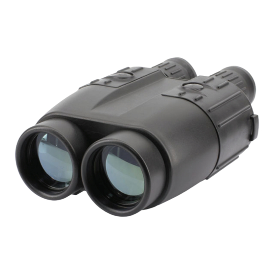
2. DEVICE APPEARANCE Fig. 1. Front view 1 – Eyepieces 2 – Objective / receiving lens 3 – Objective / emitting lens 4 – Dioptric adjustment rings 5 – Mode button 6 – Action button 7 – Body of the device 8 –... - Page 8 Fig. 2 Rear view 1 – Eyepiece 9 – Interpupillary distance adjustment lever 10 – Model Identification label 11 – Identification and certification label (on the bottom) Fig. 3 Label...
- Page 9 Fig. 4 Display 1 – Low battery indicator 2 – Reticle (either -¦- or ) 3 – Units of measurement 4 – Measurement result 5 – Gating indicator 6 – Laser active indicator 7 – Ready mode indicator 8 – Setup mode indicator...
-
Page 10: Delivery Set
3. DELIVERY SET LRB 4000CI 1 pc. Carrying case 1 pc. Neck strap 1 pc. User’s manual 1 pc. Warranty card 1 pc. Computer cable 1 pc. CD with communication software 1 pc. Hard case 1 pc. 9V non-magnetic Lithium battery 1 pc. -
Page 11: Specifications
4. SPECIFICATIONS Optics Magnification Objective lens diameter 50 mm Exit pupil diameter 7.1 mm Field of view 5 Type of coating Fully multi-coated optics Interpupillary distance 58-72 mm Dioptre adjustment range ±4 Range Finder Laser Class 1, eye safe, 905 nm Measuring range 10 –... - Page 12 Speed Detection Measured speed range 5-400 km/h or 3-250 mph 2 km/h or mph Accuracy Compass Measured azimuth range 6400 mils /360 Accuracy ±1 Inclinometer Measured elevation range ±60 Accuracy ±1 Height measuring Yes (Meters or Yards) Power Battery 9V Lithium (non-magnetic) Battery capacity Min 5,000 measurements...
- Page 13 Environmental Operational temperature range -25°…+50°C (-13°…+122°F) Storage temperature range -45°…+65°C (-49°…+149°F) Mechanics Tripod thread ¼” x 20 TPI Weight without battery 1.3kg Weight with hard case 3.5 kg Dimensions 210x150x80 mm...
-
Page 14: Operation Instructions
NOTE: Battery in metal casing will diminish compass accuracy. Non-magnetic batteries should be used for the utmost compass performance. LRB 4000CI is equipped with battery monitoring sensor. If display shows “LOW BATTERY” warning when battery voltage falls below 6.5V this indicates that the battery is used up. -
Page 15: Using The Device
5.2 Using the Device The LRB 4000CI operational procedures are design to allow the user to use most applicable options in the fastest time possible. To activate it, press and hold Action button (6, Fig.1) for one second. At start the unit comes into Ready to Measure mode indicated by the word ‘READY’... -
Page 16: Factors Affecting Measuring Distance
5.3 Factors affecting measuring distance Though maximum measurement distance depends on target reflectivity, weather conditions and other conditions, for most targets the unit will provide accurate ranging for up to 3,000 meters. Under good conditions a large size target can be measured up to 4,000 meters. Target reflectivity depends on its color, surface finish, size, shape, position in relation to the laser beam, etc. -
Page 17: Target Selection Logic
5.4 Target selection logic On its way towards the target the laser beam may be reflected from various objects, thus decreasing ranging accuracy. The smaller, the farther, and the less reflective is the target – the higher is the possibility of obtaining an incorrect measurement. - Page 18 Scanning regime the unit repeatedly measures and displays results every second while A button is pressed. To activate Scanning regime press and hold Action button in Ready mode. The unit will work in Scanning regime while Action button is pressed. Scanning or Individual Measurement regimes are available for any selected mode of measurement.
-
Page 19: Operation And Service Modes
5.5 Operation and service modes Pressing Mode button (5, Fig.1) in Ready mode switches the unit between modes of operation, to activate any desired mode from the menu you must confirm your selection by pressing Action button (6, Fig.1). The unit has the following modes of operation: ... - Page 20 Compass & Elevation from Mils to Degrees Speed from KMH to MPH* *note this option is only available if Std Speed is selected rEc – allows data recall of the last 10 measurement results, CLr – Clears all Measurement ...
-
Page 21: Compass Calibration
5.6 Compass calibration Full calibration process consists of three procedures, which shall be conducted in the following sequence: Elevation correction Hard calibration Soft Calibration However all three procedures shall be done only at initial installation and integration of the device, or if some large hardware elements permanently attached to the device were changed. - Page 22 error for all future measurements, this error will be proportional to the Hard calibration Note: during all calibration procedures, always put as far as possible all magnetic/metal parts and devices that generate electromagnetic interference (example – Cellphone) from the measurement area,...
- Page 23 unless these parts or devices will be permanently used in conjunction with the LRF device. - Turn on the LRF. - In the LRF menu select «SET», then «CAL». Press ACTION. - When the text «CALc» is shown, set the LRF horizontally on a flat surface, where the LRF will be rotated around vertical axis.
- Page 24 - Press ACTION. - Start rotating the LRF module to perform on or two full rotations duration 1 min. The display will be blinking «CAL». When display switches to «CALS», it means that calibration is finished. - Press MODE button to exit the calibration mode. Soft calibration...
- Page 25 Prior to conducting the procedure determine accurate direction to North, West, South and East, accuracy of these references will define accuracy of the compass calibration. - Turn on the LRF. - In the LRF menu select «SET», then «CAL». Press ACTION.
-
Page 26: Distance Accuracy Correction
5.7 Distance accuracy correction If the System produces any measurement errors that lie beyond unit specification, it may be an indication that unit requires calibration similar to one conducted at production level. To do accuracy correction, please select Corr from CAL menu. Perform correction according to required measurement parameters by pressing Action button, see table below: Active mode of... -
Page 27: Setting Interface Format
2 – Target should not have high-reflective surface (white color is not considered high reflective in this case). 3 – If device detects measurement result more than elevation correction was not performed. 5.8 Setting interface format In this mode data communication standard is set. The unit can output measurement data via RS-232 port in either PC format (description of the proprietary format can be obtained from Newcon upon a request) or in the format... -
Page 28: Data Recall Mode
Select GAtE from main menu Minimal gating distance of 0 meters (display: 000 m) will be initially set, further pressing M button will increase gating distance by 100 m up to 3,900 m. When the desired distance is reached – select it by pressing Action button. - Page 29 of one number, if distance and speed are measured – the set will consist of two numbers. To enter Data Recall mode select rEc from the main menu. First measurement set number (display name: rEc 1) will start flashing. Pressing M button moves the unit along the list of measurement set numbers and measurement results: rEc 1, distance 1, azimuth 1, elevation 1, rEc 2, distance 2, azimuth 2, elevation 1,...
-
Page 30: Computer Interconnectivity
5.11 Computer interconnectivity The unit supports RS-232 interface. The data is transmitted as hex string code with fixed baud rate of 38400 bit/sec, 8 bits, one stop bit, and no parity. Physical connection is performed through circular connector designed for the heavy-duty outdoor applications, the connector is located on the bottom of the device. -
Page 31: Gps Interconnectivity
(2, Fig. 4A) and detach the plug. 5.12 GPS interconnectivity LRB 4000CI can transmit the acquired data to a GPS receiver using DB15 connector and PLGR/DAGR protocol. An optional cable is required. - Page 32 Connect the rangefinder and GPS unit with the cable. For each measurement GPS will display the absolute coordinates of your target. NOTE: If the rangefinder is not set initially to dFLt mode, the GPS will not operate properly. NOTE: GPS unit automatically adjusts coordinates to reflect actual magnetic declination.
-
Page 33: Best Measuring Technique
6. BEST MEASURING TECHNIQUE Laser range finder measures distance by catching laser beam reflected from the target. Everything that improves reflection increases the measurement reliability and maximum range. 1. Use tripod when ranging remote targets. The longer is the distance, the greater is the beam shift due to hand tremor. - Page 34 4. Another way to improve reliability of measurement is to use gating mechanism. If gating is active reflections from all objects closer than the gating distance will be ignored. This is especially effective when ranging in unfavourable atmospheric conditions, that is, in the rain, fog, haze or in the bright sun.
-
Page 35: Storage And Maintenance
7. STORAGE AND MAINTENANCE The unit is a sophisticated precision optical instrument equipped with laser and electronics. Therefore, it should be handled with due care. Keep away from direct sunlight. Avoid impacts, jolts, dust, moisture, and sharp changes of temperature. ... -
Page 36: Troubleshooting
8. TROUBLESHOOTING Ranging does not work. The display is transparent. Check the charge of the battery. Replace it if it is weak. Ranging does not work. The display indicates results of the last measurement. Wait for 16 seconds until the display becomes transparent, and press the Action button again. -
Page 37: Warranty
Postage, insurance, and shipping costs incurred while presenting your NEWCON product for warranty service are your responsibility. If shipping from North America please include a cheque or money order payable to NEWCON OPTIK for the amount of US$15.00 to cover handling and return shipping. -
Page 38: Customer Support
CUSTOMER SUPPORT Should you experience any difficulties with your NEWCON OPTIK product, consult the enclosed manual. If the problem remains unresolved, contact our customer support department at (416) 663-6963 or toll free at 1- 877-368-6666. Our operating hours are 9am-5pm, Monday - Friday, Eastern Standard Time. -
Page 39: Quality Certificate
QUALITY CERTIFICATE Serial number __________________________________ The unit indicated above has passed the quality inspection. Production date_________________________________ Quality Inspector________________________________ Purchase date ___________________________... - Page 40 NEWCON OPTIK Printed in Canada...
Need help?
Do you have a question about the LRB 4000CI and is the answer not in the manual?
Questions and answers