
Related Manuals for Newcon Optik LRB 4000CI


Summary of Contents for Newcon Optik LRB 4000CI
- Page 1 Operation Manual LRB 4000CI LASER RANGE FINDER BINOCULARS NSN: 1240-20-001-9644 105 Sparks Ave., Toronto, ON M2H 2S5, Canada...
-
Page 3: Important Information
IMPORTANT INFORMATION Read prior to activation You have just purchased a sophisticated electro-optical device that emits invisible laser radiation. To operate it properly, please read this manual carefully. • NEVER direct laser beam at the eyes of people or animals •... -
Page 4: Table Of Contents
TABLE OF CONTENTS 1. BRIEF DESCRIPTION..........2 2. DEVICE APPEARANCE ........3 3. DELIVERY SET............4 4. SPECIFICATIONS ..........5 5. OPERATION INSTRUCTIONS ......6 5.1. Installing the battery........6 5.2. Measurement procedure ......... 7 5.3. Maximum distance ......... 7 5.4. -
Page 5: Brief Description
FAILURE TO OBEY THE INSTRUCTIONS WILL VOID THE WARRANTY AND MAY CAUSE INJURY! 1. BRIEF DESCRIPTION LRB 4000CI Laser Rangefinder Binoculars (System) is an advanced laser range finder system that enables instant distance, speed, vertical and horizontal angular measurements. An outstanding optics provides a sharp, clear image under any observation conditions. -
Page 6: Device Appearance
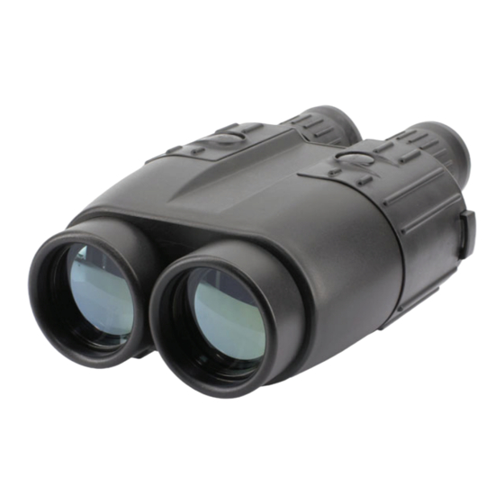
2. DEVICE APPEARANCE Fig. 1. Front view 1 – Eyepieces 2 – Objective / receiving lens 3 – Objective / emitting lens 4 – Dioptric adjustment rings 5 – Mode button 6 – Action button 7 – Body of the device 8 –... -
Page 7: Delivery Set
5 – Target quality indicator 6 – Laser active indicator 7 – Gating indicator 8 – Setup mode indicator 9 – Ready mode indicator 3. DELIVERY SET Standard delivery set for LRB 4000CI includes: LRB 4000CI 1 pc. Carrying case 1 pc. Neck strap 1 pc. -
Page 8: Specifications
Optional items Remote control module GPS cable Exact delivery set depends on details of a contract or purchase order. 4. SPECIFICATIONS Optics Magnification Objective lens diameter 50 mm Exit pupil diameter 7.1 mm Field of view 5° Type of coating Fully multi-coated optics Interpupillary distance 58-72 mm... -
Page 9: Operation Instructions
Inclinometer Measured elevation range ±60° Accuracy ±1° Height measuring Present Power Battery 9V Lithium (non-magnetic) Battery capacity Min 5,000 measurements (Scanning regime) 'Low Battery' indicator Environmental Operational temperature range -25…+50 C (-13…+122 Storage temperature range -45…+65 C (-49…+149 Mechanics Tripod thread ¼”... -
Page 10: Measurement Procedure
Note: Battery in metal casing will diminish compass accuracy. Non- magnetic batteries should be used for the utmost compass performance. The unit is fully operational when battery voltage is higher than 6.3V. A ‘LOW BATTERY’ warning is displayed when battery voltage falls below 6.5V. -
Page 11: Target Selection Logic
While the unit will measure through many glass types, measuring through glass may reduce accuracy. Natural hand tremor decreases the accuracy of long distance ranging. Using of a tripod is highly recommended. Target selection logic On its way towards the target the laser beam may be reflected from various objects, thus decreasing ranging accuracy. -
Page 12: Mode Switching And Tuning
(Quick link to Standard1 and Standard2 sets of measurement parameters appears in mode selection menu for convenience and does not constitute a separate mode) Setup – to modify the Ready to Measure mode parameters, Gating – to set a minimum distance of measurement Data Recall –... -
Page 13: Setup Mode
COdE Setup mode (display name: Gating selection mode (display name: Data Recall mode (display name: Memory Clearance mode (display name: -PC- PLGr or Interface selection mode (display name: Flashing display name indicates the mode which can be selected by pressing A button (4). Setup, Gating selection, Data Recall and Interface selection modes have submenus, so when A button is pressed to select these modes the unit automatically enters the corresponding submenu. - Page 14 Mode - ◦ Mils -¦- Auto ‘◦ ‘ ‘ Deg Deg -¦- Auto -¦- -¦- Last First Auto NC km/h Display test Compass calibration Gating Entrance into gating mode Data Recall Recalls last 10 measurement sets Data Clearance Clears all recorded data -PC- Interface...
-
Page 15: Compass Calibration
Empty field means the parameter is not measured in this mode, NC means ‘no change’ to the measurement parameter setting To leave the Setup mode without changing measurement parameters press and hold M button for two seconds. This works like computer Esc key. -
Page 16: Gating Mode
Gating mode In this mode gating function is activated: here user can set the minimal distance to the target, any object closer than the gating distance will be ignored. To enter into gating mode press A button when is displayed. Minimal gating distance of 100 m will be initially set, further pressing M button will increase gating distance by 100 m up to 7,000 m. -
Page 17: Display Test Mode
Pressing A button at any moment within the list of recalled results (or pressing M button at the end of the list) brings the unit to Ready to Measure mode. Choosing in Setup mode will erase all measurement data. Display test mode Entering Code 16 will cause all display segments and indicators to flash for 8 seconds. -
Page 18: Gps Interconnectivity
This connector is IP67 graded. GPS interconnectivity LRB 4000CI can transmit the acquired data to a GPS receiver using DB15 connector and PLGR/DAGR protocol. An optional cable is required. To work with GPS, perform the following steps: Switch the rangefinder to PLGr mode;... -
Page 19: Remote Control Module
users planning to work with GPS only. The short mode switching scheme does not transmit data in PC software format. The short mode switching scheme menu comprises only 4 modes: Std1, Std2, CLbr and GAtE described above. Note: The rangefinder can be programmed for the short or full mode switching scheme at the factory only. -
Page 20: Best Measuring Technique
6. BEST MEASURING TECHNIQUE Laser range finder measures distance by catching laser beam reflected from the target. Everything that improves reflection increases the measurement reliability and maximum range. 1. Use tripod when ranging remote targets. The longer is the distance, the greater is the beam shift due to hand tremor. -
Page 21: Troubleshooting
• Do not touch optical surfaces. Doing so may damage the anti- reflection coating. • Clean optical surfaces only with professional camera lens cleaning supplies. • Clean the exterior of the unit with a soft clean cloth. • Keep the unit away from heating appliances and central heating. •... -
Page 22: Customer Support
Postage, insurance, and shipping costs incurred while presenting your NEWCON product for warranty service are your responsibility. If shipping from North America please include a cheque or money order payable to NEWCON OPTIK for the amount of US$15.00 to cover handling and return shipping. 10. CUSTOMER SUPPORT Should you experience any difficulties with your NEWCON OPTIK product, consult the enclosed manual. -
Page 23: Quality Certificate
11. QUALITY CERTIFICATE Serial number _____________________________ The unit indicated above has passed the quality inspection. Production date Quality Inspector Purchase date... - Page 24 NEWCON OPTIK™ 2010...
Need help?
Do you have a question about the LRB 4000CI and is the answer not in the manual?
Questions and answers