Advertisement
Quick Links
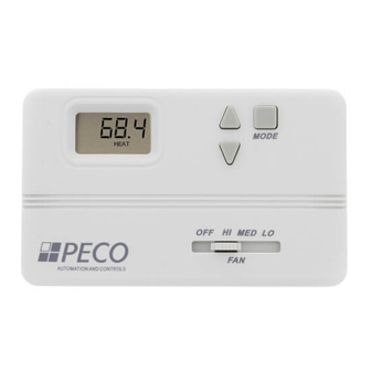
Installation Instructions
INSTALLATION
1. Install the T168 with the two furnished mounting screws to a
standard 4 1/16" x 2 1/8" square device box with a 2" x 4" adapter
ring.
2. For wall installations, mount the thermostat on an inside wall
approximately 5 feet above the floor. The locations should
provide circulation at an average room temperature. Avoid direct
sunlight or sources of hot or cold air in the room.
3. Remove the cover. Mount thermostat base assembly to the
outlet box using screws provided. Tighten the screws evenly but
do not overtighten. Connect wires per wiring diagram.
4. To use a remote sensor on units with local sensing capability,
remove jumper JP-1 to disable local sensing. Failure to remove
JP-1 will cause improper operation of thermostat.
5. Connecting a jumper between terminals 16 and 17 will disable
the secondary output and change the main output to heat mode.
6. Connection of a 24 VAC set back signal will force the control
into unoccupied mode (see diagram). Pressing an arrow key or
the mode buttons on the thermostat cover will disable the
setback input for one hour.
7. Remove the LCD plastic protective film to complete the
installation. Reinstall the cover assembly. Install cover locking
screw provided.
8. Checkout: After wiring and installation are complete, energize
the system and check the operation. Adjust the thermostat as
necessary to complete at least one cycle. Be sure the thermostat
and all other equipment are functioning correctly.
CAUTI O N
· Use Copper wire only, insulate or wire
nut all un-used leads.
· Care should be used to avoid
elecrostatic
microprocessor.
· This unit has configuration dip switches
and jumpers. You may need to reconfigure
thermostat for your application.
MOUNTING
discharge
to
the
0-10 VDC/4-20mA Thermostat
· READ THESE INSTRUCTIONS CAREFULLY BEFORE ATTEMPTING
TO INSTALL, OPERATE OR SERVICE THIS THERMOSTAT.
· Failure to observe safety information and comply with instructions
could result in PERSONAL INJURY, DEATH AND/OR PROPERTY
DAMAGE.
· To avoid electrical shock or damage to equipment, disconnect power
before installing or servicing.
· To avoid electric shock or damage to equipment, use only wiring
with insulation rated for full thermostat operating voltage.
· To avoid potential fire and/ or explosion do not use in potentially
flammable or explosive atmospheres.
· Retain these instructions for future reference. This product, when
installed, will be part of an engineered system whose specifications
and performance characteristics are not designed or controlled by
PECO, Inc. You must review your application and national and local
codes to assure that your installation will be functional and safe.
WIRING DIAGRAM
ELECTRICAL RATING
ELECTRICAL RATINGS
Fan Switch (Terminals 1-4) Line Voltage Connections
Voltage
Inductive
FLA
LRA
N.A.
N.A.
24 VAC
120
5.8
34.8
240
2.9
17.4
277
2.4
14.4
©
Copyright 2005 PECO, Inc. All Rights Reserved P/N 68841 3220-1478 Rev 0 Page 1
T168
WARNING
Thermostatic
Resistive
Pilot
Switching/
Low Voltage
24 VA
N.A.
10 VA
6.0
125 VA
N.A.
5.0
125 VA
N.A.
4.2
125 VA
N.A.
Advertisement

Subscribe to Our Youtube Channel
Related Manuals for Peco T168


Summary of Contents for Peco T168
-
Page 1: Installation Instructions
Pilot Switching/ Low Voltage 24 VA N.A. N.A. 10 VA N.A. 24 VAC 34.8 125 VA N.A. 17.4 125 VA N.A. 14.4 125 VA N.A. © Copyright 2005 PECO, Inc. All Rights Reserved P/N 68841 3220-1478 Rev 0 Page 1... -
Page 2: Thermostat Operation
After three consecutive seconds on either arrow, the selected setpoint becomes effective and the display of the room temperate resumes. © Copyright 2005 PECO, Inc. All Rights Reserved P/N 68841 3220-1479 Rev 0 Page 2...
Need help?
Do you have a question about the T168 and is the answer not in the manual?
Questions and answers