Table of Contents
Advertisement
Quick Links
Advertisement
Table of Contents

Related Manuals for 3Com 3CBLSF26PWRH


Summary of Contents for 3Com 3CBLSF26PWRH
-
Page 1: User Guide
Baseline Switch 2226-SFP Plus Baseline Switch 2426-PWR Plus Baseline Switch 2250-SFP Plus User Guide 3CBLSF26H 3CBLSF26PWRH 3CBLSF50H Part No.: 10017022 Manual Version: 6W107 www.3com.com 3Com Corporation 350 Campus Drive, Marlborough, MA, USA 01752 3064... - Page 2 3Com Corporation. 3Com Corporation reserves the right to revise this documentation and to make changes in content from time to time without obligation on the part of 3Com Corporation to provide notification of such revision or change.
-
Page 3: About This Manual
About This Manual Organization 3Com Baseline Switch 2226/2250/2426 User Guide is organized as follows: Chapter Contents This chapter contains introductory information about the 1 Getting Started installation of the switch and how they can be used in your network. This chapter introduces the setting the menu items and 2 Connecting To the Web Interface buttons that are available on the Web interface. -
Page 4: Obtaining Documentation
Convention Description Means reader be careful. Improper operation may cause data loss or damage to equipment. Means a complementary description. Obtaining Documentation You can access the most up-to-date 3Com product documentation on the World Wide Web at this URL: http://www.3com.com. -
Page 5: Table Of Contents
Table of Contents 1 Getting Started···········································································································································1-1 Introducing the Switch·····························································································································1-1 Overview of the Switch ····················································································································1-1 Summary of Hardware Features ·····································································································1-1 Front View Detail ·····························································································································1-2 LED Status Indicators······················································································································1-3 System Specifications ·····················································································································1-4 Installing the Switch ································································································································1-5 Before You Begin ····························································································································1-5 Package Contents ···························································································································1-5 Positioning the Switch ·····················································································································1-5 Rack-Mounting or Free-Standing ····································································································1-6 Supplying Power to the Switch········································································································1-7... - Page 6 Creating VLANs·····························································································································3-19 Modifying VLAN·····························································································································3-19 Modifying Port VLAN Settings ·······································································································3-20 Renaming VLANs ··························································································································3-21 Removing VLANs ··························································································································3-21 Viewing VLAN Details····················································································································3-22 Viewing VLAN Port Details············································································································3-23 Aggregating Port ···································································································································3-24 Overview········································································································································3-24 LACP ·············································································································································3-24 Link Aggregation Types·················································································································3-24 Configuring Link Aggregation ········································································································3-25 Configuring LACP··························································································································3-28 Configuring STP····································································································································3-29 Configuring IGMP Snooping ·················································································································3-35 Defining IGMP Snooping ···············································································································3-35 Configuring ACL····································································································································3-36 Configuring MAC Based ACL········································································································3-36...
- Page 7 Save Configuration ························································································································3-79 Resetting the Switch······················································································································3-80 Managing System Files·························································································································3-80 Managing System Logs ························································································································3-83 Configuring Logging ······················································································································3-84 Viewing Logs ·································································································································3-85 Managing Switch Diagnostics ···············································································································3-86 Configuring Port Mirroring ·············································································································3-86 Configuring Cable Diagnostics ······································································································3-87 4 Troubleshooting ········································································································································4-1 Resetting to Factory Defaults··················································································································4-1 Forgotten Password ································································································································4-1 Reset the switch ······························································································································4-1 Configure a new user ······················································································································4-2 Forgotten Static IP Address ····················································································································4-2...
- Page 8 ICES Statement ······································································································································7-1 CE Statement (Europe)···························································································································7-1 VCCI Statement ······································································································································7-2 CCC Statement ·······································································································································7-2 8 List of the Hazardous Substances···········································································································8-1 9 Glossary ·····················································································································································9-1...
-
Page 9: Getting Started
Getting Started This manual applies to the Baseline Switch 2250-SFP Plus, Baseline Switch 2226-SFP Plus, and Baseline Switch 2426-PWR Plus, which are hereinafter referred to as the switch. This manual takes the Web interfaces of the Baseline Switch 2426-PWR Plus as an example. This chapter contains introductory information about the installation of the switch and how they can be used in your network. -
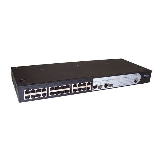
Page 10: Front View Detail
Feature Description Forwarding Modes Store and Forward. Duplex Modes Half and full duplex on all front panel ports. Supported on all ports. If fiber SFP transceivers are used, Auto MDI/MDIX Auto MDIX is not supported. Flow Control In full duplex operation all ports are supported. Traffic Prioritization Four traffic queues per port. -
Page 11: Led Status Indicators
Figure 1-3 Baseline Switch 2250-SFP Plus 50-Port—front panel. LED Status Indicators The Switch provides LED indicators on the front panel for your convenience to monitor the switch. Table 1-2 describes the meanings of the LEDs. Table 1-2 Description on the LEDs of the Switch Status Description The switch starts normally. -
Page 12: System Specifications
Status Description The link has not been established, either nothing is connected to the port, or there is a problem: Check that the attached device is powered Check that the cable or fiber is the correct type and is not faulty. For fiber connections, ensure that the receive (RX) and transmit (TX) cable connectors are not swapped. -
Page 13: Installing The Switch
Specification 2226-SFP 2426-PWR 2250-SFP Operating humidity 5% to 95% (noncondensing) Storage humidity 5% to 95% (noncondensing) Installing the Switch This section contains information that you need to install and set up the switch. It covers the following topics: Before You Begin Package Contents Positioning the Switch Rack-Mounting or Free-Standing... -
Page 14: Rack-Mounting Or Free-Standing
Water or moisture cannot enter the case of the unit. Air flow around the unit and through the vents on the side of the case is not restricted (3Com recommends that you provide a minimum of 25 mm (1 in.) clearance). -
Page 15: Supplying Power To The Switch
Power problems can be the cause of serious failures and downtime in your network. Ensure that the power input to your system is clean and free from sags and surges to avoid unforeseen network outages. 3Com recommends that you install power conditioning, especially in areas prone to blackout, power dips and electrical storms. -
Page 16: Checking For Correct Operation
If these do not resolve the issue: Check the 3Com Knowledgebase for a solution. To visit the 3Com Knowledgebase Web site, start your Web browser, and then enter http://knowledgebase.3com.com. Contact your 3Com network supplier for assistance. - Page 17 3CSFP91 SFP (SX) 3CSFP92 SFP (LX) To access the latest list of approved SFP transceivers for the switch on the 3Com Web site, enter this URL into your Internet browser: http://www.3com.com 3Com recommends using 3Com SFPs on the switch. If you insert an SFP transceiver that is not supported, the switch will not recognize it.
-
Page 18: Performing Spot Checks
At frequent intervals, you should visually check the switch. Regular checks can give you an early warning of a possible failure; any problems can then be attended to when there will be least effect on users. 3Com recommends periodically checking the items listed in Table 1-5. Table 1-5 Items to Check Item Operation Where possible, check that the cooling fan is operating by listening to the unit. -
Page 19: Automatic Ip Configuration Using Dhcp
Your DHCP server does not allow you to allocate static IP addresses. For most installations, 3Com recommends that you configure the switch IP information manually. This makes management simpler and more reliable as it is not dependent on a DHCP server, and eliminates the risk of the IP address changing. -
Page 20: Connecting To The Web Interface
Connecting To the Web Interface The switch has a built-in Web interface that you can use to set the user password, change the IP address that is assigned to the switch, and configure its advanced settings. This chapter introduces the setting the menu items and buttons that are available on the Web interface. The following topics are covered: Requirements for Accessing the Web Interface Choosing a Web Browser... -
Page 21: Default User And Password
Default User and Password If you intend to manage the switch or to change the default password, you must log in with a valid user name and password. The switch has one default user name. The default user is listed in Table 2-2. Table 2-2 Default User and Password User Name Default Password... - Page 22 Figure 2-2 Switch Screen Layout Table 2-3 Available Menu Items Menu Item Description Contains tabs that allow you to: Provide a summary of the switch’s basic settings and Device Summary versions of current components. Display the description for each color coded port. Save Configuration Saves the switch’s configuration Allows you to setup, modify, or view the IP configuration...
- Page 23 Menu Item Description Contains tabs that allow you to: Create a VLAN. Modify a VLAN. Modify VLAN membership for a port. VLAN Rename a VLAN. Remove a VLAN. Display VLAN membership for a port. Display VLAN information. Allows you to configure a Spanning Tree Protocol. Contains tabs that allow you to: Spanning Tree Display selected spanning tree information for every port.
-
Page 24: Buttons
Display selected cable diagnostics information for all Diagnostics ports. Display all cable diagnostics information for a single port. Displays 3Com contact information and describes how to use Help the online help system. Logout Allows you to securely log off the Web interface. -
Page 25: Configuring The Switch
Modifying System Access Removing System Access Viewing System Access Settings To ensure that unauthorized users do not access the Web interface, 3Com recommends that you set an admin password when you first configure the switch. Defining System Access The System Access Setup Page allows network administrators to define users, passwords, and access levels for users using the System Access Interface. -
Page 26: Modifying System Access
The System Access Setup Page contains the following fields: Table 3-1 System Access Setup Page item description Item Description User Name Defines the user name. The default value is admin. Defines the user access level. The lowest user access level is Monitor and the highest is Management. -
Page 27: Removing System Access
Removing System Access The System Access Remove Page allows network administrators to remove users from the System Access Interface. The last user with management access may not be deleted. Click Administration > System Access > Remove. The System Access Remove Page opens. Figure 3-3 System Access Remove Page Viewing System Access Settings The System Access Summary Page displays the current users and access levels defined on the switch. -
Page 28: Configuring Ip And Mac Address Information
Table 3-3 System Access Summary Page item description Item Description User Name Displays the user name. Access Level Displays the user access level. Configuring IP and MAC Address Information This section contains information for defining IP interfaces, and includes the following sections: Defining IP Address Configuring ARP Settings Configuring MAC Address Table... -
Page 29: Configuring Arp Settings
Configuring ARP Settings The Address Resolution Protocol (ARP) converts IP addresses into physical addresses, and maps the IP address to a MAC address. ARP allows a host to communicate with other hosts when only the IP addresses of its neighbors are known. This section includes the following topics: Defining ARP Settings Removing ARP Entries... - Page 30 Figure 3-7 ARP Entries Remove Page The ARP Entries Remove Page contains the following fields: Table 3-6 ARP Entries Remove Page item description Item Description Specifies the types of ARP entries that are cleared. The possible values are: Clear ARP Table None: Maintains the ARP entries.
-
Page 31: Configuring Mac Address Table
Figure 3-8 ARP Settings Summary Page The ARP Settings Summary Page contains the following fields: Table 3-7 ARP Settings Summary Page item description Item Description Interface Indicates the VLAN for which ARP parameters are defined. IP Address Indicates the IP address, which is associated with the MAC Address. Displays the station MAC address, which is associated in the ARP table MAC Address with the IP address. - Page 32 Adding MAC Addresses to the Address Table The Address Table Add Page allows the network manager to assign MAC addresses to ports with VLANs. Click Monitoring > Address Table > Add. The Address Table Add Page opens. Figure 3-9 Address Table Add Page The Address Table Add Page contains the following fields: Table 3-8 Address Table Add Page item description Item...
- Page 33 Figure 3-10 Address Table Aging Time Setup Page Removing MAC Addresses for the specific port The Port Remove Page allows the network manager to remove MAC Addresses for the specific port from the Address Table. Click Monitoring > Address Table > Port Remove. The Port Remove Page opens. Figure 3-11 Port Remove Page Select a port to remove MAC Addresses.
- Page 34 Select entries from the address table to be removed. Click Remove. Viewing Address Table Settings The Address Table Summary Page displays the current MAC address table configuration. Click Monitoring > Address Table > Summary. The Address Table Summary Page opens. Figure 3-13 Address Table Summary Page The Address Table Summary Page contains the following fields: Table 3-9 Address Table Summary Page item description...
-
Page 35: Configuring Port
Figure 3-14 Port Summary Page The Port Summary Page contains the following fields: Table 3-10 Port Summary Page item description Item Description Filters the list of MAC addresses displayed according to the type of MAC address configuration. Possible values are: State All: Displays all MAC addresses. - Page 36 Defining Port Settings The Port Setup Page allows network managers to configure port parameters for specific ports. Click Port > Administration > Setup. The Port Setup Page opens. Figure 3-15 Port Setup Page The Port Setup Page contains the following fields: Table 3-11 Port Setup Page item description Item Description...
- Page 37 Before manually setting a port to full-duplex mode, verify that the device connected to the port is also manually set to the same speed and duplex setting. If connecting link partners are left to auto- negotiate for a link manually set on this switch to full-duplex, they will always negotiate to half-duplex, resulting in a duplex mismatch.
-
Page 38: Configuring Poe
Item Description Displays the configured rate for the port. The port type determines what speed setting options are available. Port speeds can only be configured when auto negotiation is disabled. The possible field values are: Speed Auto: Use to automatically configure the port. 10M: Indicates the port is currently operating at 10 Mbps. - Page 39 Defining Port PoE The Port PoE Setup Page allows the network manager to configure port PoE settings. Click Port > PoE > Setup. The Port PoE Setup Page opens. Figure 3-18 Port PoE Setup Page The Port PoE Setup Page contains the following fields: Table 3-13 Port PoE Setup Page item description Item Description...
- Page 40 Click Port > PoE. The PoE Summary Page opens. Figure 3-19 Port PoE Summary Page The Port PoE Summary Page contains the following fields: Table 3-14 Port PoE Summary Page item description Item Description Indicates the power source status. The possible field values are: On: Indicates that the power supply unit is functioning.
-
Page 41: Viewing Port Statistics
Viewing Port Statistics The Port Statistics Summary Page contains fields for viewing information about switch utilization and errors that occurred on the switch. Click Port > Statistics > Summary. The Port Statistics Summary Page opens. Figure 3-20 Port Statistics Summary Page The Port Statistics Summary Page contains the following fields: Table 3-15 Port Statistics Summary Page item description Item... -
Page 42: Configuring Vlan
Item Description Displays the number of fragments (packets with less than 64 octets, Fragments excluding framing bits, but including FCS octets) received on the interface since the switch was last refreshed Displays the total number of received packets that were longer than 9216 octets. -
Page 43: Creating Vlans
Renaming VLANs Removing VLANs Viewing VLAN Details Viewing VLAN Port Details Creating VLANs The VLAN Setup Page allows the network administrator to create or rename VLANs. Click Device > VLAN > Setup. The VLAN Setup Page opens. Figure 3-21 VLAN Setup Page The VLAN Setup Page contains the following fields: Table 3-16 VLAN Setup Page item description Item... -
Page 44: Modifying Port Vlan Settings
Figure 3-22 Modify VLAN Page The Modify VLAN Page contains the following fields: Table 3-17 Modify VLAN Page item description Item Description Select a VLAN to Selects a VLAN to modify its settings. modify Selects the membership type for each port on the VLAN. The possible field values are: Untagged: Indicates the interface is an untagged member of the VLAN. -
Page 45: Renaming Vlans
Figure 3-23 Modify Port VLAN Page The Modify Port VLAN Page contains the following fields: Table 3-18 Modify Port VLAN Page item description Item Description Selects the membership type for each port on the VLAN. The possible field values are: Untagged: Indicates the interface is an untagged member of the VLAN. -
Page 46: Viewing Vlan Details
Figure 3-25 VLAN Remove Page Viewing VLAN Details The VLAN Detail Page provides information and global parameters on VLANs configured on the system. Click Device > VLAN > VLAN Detail. The VLAN Detail Page opens. Figure 3-26 VLAN Detail Page The VLAN Detail Page contains the following information: 3-22... -
Page 47: Viewing Vlan Port Details
Table 3-19 VLAN Detail Page item description Item Description Select a VLAN to Selects a VLAN to be display its settings Display Displays the membership type for each VLAN. The possible field values are: Untagged: Indicates the interface is an untagged member of the VLAN. Tagged: Indicates the interface is a tagged member of a VLAN. -
Page 48: Aggregating Port
Table 3-20 VLAN Port Detail Page item description Item Description Untagged Indicates the port is an untagged member of the VLAN. Membership Indicates the port is a tagged member of a VLAN. VLAN tagged frames are Tagged membership forwarded by the interface. The frames contain VLAN information. Aggregating Port Overview Link aggregation aggregates multiple physical Ethernet ports into one logical link, called a Link... -
Page 49: Configuring Link Aggregation
Among the ports in an aggregation group that are in up state, the system determines the mater port with one of the following settings being the highest (in descending order) as the master port: full duplex/high speed, full duplex/low speed, half duplex/high speed, half duplex/low speed. The ports with their rate, duplex mode and link type being the same as that of the master port are selected ports, and the rest are unselected ports. - Page 50 Click Port > Link Aggregation > Create. The Link Aggregation Create Page opens. Figure 3-28 Link Aggregation Create Page The Link Aggregation Create Page includes the following fields: Table 3-21 Link Aggregation Create Page item description Item Description Enter Aggregation Defines the group ID.
- Page 51 Figure 3-29 Link Aggregation Modify Page Removing Link Aggregation The Link Aggregation Remove Page allows the network manager to remove group IDs containing member ports. Click Port > Link Aggregation > Remove. The Link Aggregation Remove Page opens. Figure 3-30 Link Aggregation Remove Page Viewing Link Aggregation The Link Aggregation Summary Page displays the state of the current link aggregation.
-
Page 52: Configuring Lacp
Table 3-22 Link Aggregation Summary Page item description Item Description Group ID Displays the Link Aggregated Group ID. The field range is 1-6. Displays the type of link aggregation for the Group ID. The possible field Type value is Static or LACP. Ports Displays the member ports included in the specified LAG. -
Page 53: Configuring Stp
Figure 3-33 LACP Summary Page The LACP Summary Page contains the following fields: Table 3-24 LACP Summary Page item description Item Description Port-Priority Displays the LACP priority value for the port. Displays the administrative LACP timeout. The possible field values are: LACP Timeout Long: Specifies the long timeout value. - Page 54 network segment. All other ports are blocked, which means that they are prevented from forwarding traffic. The device supports the following STP versions: Classic STP: Provides a single path between end stations, avoiding and eliminating loops. Rapid STP: Detects and uses network topologies that provide faster convergence of the spanning tree, without creating forwarding loops.
- Page 55 Table 3-25 STP Global Setup Page item description Item Description Defines whether STP is enabled on the switch. The possible field values are: Spanning Tree Disable: Disables STP and RSTP on the switch. State Classic: Enables STP on the switch. RSTP: Enables RSTP on the switch.
- Page 56 Modifying STP Interface Parameters The STP Interface Parameters Modify Page allows network managers to modify STP parameters to specific interfaces. Click Device > Spanning Tree > Modify. The STP Interface Parameters Modify Page opens. Figure 3-35 STP Interface Parameters Modify Page The STP Interface Parameters Modify Page contains the following fields: Table 3-26 STP Interface Parameters Modify Page item description Item...
- Page 57 Item Description Defines the port contribution to the root path cost. When Default Path Cost is disabled, you can configure it; when Default Path Cost is enabled, you can not configure it , and the possible field values are: Path Cost 65535: Indicates Path Cost Default Values is short.
- Page 58 Item Description Indicates if the interface is acting as the root port of the switch. The possible field values are: Root Guard Enabled: Indicates Root Guard is enabled on the port Disabled: Indicates Root Guard is disabled on the port. Displays the current STP state of a port.
-
Page 59: Configuring Igmp Snooping
Configuring IGMP Snooping This section contains information for configuring IGMP Snooping. When IGMP Snooping is enabled, all IGMP packets are forwarded to the CPU. The CPU analyzes the incoming packets and determines: Which ports want to join which Multicast groups. Which ports have Multicast routers generating IGMP queries. -
Page 60: Configuring Acl
Item Description Select VLAN ID Specifies the VLAN ID Defines whether IGMP snooping is enabled on the VLAN. The possible field values are: IGMP Snooping Enabled: Enables IGMP Snooping on the VLAN. Status Disabled: Disables IGMP Snooping on the VLAN. This is the default value. - Page 61 Table 3-29 MAC Based ACL Setup Page item description Item Description Selection ACL Selects an existing MAC-based ACL to which rules are to be added. Defines a new user-defined MAC-based Access Control List. The options are as follows: ACL Priority: Sets the ACL priority. The possible field values are 1-100. Create ACL Rule Priority Type: Sets the rule priority type.
- Page 62 To define a new MAC-based ACL rule: Select Selection ACL. Select the ACL from the list. Define the fields for the new ACL rule. Click Apply. Modifying MAC Based ACL The MAC Based ACL Modify Page allows the network administrator to modify an existing MAC-based ACL rule.
- Page 63 Table 3-30 MAC Based ACL Remove Page item description Item Description ACL Name Selects a MAC-based ACL for removal. Remove ACL Enables the ACL to be removed. To remove MAC-based ACL: Select the ACL Name to be removed Check Remove ACL. Click Remove.
-
Page 64: Configuring Ip Based Acl
Item Description Classifies traffic based on the CoS tag value. CoS Mask Displays the CoS mask used to filter CoS tags. Ethertype Provides an identifier that differentiates between various types of protocols. Indicates the ACL forwarding action. In addition, the port can be shut down, a trap can be sent to the network administrator, or packet is assigned rate limiting restrictions for forwarding. - Page 65 Item Description Defines the protocol in the rule to which the packet is matched. The possible fields are: Select from List: Selects a protocol from a list by which packets are Protocol matched to the rule. Protocol ID: Selects a protocol ID from a list by which packets are matched to the rule.
- Page 66 Select Selection ACL. Select the ACL from the list. Define the fields for the new ACL rule. Click Apply. Modifying IP Based ACL The IP Based ACL Modify Page allows the network administrator to modify IP Based ACL rules. Click Device > ACL > IP Based ACL > Modify. The IP Based ACL Modify Page opens. Figure 3-43 IP Based ACL Modify Page The description of parameters in the page refers to Defining IP Based ACL.
- Page 67 Table 3-33 IP Based ACL Remove Page item description Item Description ACL Name Selects an IP-based ACL for removal. Remove ACL Enables the ACL to be removed. To remove an IP-based ACL: Select an ACL Name to be removed. Check Remove ACL. Click Remove.
-
Page 68: Configuring Acl Binding
Item Description Source IP Address Matches the source IP address to which packets are addressed to the ACL. Source Mask Indicates the source IP address mask. Destination IP Matches the destination IP address to which packets are addressed to the Address ACL. - Page 69 Removing ACL Binding The ACL Binding Remove Page allows the network administrator to remove user-defined ACLs from a selected interface. Click Device > ACL > ACL Binding > Remove. The ACL Binding Remove Page opens. Figure 3-47 ACL Binding Remove Page The ACL Binding Remove Page contains the following fields: Table 3-36 ACL Binding Remove Page item description Item...
-
Page 70: Configuring Qos
Table 3-37 ACL Binding Summary Page item description Item Description MAC-based ACL Displays the MAC based ACL to which the interface is assigned. IP-based ACL Displays the IP based ACL to which the interface is assigned Configuring QoS Quality of Service (QoS) provides the ability to implement QoS and priority queuing within a network. For example, certain types of traffic that require minimal delay, such as Voice, Video, and real-time traffic can be assigned a high priority queue, while other traffic can be assigned a lower priority queue. -
Page 71: Configuring Queue Algorithm
Table 3-38 CoS Setup Page item description Item Description Specifies if QoS is enabled on the switch. The possible values are: Disabled: Restores the switch factory defaults for QoS values and QoS Mode disables configure QoS values on the switch. Enabled: Enables configure QoS values on the switch. -
Page 72: Configuring Cos To Queue
Figure 3-51 Queue Setup Page The Queue Setup Page contains the following fields: Table 3-40 Queue Setup Page item description Item Description This highest queue is transmitted first if any packets are in the highest HQ-WRR queue. When the highest queue is exhausted, the remaining queues are served by WRR. -
Page 73: Configuring Dscp To Queue
Table 3-41 CoS to Queue Setup Page item description Item Description Restores the switch factory defaults for mapping CoS values to forwarding Restore Defaults queues. Specifies the CoS priority tag values, where 0 is the lowest and 7 is the Class of Service highest. - Page 74 Figure 3-54 DSCP to Queue Setup Page The DSCP to Queue Setup Page contains the following fields: Table 3-43 DSCP to Queue Setup Page item description Item Description Restores the switch factory defaults for mapping DSCP values to a traffic Restore Defaults forwarding queue.
-
Page 75: Configuring Trust Mode
Table 3-44 DSCP to Queue Summary Page item description Item Description DSCP Displays the incoming packet’s DSCP value. Indicates the CoS value forwarding queue to which the DSCP priority is mapped. The possible field values are 0-7. Configuring Trust Mode The Trust Setup Page contains information for configuring trust mode on the switch. - Page 76 Figure 3-57 Bandwidth Setup Page The Bandwidth Setup Page contains the following fields: Table 3-46 Bandwidth Setup Page item description Item Description Enable Ingress Enables setting an Ingress Rate Limit. Ingress Rate Limit Rate Defines the ingress traffic limit for the port. The field range of nomal port is Limit Ingress 3500 - 100,000 kbits per second, and the field range of combo port is 3500...
-
Page 77: Configuring Voice Vlan
Figure 3-58 Bandwidth Summary Page The Bandwidth Summary Page contains the following fields: Table 3-47 Bandwidth Summary Page item description Item Description Indicates the ingress rate limiting status on the interface. The possible field values are: Ingress Status Enabled: Ingress rate limiting is enabled on the interface. Rate Disabled: Ingress rate limiting is disabled on the interface. - Page 78 There are two operational modes for IP Phones: IP phones are configured with VLAN-mode as enabled, ensuring that tagged packets are used for all communications. If the IP phone’s VLAN-mode is disabled, the phone uses untagged packets. The phone uses untagged packets while retrieving the initial IP address through DHCP.
- Page 79 Defining Voice VLAN Global Settings The Voice VLAN Setup Page provides information for enabling and defining Voice VLAN globally on the switch. Click Device > QoS > VoIP Traffic Setting > Setup. The Voice VLAN Setup Page opens. Figure 3-60 Voice VLAN Setup Page The Voice VLAN Setup Page contains the following fields: Table 3-49 Voice VLAN Setup Page item description Item...
- Page 80 Table 3-50 Voice VLAN Port Setup Page item description Item Description Specifies the Voice VLAN mode. The possible field values are: No Changes: Maintains the current Voice VLAN port settings. None: Indicates that the selected port will not be added to a Voice VLAN. This is the default value.
- Page 81 Figure 3-63 Voice VLAN OUI Summary Page Viewing Voice VLAN The Voice VLAN Summary Page contains information about the Voice VLAN currently enabled on the switch, including the ports enabled and included in the Voice VLAN. Click Device > QoS > VoIP Traffic Setting. The Voice VLAN Summary Page opens. Figure 3-64 QoS VoIP Summary Page The Voice VLAN Summary Page contains the following fields: Table 3-51 Voice VLAN Summary Page item description...
-
Page 82: Configuring Snmp
Configuring SNMP Simple Network Management Protocol (SNMP) provides a method for managing network devices. The switch supports the following SNMP versions: SNMP version 1 SNMP version 2c The SNMP agents maintain a list of variables, which are used to manage the switch. The variables are defined in the Management Information Base (MIB). -
Page 83: Removing Snmp Communities
Item Description Selects pre-defined community strings. The possible field values are: Standard Public: Displays the pre-defined public community string name. Private: Displays the pre-defined private community string name. User Defined Defines a user-defined community string name. Defines the access rights of the community. The possible field values are: Read Only: Management access is restricted to read-only, and changes Access Mode cannot be made to the community. -
Page 84: Removing Snmp Traps
Figure 3-67 SNMP Traps Setup Page The SNMP Traps Setup Page contains the following fields: Table 3-53 SNMP Traps Setup Page item description Item Description Recipients IP Address Defines the IP address to which the traps are sent. Community String Defines the community string of the trap manager. -
Page 85: Configuring Lldp
Configuring LLDP LLDP Overview The Link Layer Discovery Protocol (LLDP) operates on the data link layer. With LLDP, a device can store and maintain information about itself and the directly-connected neighbor devices for network administrators to check link status. LLDP Operating Mode LLDP can operate in one of the following modes: TxRx: A port in this mode sends and receives LLDPDUs. - Page 86 Item Description Set the interval for sending LLDPDUs. A port operating in TxRx mode or Tx mode sends LLDPDUs to its directly Transmit Interval connected device periodically. By default, the interval is 30 seconds. Set the TTL multiplier. You can configure the TTL of locally sent LLDPDUs to determine how long they can be saved on a neighbor device by setting the TTL hold multiplier.
-
Page 87: Configuring Port-Level Lldp Parameters
Item Description Set the delay before sending next LLDPDUs. This parameter is introduced to avoid sending excessive number of Send packet Delay LLDPDUs caused by frequent local configuration changes. By default, the delay is 2 seconds. Set the interval for sending LLDP remote change trap. Trap Interval By default, the interval for sending trap is 5 seconds. - Page 88 Table 3-55 Port-Level LLDP Parameters Page item description Item Description Enable/disable LLDP on a port. Two options are available: Enabled: Enables LLDP on the port. LLDP Disabled: Disables LLDP on the port. By default, LLDP is enabled on a port. Set the LLDP operating mode.
-
Page 89: Viewing Lldp Information
Item Description The IEEE 802.1 defined LLDP TLVs supported by the device include the following: Port Vlan ID: Checked to include the VLAN ID(s) on the port. Protocol Vlan ID: Checked to include the IDs of the IEEE 802.1 protocol VLAN(s) on the port. Vlan Name: Checked to include the VLAN names on the port. - Page 90 Figure 3-71 Global LLDP Information and Received LLDP Information Page The Global LLDP Information and Received LLDP Information Page contains the following fields: Table 3-56 Global LLDP Information and Received LLDP Information Page item description Item Description Added Neighbor Total number of discovered neighbors Deleted Neighbor Total number of deleted neighbors Discarded LLDP's Packet...
-
Page 91: Managing Switch Security
Figure 3-72 Port-Level LLDP Information Page Select a port, and then the LLDP information of the port will be displayed in the Summary box. The displayed information includes LLDP status and statistics of the port and the status of the TLVs sent by the port. - Page 92 Defining 802.1X Authentication The 802.1X Setup Page contains information for configuring 802.1X global settings on the switch and defining specific 802.1X setting for each port individually. Click Security > 802.1X > Setup. The 802.1X Setup Page opens. Figure 3-73 802.1X Setup Page The 802.1X Setup Page contains the following fields: Table 3-57 802.1X Setup Page item description Item...
- Page 93 Item Description Specifies whether the Guest VLAN is enabled on the port. The possible field values are: Enabled: Enables using a Guest VLAN for unauthorized ports. If a Guest VLAN Guest VLAN is enabled, the unauthorized port automatically joins the VLAN selected from the Guest VLAN ID dropdown list.
-
Page 94: Defining Radius Client
Item Description Reauthentication Displays the time span (in seconds) in which the selected port is Period reauthenticated. The field default is 3600 seconds. Defining Radius Client Remote Authentication Dial-in User Service (Radius) is a logon authentication protocol that uses software running on a central server to control access to Radius-aware devices on the network. An authentication server contains a database of multiple user name/password pairs with associated privilege levels for each user or group that require management access to a switch. -
Page 95: Configuring Ldb
Configuring LDB If your switch is not enabled with an advanced authentication method, like RADIUS, for authentication, you can use the local database (LDB) feature to perform local authentication (port-based authentication).After the switch is enabled with the LDB feature and related access rights are configured, a user trying to access an address through the switch will be authenticated. - Page 96 Item Description Set the authentication sleep period. 5 minutes by default Sleep Period Note: Within the authentication sleep period, no users on this port are allowed to try to pass authentication. Set the aging time. 1 hour by default Aging time Note: If there is no traffic of authenticated users through a port within the aging time, the port will be aged out and enters the Block state.
- Page 97 Figure 3-79 Configure a user account To add a user account, click Add. To modify the password of a user, select the user, enter a new password in the Password text box, and click Modify. Displaying LDB On this page, you can view the LDB mode, state and user passing authentication on each port. Select Security >...
-
Page 98: Configuring Broadcast Storm Control
Item Description Displays the current state of the port. NORMAL: The user on the port passed the authentication. BLOCK: The port is in the initial state after the LDB feature is Current Port State enabled or the port is aged out. SLEEP: The number of the user’s authentication attempts exceeded the preset maximum value. -
Page 99: Managing System Information
Table 3-62 Broadcast Storm Setup Page item description Item Description Defines whether forwarding broadcast packet type is enabled on the interface. The possible field values are: Disabled: Disables broadcast control on the selected port. This is the Broadcast Mode default. Broadcast: Enables broadcast control on the selected port. -
Page 100: Viewing Basic Settings
Defines the location where the system is currently running. System Contact Defines the name of the contact person. Product 3C Number Displays the 3Com switch 3C number MAC Address Displays the switch MAC address. Displays the amount of time since the most recent switch reset. The... -
Page 101: Configuring System Name
Item Description Enables polling the ports for port information including speed, utilization Poll Now and port status. Viewing Color Keys The Color Key Page provides information regarding the RJ45 or SFP port status on the switch. The various colors key indicate the port status, speed and link of a selected port. Click Device Summary >... -
Page 102: Configuring System Time
Figure 3-85 System Name Page The System Name Page includes the following fields: Table 3-66 System Name Page item description Item Description System Name Defines the user-defined switch name. The field length is 0-30 characters Defines the location where the system is currently running. The field length System Location is 0-80 characters. -
Page 103: Save Configuration
Figure 3-86 System Time Setup Page The System Time Setup Page contains the following fields: Table 3-67 System Time Setup Page item description Item Description Current Time Displays the current time in Mon-Day-Year Hour:Min:Sec. Time zone Local Time zone from GMT in which switch is operating. Configure Daylight When day light saving is enabled, one hour will be added to time zone Saving Time Manually... -
Page 104: Resetting The Switch
Click Save Configuration. The Save Configuration Page opens. Figure 3-87 Save Configuration Page Click OK. The configuration is saved. Resetting the Switch The Reset Page restores the switch factory defaults. To prevent the current configuration from being lost, use the Save Configuration Page to save all user-defined changes to the flash memory before resetting the switch. - Page 105 Running Configuration File: Contains all configuration file commands, as well as all commands entered during the current session. After the switch is powered down or rebooted, all commands stored in the Running Configuration file are lost. Image files: Software upgrades are used when a new version file is downloaded. The file is checked for the right format, and that it is complete.
- Page 106 Figure 3-90 Restore Files Page The Restore Files Page contains the following fields: Table 3-69 Restore Files Page item description Item Description Download via TFTP Enables to download files via TFTP. Download via HTTP Enables to download files via HTTP. Specifies the TFTP Server IP Address from which the TFTP Server IP Address configuration files are downloaded.
-
Page 107: Managing System Logs
Item Description Specifies the TFTP Server IP Address from which the image files TFTP Server IP Address are downloaded. Specifies file name for the downloaded image file. Click Browse to Source File Name locate the image file on your computer. Activating Image Files The Active Image Page allows network managers to select and reset the Image files. -
Page 108: Configuring Logging
Table 3-72 System Log Severity Levels Severity Level Message Emergency Highest (0) The system is not functioning. Alert The system needs immediate attention. Critical The system is in a critical state. Error A system error has occurred. Warning A system warning has occurred. The system is functioning properly, but a system Notice notice has occurred. -
Page 109: Viewing Logs
Table 3-73 Logging Setup Page item description Item Description Specifies if device local logs for Cache and servers are enabled. Console logs are enabled by default. Severity level: Specifies the minimum severity level for which a message will be logged. When a severity level is selected, all severity level choices above the selection are selected automatically. -
Page 110: Managing Switch Diagnostics
Table 3-74 Logging Display Page item description Item Description Save Preview Saves the displayed Log table to a Web (html) page. Clear Logs Clears all logs Log Time Displays the time at which the log was generated. Severity Displays the log severity. Description Displays the log message text. -
Page 111: Configuring Cable Diagnostics
Table 3-75 Port Mirroring Setup Page item description Item Description Defines the monitor port (destination port) or mirror port (source port). The possible values are: Monitor: Defines the port as the monitor port. Select port type Mirror: Defines the port as the mirrored port to be monitored and indicates the traffic direction to be monitored. - Page 112 Figure 3-97 Cable Diagnostic Page Select a port to be tested. Click Apply. The test results of the port are displayed in the textbox. Viewing Cable Diagnostics The Cable Diagnostics Summary Page displays information on Test Result, Cable Fault Distance, or Last Update for every port on the switch.
-
Page 113: Troubleshooting
This chapter lists some issues that you may encounter while installing, using, and managing the switch, with suggested courses of corrective action to take. If you encounter an issue that is not listed here and you cannot solve it, check the 3Com Knowledgebase at http://knowledgebase.3com.com.before contacting your local technical support representative. -
Page 114: Configure A New User
The correct category of cable is being used for the required link speed. Category 3 cables can be used for 10BASE-T operation only. Category 5 cable is required for 100BASE-TX or 1000BASE-T. 3Com recommends Category 5e or 6 cables for 1000BASE-T operation. A fiber cable is connected, but the Module Active LED is off Verify that: The fiber cable is in good condition. - Page 115 Refer to the documentation that accompanies the switch for information on disabling the broadcast operation. If the problem persists and the unit still does not operate successfully, contact your 3Com network supplier with the following information before returning the unit: Product number and serial number (printed on a label supplied with the unit).
-
Page 116: Cli Reference Guide
CLI Reference Guide This chapter describes using the Command Line Interface (CLI) to manage the switch. The switch is managed through the CLI from a direct connection to the switch console port. Getting Started with the Command Line Interface Using the CLI, network managers enter configuration commands and parameters to configure the switch. -
Page 117: Cli Features
CLI Features Online Help CLI provides two types of online help: complete online help and partial online help. They assist you with your configuration. Complete online help Enter a "?" character in any view on your terminal to display all the commands available in the view and their brief descriptions. -
Page 118: Command History
the keywords that match the input characters will be displayed on the terminal screen if the input characters match more than one keyword. Command History CLI can store the latest executed commands as history commands so that users can recall and execute them again. -
Page 119: Command Edit
Error message Description found at '^' position. An error is found at '^' position. Command Edit The CLI provides basic command edit functions and supports multi-line editing. The maximum number of characters a command can contain is 254. Table 5-3 lists the CLI edit operations. Table 5-3 Edit operations Press…... -
Page 120: Display Management-Vlan
Example # Display the IP address information about the switch. <Command-Line> display ip Vlan-interface1 current state: UP Line protocol current state : UP Hardware address is 0800-1234-5656 Internet address is 192.168.0.234/24 display management-vlan Syntax display management-vlan View User view Parameter None Description Use the display management-vlan command to display the information of the management VLAN,... -
Page 121: Display Version
display version Syntax display version View User view Parameter None Description Use the display version command to display the system information (such as the version information) about the switch. Example # Display the system information about the switch. <Command-Line> display version ip address Syntax ip address ip-address net-mask... -
Page 122: Ip Gateway
undo ip address dhcp-alloc View User view Parameter None Description Use the ip address dhcp-alloc command to configure the switch to obtain an IP address through DHCP. Use the undo ip address dhcp-alloc command to cancel the configuration. Example # Configure the switch to obtain an IP address through DHCP. <Command-Line>... -
Page 123: Management-Vlan
Parameter name: Web user name, which ranges from 1 to 8. password: Web user password, which ranges from 1 to 8. level: Web user level, which ranges from 0 to 1.0 is guest, 1 is admin. Description Use the localuser command to configure a Web user for the switch. Use the undo localuser command to remove the Web user. -
Page 124: Ping
View User view Parameter interface-number: Ethernet port number Description Use the management-vlan port command to add Ethernet ports of the switch to the management VLAN. By default, all Ethernet ports of a switch belong to management VLAN 1. Example # Configure VLAN 10 as the management VLAN, and add Ethernet 0/1 through Ethernet 0/5 of the switch to the management VLAN. -
Page 125: Quit
Example # Check the reachability of the host with IP address 192.168.0.100. <Command-Line> ping 192.168.0.100 PING 192.168.0.100: 56 data bytes, press CTRL_C to break Reply from 192.168.0.100 : bytes=56 sequence=1 ttl=255 time = 1ms Reply from 192.168.0.100 : bytes=56 sequence=2 ttl=255 time = 2ms Reply from 192.168.0.100 : bytes=56 sequence=3 ttl=255 time = 1ms Reply from 192.168.0.100 : bytes=56 sequence=4 ttl=255 time = 3ms Reply from 192.168.0.100 : bytes=56 sequence=5 ttl=255 time = 2ms... -
Page 126: Restore
Parameter None Description Use the reboot command to restart the switch. Example # Restart the switch. <Command-Line> reboot This will reboot device. Continue? [Y/N] restore Syntax restore default View User view Parameter None Description Use the restore command to reset the switch to factory defaults. Example # Reset the switch to factory defaults. -
Page 127: Tftp Update
Example # Save current configuration of the switch. <Command-Line> save This will save the configuration in the FLASH memory Are you sure?[Y/N]y Now saving current configuration to FLASH memory Please wait for a while... Current configuration saved to FLASH memory successfully tftp update Syntax tftp update ip-address filename... -
Page 128: Safety Information
Important Safety Information Please refer to the safety information found in the 3Com Switch Family Safety and Regulatory Information manual included with this product. You can find the 3Com Switch Family Safety and Regulatory Information manual that was included with your switch. -
Page 129: Regulatory Notices
This Class A digital apparatus complies with Canadian ICES-003. Cet appareil numérique de la Classe A est conforme à la norme NMB-003 du Canada. CE Statement (Europe) EU Representative: 3Com Europe Limited Peoplebuilding 2, Peoplebuilding Estate Maylands Avenue Hemel Hempstead, Hertfordshire... -
Page 130: Vcci Statement
Warning: This is a class A product. In a domestic environment this product may cause radio interference in which case the user may be required to take adequate measures. A copy of the signed Declaration of Conformity can be downloaded from the Product Support web page for the Switch at http://www.3com.com. VCCI Statement CCC Statement 此为... -
Page 131: List Of The Hazardous Substances
List of the Hazardous Substances This document contains information required by the People's Republic of China as per their legislation titled "Management Methods for Controlling Pollution by Electronic Information Products". 产品中有毒有害物质清单全集如下表所示。 有毒、有害物质和元素 部件名称 汞 镉 六价铬 多溴联苯 多溴代二本 铅 (Pb) (Hg)... - Page 132 有毒、有害物质和元素 部件名称 汞 镉 六价铬 多溴联苯 多溴代二本 铅 (Pb) (Hg) (Cd) (Cr (VI) ) (PBB) 醚(PBDE) 〇 〇 〇 〇 〇 内部电源4 〇 〇 〇 〇 〇 冗余电源1 〇 〇 〇 〇 〇 冗余电源2 〇 〇 〇 〇 〇 摄像机 〇...
-
Page 133: Glossary
Glossary Table 9-1 Glossary Item Description The IEEE specification for 10 Mbps Ethernet over Category 3, 4 or 5 10BASE-T twisted pair cable. The IEEE specification for 100 Mbps Fast Ethernet over Category 5 100BASE-TX twisted-pair cable. IEEE 802.3z specification for Gigabit Ethernet over 9/125 micron core 1000BASE-LX single-mode fiber cable. - Page 134 Item Description One of five grades of Twisted Pair (TP) cabling defined by the EIA/TIA-568-B standard. Category 6 can be used in Ethernet Category 6 Cables (10BASE-T), Fast Ethernet (100BASE-TX) and Gigabit Ethernet (1000BASE-T) networks, and can transmit data at speeds of up to 1000 Mbps.
- Page 135 Item Description Local Area Network. A network of end stations (such as PCs, printers, servers) and network devices (hubs and switches) that cover a relatively small geographic area (usually not larger than a floor or building). LANs are characterized by high transmission speeds over short distances (up to 1000 meters).
- Page 136 Item Description Enables the monitoring of port traffic by attaching a network analyzer to Traffic Monitoring one switch port, in order to monitor the traffic of other ports on the switch. A Virtual LAN is a collection of network nodes that share the same collision domain regardless of their physical location or connection point VLAN in the network.
Need help?
Do you have a question about the 3CBLSF26PWRH and is the answer not in the manual?
Questions and answers