
Related Manuals for Bertazzoni CTYK..U7X(2,5)A


Summary of Contents for Bertazzoni CTYK..U7X(2,5)A
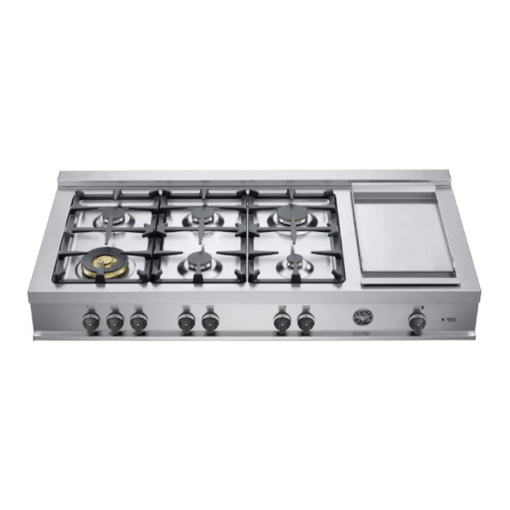
- Page 1 Installation, Service and User Instructions BUILT-IN GAS/ELECTRIC COOKTOP BERTAZZONI DIMENSIONS: 48’’( ) (W) x 25 ) (D) 1216 mm 1/8’’ 640mm MODELs: CTYK..U7X(2,5)A 310682...
-
Page 2: Important - Please Read And Follow
IMPORTANT - PLEASE READ AND FOLLOW -Before beginning installation, please read these instructions completely and carefully. -Do not remove permanently affixed labels, warnings, or plates from the product. This may void the warranty. -Please observe all local and national codes and ordinances. -Please ensure that this product is properly grounded. - Page 3 WARNING Read this instruction booklet before installing and using the appliance. The manufacturer will not be responsible for any damage to property or to persons caused by incorrect installation or improper use of the appliance. The manufacturer reserves the right to make changes to its products when considered necessary and useful, without affecting the essential safety and operating characteristics.
-
Page 4: Backguard Installation Instruction
WARNING: Do not use aerosol sprays in the vicinity of this appliance while it is in operation Requirements Room ventilation – Location and venting. ATTENTION: An exhaust fan may be used with the appliance; in each case it shall be installed in conformity with the appropriate national and local standards. - Page 5 ELECTRIC GRIDDLE INSTALLATION INSTRUCTIONS For installation the electric griddle, see the instructions indicated in the figure...
- Page 6 INSTALLATION SIDE-BY-SIDE TO KITCHEN CABINET 1. This range may be installed directly adjacent to existing 36" (91.5 cm) high cabinets. IMPORTANT: The top border of the worktop should be at the same level of the adjacent cabinet countertop. This can be accomplished by raising the unit using the adjustment spindles on the legs.
-
Page 7: Electrical Connection
COOKER HOOD INSTALLATION The bottom of the hood should be 25 ½ " (65 cm) min. to 31 ½ " (80 cm) above the countertop. Refer to the rangehood installation instructions for additional information. These dimensions provide for safe and efficient operation of the hood. ELECTRICAL CONNECTION This unit is manufactured for a polarized, grounded 120 volt/60 Hz, 16 amp system. -
Page 8: Gas Connection
Wiring diagram For freestanding gas range model CTYK..U7X(2,5)A CAUTION: label all wires prior to disconnection when servicing controls. Wiring errors can cause improper and dangerous operation. Verify proper operation after servicing. GAS CONNECTION All gas connections must be made according to national and local codes. TheThis gas supply (service) line must be the same size or greater than the inlet line of the appliance. -
Page 9: Final Preparation
valve during any pressure testing of the gas supply piping system at test pressures equal to or less than 1/2 psig (3.45 kPa). 3. Flexible Connections: a) If the unit is to be installed with flexible couplings and/or quick disconnect fittings, the installer must use a heavy-duty, AGA design-certified commerciai flexible connector of at least 1/2"... -
Page 10: Adapting To Different Types Of Gas
- CHANGING THE NOZZLES FOR USE WITH OTHER TYPES OF GAS: To change the nozzles of the burners use the following procedure: Lift up the burners and unscrew the nozzles ( Fig.) using an adjustable spanner of 7 mm and change the nozzles with those designed for the new gas supply according to the information given in TABLE shown below. -
Page 11: Regulation Of Burners
REGULATION OF BURNERS Work surface burner adjustment: follow the instructions below to adjust the work surface burner minimum: 1) Light the burner and set the knob to the MINIMUM position (small flame). 2) Remove the knob of the valve that is press fit on the rod of that valve. 3) The cooker is equipped with safety valves, use a small slotted screwdriver the choke valve located on the valve body and turn the choke screw to the right or left until the burner flame is adjusted to minimum 4) Make sure that the flame does not go out when switching quickly from the MAXIMUM to the MINIMUM position. -
Page 12: Control Panel Description
Do not to cover the burners of cooktop with aluminium paper Keeping appliance area clear and free from combustible materials, gasoline and other flammable vapors and liquid. Do not store dangerous or flammable material in the cabinet areas above appliance; store them in a safe place in order to avoid potential hazards. -
Page 13: Using Burners
USING BURNERS A diagram is etched on the control panel above each knob which indicates which burner corresponds to that knob. (flame) Manual ignition: Manual ignition is always possible even when the power is cut off or in the event of prolonged power failure. Turn the knob that corresponds to the burner selected counterclockwise to the MAXIMUM position at the etched star (large flame) and place a lit match up to the burner. -
Page 14: Using The Electric Griddle
USING THE ELECTRIC GRIDDLE WARNING The griddle element is hot after use. Allow sufficient time for griddle components cool before cleaning. The electric griddle element is rated 120 volts AC 1100 watts. Seasoning the griddle Before using the griddle for the first time, it must be seasoned. If the griddle has not been used for a period of time, it should be reseasoned. -
Page 15: Cleaning The Appliance
CLEANING THE APPLIANCE: Never use abrasive cleaners Before cleaning the appliance it should be disconnected from the power supply. Cleaning the work surface: periodically clean the burner heads, the cast iron pan supports and the burner caps using warm water. Any spillage must always be removed as soon as possible using a rag. -
Page 16: After-Sale Service
Please note here below details for after save service. Refer to warranty certificate for warranty condiftions Dealer /Importer: Name, address, phone SERVICE CENTERS Name Phone MANUFACTURER: BERTAZZONI SPA VIA PALAZZINA, 8 – 42016 – GUASTALLA (REGGIO E.) ITALY Tel. +39 0522/226411 – telefax +39 0522/226440 – http://www.bertazzoni-italia.com...
Need help?
Do you have a question about the CTYK..U7X(2,5)A and is the answer not in the manual?
Questions and answers