Fluke 374 Calibration Manual
Clamp meter
Hide thumbs
Also See for 374:
- User manual (33 pages) ,
- Specifications (2 pages) ,
- User manual (32 pages)

Related Manuals for Fluke 374


Summary of Contents for Fluke 374
- Page 1 374/375/376 Clamp Meter Calibration Manual December 2010 © 2010 Fluke Corporation. All rights reserved. Specifications are subject to change without notice. All product names are trademarks of their respective companies.
- Page 2 Fluke authorized resellers shall extend this warranty on new and unused products to end-user customers only but have no authority to extend a greater or different warranty on behalf of Fluke. Warranty support is available only if product is purchased through a Fluke authorized sales outlet or Buyer has paid the applicable international price.
-
Page 3: Table Of Contents
Table of Contents Title Page Introduction......................1 Contact Fluke..................... 1 Safety Information ..................... 2 The Meter......................5 Specifications..................... 5 Electrical Specifications ................5 Mechanical Specifications................8 Environmental Specifications................ 8 Performance Tests....................9 Calibration Adjustment..................10 Required Equipment..................10 Adjustment Procedure ................... 11 Maintenance....................... - Page 4 374/375/376 Calibration Manual...
- Page 5 List of Tables Table Title Page Symbols........................4 Performance Tests ....................9 Required Equipment....................10 Adjustment Procedure .................... 13 User Replaceable Parts................... 16...
- Page 6 374/375/376 Calibration Manual...
- Page 7 List of Figures Figure Title Page The Meter ....................... 5 Position Sensitivity....................6 Calibration Activation .................... 11 Current Calibration Setup..................12 Changing the Batteries ................... 16...
- Page 8 374/375/376 Calibration Manual...
-
Page 9: Introduction
This manual explains the Calibration Adjustment for the 374, 375, and 376 Clamp Meters (the Product). Please see the 374/375/376 Users Manual for usage information. Contact Fluke To contact Fluke, call one of the following telephone numbers: Technical Support USA: 1-800-44-FLUKE (1-800-443-5853) Calibration/Repair USA: 1-888-99-FLUKE (1-888-993-5853) -
Page 10: Safety Information
374/375/376 Calibration Manual Safety Information A Warning identifies conditions and actions that pose hazard(s) to the user. A Caution identifies conditions and procedures that could cause Meter damage, equipment under test damage, or permanent loss of data. Symbols used on the Product and in this manual are explained in Table 1. XWWarning To prevent possible electrical shock, fire, or personal injury: Use the product only as specified, or the protection supplied... - Page 11 If damaged, the Product may not be safe for use. Return the Product to Fluke for replacement of the seal. Do not exceed the Measurement Category (CAT) rating of the lowest rated individual component of a product, probe, or accessory.
-
Page 12: Symbols
Meaning AC (Alternating Current) Earth ground Do not dispose of this product as unsorted municipal waste. Go to DC (Direct Current) Fluke’s website for recycling information. Conforms to European Union Hazardous voltage directives. Risk of Danger. Important information. See Conforms to relevant North American Manual. -
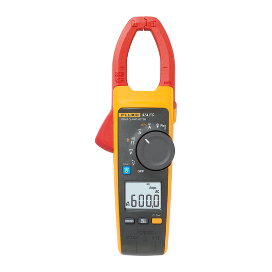
Page 13: The Meter
Clamp Meter The Meter The Meter Clamp Meter fig01.eps Figure 1. The Meter Specifications Electrical Specifications AC Current via Jaw Range 374 and 375 ........600.0 A 376............. 999.9 A Resolution ..........0.1 A Accuracy ..........2 % 5 digits (10-100 Hz) 2.5 % 5 digits (100-500 Hz) Crest Factor (50/60 Hz) ...... - Page 14 374/375/376 Calibration Manual Position Sensitivity ghn12.eps Figure 2. Position Sensitivity Distance from i2500-10 Flex i2500-18 Flex Error Optimum 0.5 in (12.7 mm) 1.4 in (35.6 mm) 0.5 % 0.8 in (20.3 mm) 2.0 in (50.8 mm) 1.0 % 1.4 in (35.6 mm) 2.5 in (63.5 mm) 2.0 % Measurement uncertainty assumes centralized primary conductor at optimum position, no external...
- Page 15 Clamp Meter Specifications DC Voltage Range 374 and 375 ........600.0 V 376 ............1000 V Resolution 374 and 375 ........0.1 V 376 ............0.1 V ( 600.0 V) 1 V ( 1000 V) Accuracy ..........1 % 5 digits mV dc Range 375 and 376........
-
Page 16: Mechanical Specifications
374/375/376 Calibration Manual Mechanical Specifications Size (L x W x H) ........246 mm x 83 m x 43 mm Weight............. 388 g Jaw Opening ........... 34 mm Flexible Current Probe Diameter .... 7.5 mm Flexible Current Probe Cable Length (head to electronics connector) .... -
Page 17: Performance Tests
Clamp Meter Performance Tests Performance Tests XWWarning To prevent possible electrical shock, fire, or personal injury, do not perform the performance test procedures unless the Product is fully assembled. The following performance tests verify the complete operation of the Product and check the accuracy of each function against the Product’s specifications. -
Page 18: Calibration Adjustment
The equipment listed in Table 3 is required for calibration adjustment. Table 3. Required Equipment Equipment Required Characteristics Recommended Model Calibrator 4.5-digit resolution Fluke 55xxA Calibrator Wired coil 50 turns 5500A/COIL Test Lead for iFlex PN 666602 Test Lead for other... -
Page 19: Adjustment Procedure
Clamp Meter Calibration Adjustment Adjustment Procedure To adjust Product calibration: 1. Turn the Product over to access the battery compartment door screw. 2. Use a flat-head screwdriver to loosen the battery compartment door screw and lift off the battery compartment door. See Figure 5. 3. - Page 20 374/375/376 Calibration Manual 5522A CALIBR ATOR ghn50.eps Figure 4. Current Calibration Setup The calibration adjustment is complete. When the adjustment is complete: 1. Remove the Power Supply. 2. Replace the batteries. 3. Reattach the battery compartment door. 4. Tighten the battery compartment door screw.
-
Page 21: Adjustment Procedure
Clamp Meter Calibration Adjustment Table 4. Adjustment Procedure Test Calibrator Output Reading (Switch Position) C-00 600 V @ 50 Hz AC Volts C-01 300 V @ 50 Hz C-02 300 V @ 100 Hz C-03 300 V @ 200 Hz C-04 300 V @ 300 Hz C-05... - Page 22 374/375/376 Calibration Manual Table 4. Adjustment Procedure (cont.) Test Calibrator Output Reading (Switch Position) C-23 8 A @ 50 Hz AC Amps C-24 3 A @ 50 Hz (with 50-turn Coil) C-25 3 A @ 100 Hz C-26 3 A @ 200 Hz C-27 3 A @ 300 Hz C-28...
-
Page 23: Maintenance
Clamp Meter Maintenance Maintenance Clean the Product WCaution To prevent possible damage to the Product or to equipment under test, do not use abrasive cleaners. They will damage the case. To clean the Product, use a cloth with a mild cleaning solution. Battery Replacement XW Warning To prevent possible explosion, fire, or personal injury, replace... -
Page 24: User Replaceable Parts
User replaceable parts are listed in Table 5. Table 5. User Replaceable Parts Fluke Part Description Number 3845988 Battery Door Assembly 3752958 Soft Case 3608883 User Manual 376756 Battery (AA 1.5V) 3782019 TL175 test leads 855742 TL75 test leads 3798105 Fluke i2500-18 Rogowski coil 3868305 Calibration Sticker...
Need help?
Do you have a question about the 374 and is the answer not in the manual?
Questions and answers