Table of Contents
Advertisement
Quick Links
Introduction
To prevent electric shock or injury, do not do the performance tests or calibration
adjustment procedures unless qualified to do so.
The information provided in this document is for the use of qualified personnel
only.
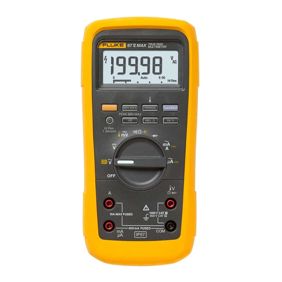
This document provides adjustment and performance test procedures for the Fluke 87V MAX
Digital Multimeter (the Meter or the Product).
See the 87V MAX Users Manual for complete operating instructions.
Contact Fluke
Fluke Corporation operates worldwide. For local contact information, go to our website:
www.fluke.com.
To register your product, or to view, print, or download the latest manual or manual supplement,
go to our website.
+1-425-446-5500
fluke-info@fluke.com
January 2020 Rev. 1, 10/24
©2020-2024 Fluke Corporation. All rights reserved.
Specifications are subject to change without notice.
All product names are trademarks of their respective companies.
Calibration Information
Warning
87V MAX
Digital Multimeter
1
Advertisement
Table of Contents

Related Manuals for Fluke 87V MAX


Summary of Contents for Fluke 87V MAX
- Page 1 The information provided in this document is for the use of qualified personnel only. This document provides adjustment and performance test procedures for the Fluke 87V MAX Digital Multimeter (the Meter or the Product). See the 87V MAX Users Manual for complete operating instructions.
-
Page 2: Safety Information
General Safety Information is in the printed Safety Information document that ships with the Product and at www.fluke.com. More specific safety information is listed where applicable. A Warning identifies hazardous conditions and procedures that are dangerous to the user. A Caution identifies conditions and procedures that can cause damage to the Product or the equipment under test. -
Page 3: Static Awareness
Digital Multimeter Basic Maintenance Static Awareness Semiconductors and integrated circuits can be damaged by electrostatic discharge during handling. This notice explains how to minimize damage to these components. 1. Understand the problem. 2. Learn the guidelines for proper handling. 3. - Page 4 87V MAX Calibration Information Fuse Test To test the fuse: 1. Put the Meter into the function. 2. Insert a test lead into the jack. 3. Place the probe tip on the other end of the test lead against the metal of the current input jack.
-
Page 5: Replace The Batteries
Digital Multimeter Basic Maintenance Replace the Batteries Replace the batteries with three AA batteries (NEDA 15A IEC LR6). Warning To prevent possible electrical shock, fire, or personal injury: Batteries contain hazardous chemicals that can cause burns or explode. If exposure ... -
Page 6: Performance Tests
87V MAX Calibration Information The 440-mA fuse is shorter than the 10-A fuse. For correct placement of each fuse, note the marking on the printed circuit board (PCA) under each fuse. 6. To replace the fuse compartment door, align the arrow on the fuse door with the arrow on the case bottom and lower the door into the fuse compartment. -
Page 7: Required Equipment
Digital Multimeter Performance Tests Required Equipment Table 1 lists the equipment required to conduct performance tests on the Meter. Table 1. Required Equipment Measurement Recommended Equipment Accuracy Function DC Volts 0 V to 1000 V0.012 % DC Current 350 A to 2 A0.05 % 0 V to 1000 V0.15 % @ 60 Hz to 20 kHz AC Volts 3 %... - Page 8 87V MAX Calibration Information Table 2. Accuracy Tests (cont.) Step Test Function Range Calibrator Output Display Reading 600 mV 150 mV, 99.95 kHz 99.93 to 99.97 AC Volts 600 mV 150 mV, 199.50 kHz 199.48 to 199.52 Frequency 0.7 V, 99.95 kHz 99.93 to 99.97...
-
Page 9: Calibration Adjustments
Digital Multimeter Calibration Adjustments Table 2. Accuracy Tests (cont.) Step Test Function Range Calibrator Output Display Reading 60 mA 33 mA, 60 Hz 32.65 to 33.35 400 mA 330 mA, 60 Hz 326.5 to 333.5 AC Milliamps 60 mA 33 mA 32.89 to 33.11 ... -
Page 10: Change The Password
87V MAX Calibration Information Calibration (CAL) Mode Pushbutton Functions The CAL mode is initiated when you hold down at power up and enter a four-digit password. acts as an ENTER key and advances through the CAL initiation and adjustment ... -
Page 11: Restore The Default Password
Digital Multimeter Calibration Adjustments Restore the Default Password If the password is forgotten, restore the default password (1234): 1. Turn the Meter Rotary Switch to OFF. 2. Remove the bottom case and bottom shield of the Meter. 3. Check the revision number on the printed circuit board (PCB). The board revision location is identified in Figure 3 Figure... - Page 12 87V MAX Calibration Information 3. As you short across the keypad button S7, turn the Rotary Switch one position clockwise. 4. Short across keypad button S11. 5. Turn the rotary switch back to its original position. The default password is now restored.
-
Page 13: Other Pushbutton Functions
Digital Multimeter Calibration Adjustments 2. Turn the Rotary Switch from OFF to as you hold down at the same time. The Meter shows 3. Short across keypad button S11 on the back of the PCB. The Meter beeps. 4. - Page 14 87V MAX Calibration Information Note After you push , wait for the step number to advance before you change the calibrator source or turn the Meter Rotary Switch. If the reference source input is not within the required range value, the Meter double beeps and does not allow completion of the step.
- Page 15 Digital Multimeter Disassemble the Meter Table 4. Calibration Adjustment Steps (cont.) Function Adjustment Step Input Value (Switch Position) C-24 60.00 mA, 60 Hz C-25 400.0 mA, 60 Hz C-26 60.00 mA dc (Amps) C-27 400.0 mA dc C-28 600.0 A, 60 Hz C-29 6000 A, 60 Hz ...
-
Page 16: How To Retain The Ip67 Rating
7. Case Screw O-ring: Torque case screws to 12 in-lbs torque. Verify that the o-rings are not sticking out of the sides of the screw head. Note To ensure your Meter meets the IP67 rating, return the Meter to a qualified Fluke Service Center. -
Page 17: Replacement Parts
Digital Multimeter Replacement Parts Replacement Parts Table 5 lists replaceable parts of the Meter that are identified in Figure Figure 5. Exploded View H1 (6) MP3 (2) BT1 (3) H2 (6) H3 (6) MP8 (2) H4 (7) H4 (7) H5 (4) MP10 MP14 MP11... - Page 18 CONTACTS FLUKE-2X-II-8007, GASKET, BATT DOOR, FLUKE 27-II 3439087 AVG AND FLUKE 28-II TRMS METERS FLUKE 89-4-8012, BATTERY CONTACT, DUAL 666435 FLUKE-2X-2-2014, FUSE ACCESS DOOR, 27-2 AVG AND 3400480 28-2 TRMS MULTIMETER FLUKE-2X-2-2015, FUSE CAP 3440546 FLUKE-2X-2-2004, CASE, BOTTOM WITHOUT BATTERY...
- Page 19 Digital Multimeter Replacement Parts Table 5. Replaceable Parts List (cont.) Item Description Part Number Qty. FLUKE-2X-2-8001, TOP SHIELD, FLUKE 27-2 AVG / MP13 3371939 FLUKE 28-2 TRMS MULTIMETER FLUKE-2X-2-8009, BACKLIGHT, FLUKE 27II / FLUKE 28II MP14 3471251 MULTIMETER FLUKE-87V-MAX-2501, MASK, LCD (PAD XFER) 87V-...
- Page 20 Lifetime Limited Warranty Each Fluke 20, 70, 80, 170, 180 and 280 Series DMM will be free from defects in material and workmanship for its lifetime. As used herein, “lifetime” is defined as seven years after Fluke discontinues manufacturing the product, but the warranty period shall be at least ten years from the date of purchase.
Need help?
Do you have a question about the 87V MAX and is the answer not in the manual?
Questions and answers