Alarm Lock Trilogy DK3000 Series Programming Instructions Manual
Alarm lock trilogy series of standalone access control systems
Hide thumbs
Also See for Trilogy DK3000 Series:
- Brochure (2 pages) ,
- Installation instructions (1 page) ,
- Datasheet (2 pages)
Table of Contents
Advertisement
Trilogy
DK3000 Series
345 Bayview Avenue
Amityville, New York 11701
Programming Instructions
For Sales and Repairs 1-800-ALA-LOCK
For Technical Service 1-800-645-9440
Publicly traded on NASDAQ
Symbol: NSSC
© ALARM LOCK 2007
WI 1119E 5/07
DK3000
DL-WINDOWS PROGRAMMING SOFTWARE
AL-IR1 PRINTER
AL-DTM
DATA TRANSFER MODULE
Alarm Lock Trilogy Series of
Standalone Access Control Systems
1
Advertisement
Table of Contents

Related Manuals for Alarm Lock Trilogy DK3000 Series


Summary of Contents for Alarm Lock Trilogy DK3000 Series
- Page 1 For Sales and Repairs 1-800-ALA-LOCK For Technical Service 1-800-645-9440 Publicly traded on NASDAQ Symbol: NSSC © ALARM LOCK 2007 WI 1119E 5/07 DK3000 DL-WINDOWS PROGRAMMING SOFTWARE AL-IR1 PRINTER AL-DTM DATA TRANSFER MODULE Alarm Lock Trilogy Series of Standalone Access Control Systems...
-
Page 2: Table Of Contents
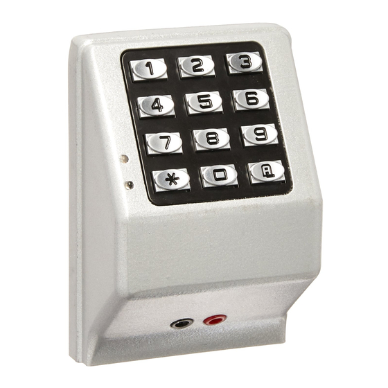
Instead of a lock, the DK3000 keypad operates main and auxiliary relays, and can be used to trigger a door strike, an electromagnetic door lock, or any other relay-activated device. Programming may be performed manually from the keypad, or from a PC using Alarm Lock's DL-Windows Software. -
Page 3: Audit Trail
• Ambush Function (see page 25, Function 66) Keypad and Computer Programming • All programming may be performed manually from the keypad, or from a PC using Alarm Lock's DL- Windows Software (see page 4) Auxiliary Relay • Can be programmed to follow the Main/Entry Relay to operate (for example) a second door •... -
Page 4: Supported Products
AL-PCI Cable An ALARM LOCK AL-PCI cable is required to communicate between your computer’s RS-232 serial com- munications port (COM 1-4) and the AL-DTM or lock. One end of the AL-PCI cable is designed to be used on a 9-pin serial Com Port. -
Page 5: Lock Design Overview
The answer lies in the advantage of SOFTWARE. Software (also known as "firmware") is not "hard" or "fixed" like hardware is. Software is "soft" -- flexible and changeable to your needs. Software exists inside your Alarm Lock™ series lock, and can be programmed (and re- programmed again and again) to suit your changing requirements. -
Page 6: Terminology Used In This Manual
Terminology Used in this Manual What is a Lock Program? What is a Programming Level? A Lock Program contains the instructions that a lock uses to per- The Programming Level defines the range of programming tasks a form its various functions. You can use the keypad to create a User is allowed to perform. - Page 7 DL-Windows is a computer program that allows you to program With many lock applications, it is convenient for large numbers of your ALARM LOCK T3 Security Lock. You do not need DL- similar Users to be grouped together. Placing Users into Groups...
-
Page 8: Programming Levels
Programming Levels The Programming Level defines the range of programming tasks as Programming Level = 4). a User is allowed to perform. The higher the Level, the more pro- Manager: Always associated with Users 4, 5, and 6. Can pro- gramming tasks the User is allowed (with Master allowing ALL gram all functions except functions relating to lock tasks). -
Page 9: Conventions Used In This Manual
Conventions Used in this Manual Enabling/Disabling Users (By User Number) Minimum Required Program Level User Number must be between 2 and 2000. Program Levels are abbreviated as follows: NOTE: Will Enable/Disable users even if the user is associated with an enabled group. Function M = Master Description... -
Page 10: Product Communication Examples
Product Communication Examples Send to lock Receive from lock If your computer does not have a serial COM port AL-PCI CABLE (DB-9 male) available, you can plug your AL-PCI2 CONNECT TO SERIAL PORT (COM 1-4) cable into a special USB to RS-232 cable. Order part PCI-USB for the USB to RS-232 cable only, or ALPCI2-U for... -
Page 11: Wiring, Power Up And Specifications
Wiring, Power Up and Specifications WIRING 4. Do not press any keys for 15 seconds. 5. After 15 seconds, the LED will flash red 6 times and 6 See the Installation Manual for detailed illustrations and beeps will sound. additional information. The lock is now ready for use. -
Page 12: Basic Wiring
BASIC WIRING: DK3000 Interfacing to an access control system to allow code access in addition to keyfob access. Auxiliary Relay is not connected. POWER SUPPLY OPTIONS WARNING Simplified Power Supply Option: Recommended Supply Option: In all cases, be sure to Transformer 12 to 24 VAC or DC Battery Backup 12 to 24V AC or DC allow for emergency exit... -
Page 13: Typical Application
TYPICAL APPLICATION: DK3000 Using a normally open push-button switch to provide passage via the door strike, and the Auxiliary Output to trigger a visual or audible device only when door is unlocked. POWER SUPPLY OPTIONS WARNING Simplified Power Supply Option: Recommended Supply Option: In all cases, be sure to Transformer 12 to 24 VAC or DC... -
Page 14: Quick Start
Quick Start First Time Start Up 1. Unpack the lock. 2. With the power disconnected, hold down the ; key for 10 seconds and release. 3. Connect the power and listen for 3 beeps. Within 5 seconds of hearing the 3 beeps, press and hold ; until beeping starts. -
Page 15: Testing The Codes Entered
Quick Start (cont’d) Delete a User Code 1. Enter Program Mode (if not in already). 2. Press ; 2 ; User Number The lock will flash a green LED and beep continuously for 6 seconds. When the red LED flashes, the User Code is deleted. 3. -
Page 16: Programming Functions Overview
Programming Functions--Overview Function 1 Change Master Code See page 17 Function 48 Enable Passage Mode See page 23 Function 2 Add/Delete/Change User Codes See page 17 Function 49 Disable Passage Mode See page 23 Function 50 Return Lock to Normal Passage See page 23 Function 3 User Disable (By User Number) -
Page 17: Programming Functions
Programming Functions USERS 1. New Master Code [ _ _ _ _ _ _ ] [ _ _ _ _ _ _ ] (User Number 1) (New Master Code) (Confirm New Master Code) • Master Code must be 6 digits-only. •... - Page 18 Programming Functions (cont'd) USERS (Continued) User Enable/Disable (By User Number) • User Number must be between 2 and 2000. NOTE: Will Enable/Disable Users even if the User is associated with an enabled Group. Use Feature 3 to disable a specific User Number and their associated User Code.
- Page 19 Programming Functions (cont'd) CLEAR FUNCTIONS 12. Clear All Schedules and Timeout Functions ; 1 2 ; 0 0 0 : Function 12 clears all programmed Schedules and all Timeout Functions. (To clear All Timeout Functions only, see Function 13 below). Function 12 will clear all of the following: All Schedule Functions 72 through 93, Timeout Functions 5, 25 through 34 and Function 47.
- Page 20 Programming Functions (cont'd) NOTE: Clear All Timeout Functions by entering Function 13. GROUPS Group Enable/Disable with Timeout (Enter Timeout, XXX Hours) (Functions 25-34 are enabled through the keypad only) • Hours must be between 1-999. Enter the functions below to Enable/Disable Groups for the amount of time entered in hours. NOTE: Only 4 Timeout Functions are allowed at any one time.
- Page 21 Programming Functions (cont'd) CLOCK SETTINGS 38. Set Date [ _ _ _ _ _ _ ] ; 3 8 (Date) • Use Month Day Year format - MMDDYY - Single digit months and days are entered with a preceding zero. •...
- Page 22 Programming Functions (cont'd) CLOCK ADJUST Clock Adjust Number of seconds to adjust (speed up/slow down) the clock each day must be be- tween 0-55 seconds. Note: Repeated use of these Functions are not "cumulative" (this means, for example, if the clock has already been set to speed up 10 seconds per day, and then is found to Clock Accuracy need an additional 10 seconds, then program 20 seconds using Function 43).
- Page 23 Programming Functions (cont'd) PERMANENT PASSAGE MODE Passage Mode Enable/Disable - Schedule will not Override • Function 48 allows passage through the door without the need for a User Code. Re-Lock using Function 49. • Programmed Schedules will not override the state of the lock using functions 48 and 49. If it is required that programmed schedules override Passage Mode, Enable/Disable Passage Mode using Functions 45/46.
- Page 24 Programming Functions (cont'd) PRINTER Hold the printer perpendicular to the Lock’s infrared LED as shown in Figure 1 and Figure 2. If the printer has been idle for some time, press the paper feed button to wake up the printer. Infrared Infrared Infrared...
- Page 25 Programming Functions (cont'd) 59. Reserved LOCKOUT [ _ ] 60. Number of Attempts Before Lockout ; 6 0 (Number of Attempts) Used with Function 61 • Number of attempts before lockout must be 1-9 attempts. • The number of attempts is reduced by half every time the keypad is locked out without a successful code entry (default is 6 attempts).
-
Page 26: System Options
Programming Functions (cont'd) SYSTEM FEATURES [ _ _ ] ; 6 7 67. Add System Features (Event Number) • Aux Relay Features (12-24. Reserved) Use Function 67 to program one or more lock events and the Aux Relay will energize when the programmed event(s) listed below occurs. -
Page 27: Enter Key
Programming Functions (cont'd) ENTER KEY Enter Key • When this function is enabled, the User must press after any valid User Code entry. Therefore, this Function allows User Codes to be subsets of other User Codes. Examples: 1 2 3 : can be a valid user code; 1 2 3 4 : a valid user code within the same lock. - Page 28 Programming Functions (cont'd) QUICK SCHEDULES Quick Schedules - Enable Group For your convenience, your lock comes pre-programmed with Quick Schedules, which, when programmed, enable Groups for popular blocks of time. Group members will be enabled during the blocks of time defined below, but will still need to enter their User Codes into the keypad to unlock the lock.
-
Page 29: Control Panel
Programming Functions (cont'd) SCHEDULES GROUP 1 ACTIVATED Scheduled Relay Activation (Group 1 Activated) Functions 90 and 91 allow you to set up a window of time where if any Group 1 User Code is entered within this window, the relay will be activated for 2 seconds. This relay is for use with a Control Panel that has a key switch disarm option. For additional information, see Group 1 Activated Features on page 31. - Page 30 Programming Functions (cont'd) Scheduled Group 4 Enable (Group 1 Activated) Functions 92 and 93 allow you to set up a window of time where if any Group 1 User Code is entered within this window, Group 4 members will be enabled. (Group 4 members will still need to enter their User Codes to enter). For additional information, see Group 1 Activated Features on page 31.
-
Page 31: Groups And Scheduled Group 1 Examples
The following examples detail the more advanced features of the DK series locks. Although all features and device functions can be programmed using the lock keypad, when programming becomes more complex you may find it easier to use DL-Windows software to program your Alarm Lock security lock. - Page 32 Groups and Scheduled Group 1 Examples (cont'd.) Functions 90/91: Use Function 90 and 91 (see page 29) to create a window of time where if any Group 1 User Code is entered within the programmed window, a relay will be activated for 2 seconds. The relay can be configured to disarm a burglary control panel. See page 29. 1.
-
Page 33: Programming Record Sheet
Default Values are shown in parentheses. Function Number(s) Function Name Programming 43/44 Clock Adjust 0-55 Seconds 52/53/54 Pass Time (3 sec) 10 sec 15 sec Set Lockout Attempts 1-9 Attempts Set Lockout Time 1-60 seconds 64/65 Remote Input Momentary (Enable) Disable Ambush Code 00-99... -
Page 34: User Code Record Sheet
User Number User Code Group User Name (1-2000) (3-6 digits) Association Note: For a complete list of user codes, obtain a printout from either the remote printer (Program Function 56) or using the DL-WINDOWS Software. -
Page 35: Schedule Record Sheet
Day(s) Up to 500 scheduled functions can be programmed (Up to only 150 using AL-DTM2). For Day Enter : 1 = Sunday, 2 = Monday, 3 = Tuesday, 4 = Wednesday Function Number Time Function Name 5 = Thursday, 6 = Friday, 7 = Saturday, 8 = Monday through Friday, 9 = Saturday and Sunday, 0 = All days of the week Enter time of day in 24-hour format (00:00- 23:59) -
Page 36: Glossary
Glossary • ACCESS = Entry into a restricted area. SERVICE CODE = User 300 User Code. Allows only one entry, then needs to be re-enabled by the User 297 User Code to regain access. AMBUSH = A special Code entered at the keypad when the User is forced to unlock a device. - Page 37 Glossary (cont'd) REMOTE INPUT = Entry into a restricted area, by pressing a button connected to the REMOTE INPUT WIRES (White and White) by • GROUP 1 ENABLES GROUP 4 USERS = A Group 1 USER CODE someone on the other side of the door. entry during a predefined schedule will allow access to Group 4 Users.
- Page 38 NOTES...
- Page 39 NOTES...
-
Page 40: Warranty
ALARM LOCK is not an insurer of either the property or safety of the user's family or employees, and limits its liability for any loss or damage including incidental or consequential damages to ALARM LOCK's original selling price of the product regardless of the cause of such loss or damage.
Need help?
Do you have a question about the Trilogy DK3000 Series and is the answer not in the manual?
Questions and answers
I have an RV pk bathhouse. I have the master code set up and time, date etc. I don’t need the residents to have a code. I just need to have the door automatically unlock at 6 am and lock at 9:30 pm. I can’t figure it out. Thanks