Table of Contents
Advertisement
Quick Links
Advertisement
Table of Contents

Related Manuals for Gigabyte GS-A21S-RH


Summary of Contents for Gigabyte GS-A21S-RH
- Page 1 User`s Manual GS-A21S-RH...
- Page 2 GS-A21S-RH User’s Manual Rev. 1.0 25A08G-0A210-C00...
-
Page 3: Table Of Contents
Installing Mini PCI Express Card ................... 20 Stealthed USB Device Door ................... 21 Specifications ..................22 Specifications ........................22 Appendix A Cleaning and Maintenance ..........23 Taking Care of Your GS-A21S-RH ................. 23 Cleaning and Maintenance ..................... 23 Appendix B Service Center ..............24... -
Page 4: Safety, Care And Regulatory Information
GS-A21S-RH User’s Manual Safety, Care and Regulatory Information Important safety information Read and follow all instructions marked on the product and in the documentation before you operate your system. Retain all safety and operating instructions for future use. * The product should be operated only from the type of power source indicated on the rating label. - Page 5 GS-A21S-RH User's Manual * To reduce the risk of fire, use only No. 26 AWG or larger telecommunications line cord. * Do not plug a modem or telephone cable into the network interface controller (NIC) receptacle. * Disconnect the modem cable before opening a product enclosure, touching or installing internal components, or touching an uninsulated modem cable or jack.
- Page 6 GS-A21S-RH User’s Manual Your telephone company may make changes in its facilities, equipment, operations, or procedures that could affect proper operation of your equipment. If they do, you will be notified in advance to give you an opportunity to maintain uninterrupted telephone service.
- Page 7 / for European users only / WEEE-Consumer Notice: The GIGABYTE product you have purchased is subject to Directive 2002/96/EC of the European Parliament and the Council of the European Union on waste electrical and electronic equipment (WEEE) and, in jurisdictions adopting that Directive, is marked as being put on the market after August 13, 2005, and should not be disposed of as unsorted municipal waste.
-
Page 8: Getting Started
GS-A21S-RH User’s Manual Getting Started Packing Checklist Carefully unpack the GS-A21S-RH and check the following items are included: GS-A21S-RH System x 1 Adapter x 1 Cooling fan x 1 (for Barebone only) Remote Control (optional) Two AA Batteries for Remote Control (optional) User’s Manual &... -
Page 9: Features At A Glance
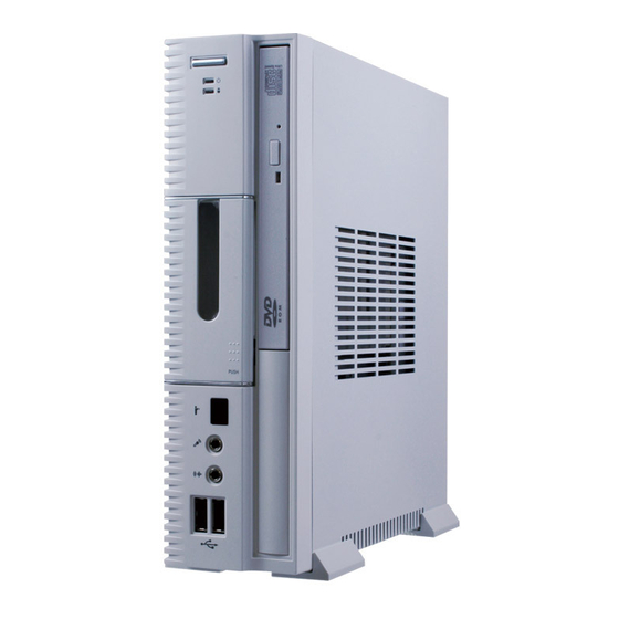
GS-A21S-RH User's Manual System Appreance Features at a Glance Front View of GS-A21S-RH Power Button Power and HDD LED Optical Drive Indicator Stealthed USB Port Door (User can plug in USB device such as Wireless LAN and RF keyboard receiver) -
Page 10: Rear View Of Gs-A21S-Rh
GS-A21S-RH User’s Manual Rear View of GS-A21S-RH Power Cord SPDIF YPbPr HDMI Port Pull Handle DVI-D Port VGA Port USB Ports LAN Port Audio jack Port lock Port... -
Page 11: System Hardware Installation
GS-A21S-RH User's Manual System Hardware Installation Please observe the safety information in chapter “Important Safety Information” Do not expose the system to extreme environmental conditions. Protect it from dust, humidity, and heat. Chassis Removal and Installation Step 1 Remove the screw from the bottom of the chassis. -
Page 12: Installing Hard Disk Drive
GS-A21S-RH User’s Manual Installing Hard Disk Drive Warning Please turn off the computer and unplug its power cord before removing and installing hard drives. Step 1 Place HDD on the plate. Tighten HDD with four screws. Step 2 Connect HDD power connector and cable to the HDD. - Page 13 GS-A21S-RH User's Manual Step 3 Tighten the HDD rack to the chassis with 4 screws.
-
Page 14: Installing Optical Disk Drive
GS-A21S-RH User’s Manual Installing Optical Disk Drive Step 1. Remove the front cover from the system. See the arrow direction below. Step 2. Remove the two screws and ODD dummy door. Place the front cover back to the system. - Page 15 GS-A21S-RH User's Manual Step 3 Install USB to IDE Card to the optical disk drive, secure the USB to IDE Card with a screw. Note that use the longer screw in the Screws Pack.. M2*2.5L M2*4.5L (for ODD bracket) (for USB to IDE Card)
- Page 16 GS-A21S-RH User’s Manual Step 4 Place ODD bracket on the Optical Disk Drive. Secure the bracket with screws. Note that use the shorter screws in the Screws Pack.. Step 5. Place the rack back and tighten the rack to the chassis. Connect ODD cable.
-
Page 17: Installing Cpu And Cooling Fan
GS-A21S-RH User's Manual Installing CPU and Cooling Fan Step 1. The processor socket come with a screw to secure the processor. Insert the CPU into the socket by making sure the notch on the corner of the CPU corresponds with the notch on the inside of the socket. Once the processor has slide into the socket, lock the screw. - Page 18 GS-A21S-RH User’s Manual Step 3. Connect the power to the SYS_FAN power cable connector.
-
Page 19: Installing Memory
GS-A21S-RH User's Manual Installing Memory Step 1. Insert the DIMM memory module vertically into the DIMM slot, and push it down. Step 2. Close the plastic clip at both edges of the DIMM slots to lock the DIMM module. -
Page 20: Installing Mini Pci Card
GS-A21S-RH User’s Manual Installing Mini PCI Card Step 1 Align the connector edge of the mini PCI card with the connector slot. Insert the mini PCI card at 45 degree angle and press it down until it locks inderneath retaining clip. -
Page 21: Installing Mini Pci Express Card
GS-A21S-RH User's Manual Installing Mini PCI Express Card Step 1 Align the connector edge of the mini PCI -E card with the connector slot. Insert the mini PCI-E card at 45 degree angle and press it down until it locks inderneath retaining clip. -
Page 22: Stealthed Usb Device Door
GS-A21S-RH User’s Manual Stealthed USB Device Door GS-A21S-RH stealth bay cover provides superior style and visual appeal. User can easily plug in USB device such as mp3 player, wireless LAN, or wireless RF keyboard receiver. Device can be hidden from view when it is in use. This provides a neat and functional finish. -
Page 23: Specifications
GS-A21S-RH User's Manual Specifications Specifications Board GA-6KIEH2-RH Intel Core 2 Duo (Socket P) CPU Series DRAM 2 DDR2 DIMM slots SATA 2.5” HDD Dimemsions 213 (D) x 64 (W) x 234 (H) mm Power Rating 90W Adapter 100-240V~1.3A 50-60Hz Output 19V-4.74A Operating 0 Front I/O USB 2.0 Port x 3 (Including inside the front cover) /... -
Page 24: Appendix A Cleaning And Maintenance
The openings on the enclosure are for air convection hence your notebook computer can be protected from overheating. DO NOT COVER THE OPENINGS. Do not expose GS-A21S-RH to direct sunlight. Do not place it near sources of heat, such as a radiator. -
Page 25: Appendix B Service Center
GS-A21S-RH User's Manual Appendix B Service Center In order to serve you better, we have reorganized our Technical Support Zone Please Visit our web site GIGABYTE Technical Service Zone for further technical support. Taiwan ( Headquarters ) GIGA-BYTE TECHNOLOGY CO., LTD.
Need help?
Do you have a question about the GS-A21S-RH and is the answer not in the manual?
Questions and answers