Table of Contents
Advertisement
Quick Links
ETHERNET SWITCH MODULE
(3E02-04/3E05-04/3E07-04/3E08-04
SEGMENT 1
SEGMENT 2
LINK RX
LINK RX
COL TX
COL TX
OFFLINE
X
X
SEGMENT 1
SEGMENT 2
RX
RX
TX
TX
OFFLINE
AND 3E02-08-ATX)
USER GUIDE
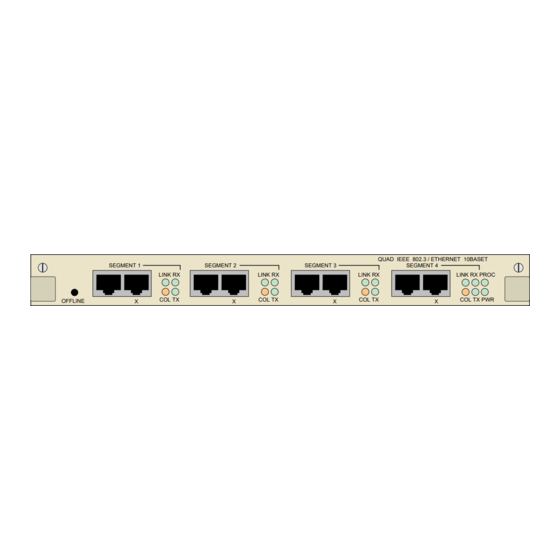
QUAD IEEE 802.3 / ETHERNET 10BASET
SEGMENT 3
SEGMENT 4
LINK RX
LINK RX PROC
COL TX
COL TX PWR
X
X
QUAD IEEE 802.3 / ETHERNET 10BASE2
SEGMENT 3
SEGMENT 4
RX
RX
PROC
TX
TX
PWR
SEGMENT
1X
2X
3X
4X
5X
OFFLINE
SEGMENT 1
SEGMENT 2
RX
RESET
TX
SEGMENT 1
SEGMENT 2
LINK RX
COL TX
OFFLINE
RX
TX
RX
OCTAL IEEE 802.3 / ETHERNET 10BASE-T
6X
7X
8X
LINK
PROC
ACT
COL
1
2
3
4
5
6
7
8
PWR
QUAD IEEE 802.3 / ETHERNET AUI
SEGMENT 3
SEGMENT 4
RX
RX
RX
TX
TX
TX
QUAD IEEE 802.3 / ETHERNET 10BASE-FL
SEGMENT 3
SEGMENT 4
LINK RX
LINK RX
LINK RX
COL TX
COL TX
COL TX
TX
RX
TX
RX
TX
PROC
PWR
PROC
PWR
Advertisement
Table of Contents
Troubleshooting

Subscribe to Our Youtube Channel
Related Manuals for Cabletron Systems 3E02-04


Summary of Contents for Cabletron Systems 3E02-04
- Page 1 ETHERNET SWITCH MODULE (3E02-04/3E05-04/3E07-04/3E08-04 AND 3E02-08-ATX) USER GUIDE QUAD IEEE 802.3 / ETHERNET 10BASET QUAD IEEE 802.3 / ETHERNET AUI SEGMENT 1 SEGMENT 2 SEGMENT 3 SEGMENT 4 SEGMENT 1 SEGMENT 2 SEGMENT 3 SEGMENT 4 LINK RX LINK RX LINK RX LINK RX PROC PROC...
- Page 3 NOTICE Cabletron Systems reserves the right to make changes in specifications and other information contained in this document without prior notice. The reader should in all cases consult Cabletron Systems to determine whether any such changes have been made. The hardware, firmware, or software described in this manual is subject to change without notice. IN NO EVENT SHALL CABLETRON SYSTEMS BE LIABLE FOR ANY INCIDENTAL, INDIRECT, SPECIAL, OR CONSEQUENTIAL DAMAGES WHATSOEVER (INCLUDING BUT NOT LIMITED TO LOST PROFITS) ARISING OUT OF OR RELATED TO THIS MANUAL OR...
-
Page 4: Fcc Notice
Notice FCC NOTICE This device complies with Part 15 of the FCC rules. Operation is subject to the following two conditions: (1) this device may not cause harmful interference, and (2) this device must accept any interference received, including interference that may cause undesired operation. NOTE: This equipment has been tested and found to comply with the limits for a Class A digital device, pursuant to Part 15 of the FCC rules. - Page 5 Notice CABLETRON SYSTEMS, INC. PROGRAM LICENSE AGREEMENT IMPORTANT: Before utilizing this product, carefully read this License Agreement. This document is an agreement between you, the end user, and Cabletron Systems, Inc. (“Cabletron”) that sets forth your rights and obligations with respect to the Cabletron software program (the “Program”) contained in this package.
- Page 6 Notice UNITED STATES GOVERNMENT RESTRICTED RIGHTS The enclosed product (a) was developed solely at private expense; (b) contains “restricted computer software” submitted with restricted rights in accordance with Section 52227-19 (a) through (d) of the Commercial Computer Software - Restricted Rights Clause and its successors, and (c) in all respects is proprietary data belonging to Cabletron and/or its suppliers.
-
Page 7: Table Of Contents
CONTENTS CHAPTER 1 INTRODUCTION Document Conventions ............... 1-2 Related Manuals................1-3 Getting Help................. 1-3 General Description..............1-4 3E02-04 Ethernet Switch Module ..........1-5 1.5.1 Connectors ..............1-6 1.5.2 LEDs ................1-6 1.5.3 Offline Button ..............1-6 3E07-04 Ethernet Switch Module ..........1-6 1.6.1 Connectors .............. - Page 8 Contents CHAPTER 3 CONFIGURING Introduction ..................3-1 Connecting the Local Console Manager........3-2 LCM Commands ................3-2 CHAPTER 4 MONITORING Displaying Port Status..............4-1 4.1.1 Status Command.............4-1 CHAPTER 5 DIAGNOSTICS AND TROUBLESHOOTING Power-up Diagnostics ..............5-1 5.1.1 Power-up Tests ...............5-1 5.1.2 Power-Up Results ............5-1 Operational Diagnostics ...............5-3 5.2.1 Diagnostic Results............5-4 Troubleshooting ................5-4...
-
Page 9: Chapter 1 Introduction
CHAPTER 1 INTRODUCTION This manual is for system administrators responsible for configuring, monitoring and maintaining the ATX. It should be used with the ATX User Guide and the ATX MIB Reference Guide. The contents of each chapter are described below. •... -
Page 10: Document Conventions
Chapter 1: Introduction 1.1 DOCUMENT CONVENTIONS The following conventions are used in presenting information in this manual: Commands, prompts, and information displayed by the computer appear in Courier typeface: Current Number of Station Addresses: 5 Current Number of Learned Addresses: 133 Number of Defined Filters: 4 Information that you enter appears in Courier bold typeface: ATX >status... -
Page 11: Related Manuals
Related Manuals 1.2 RELATED MANUALS You may need to refer to the following documentation when you are using the Ethernet module: • ATX User Guide – contains installation and configuration instructions for the ATX. • ATX MIB Reference Guide – describes the use of Cabletron’s enterprise MIB. -
Page 12: General Description
Chapter 1: Introduction 1.4 GENERAL DESCRIPTION Cabletron Systems Ethernet Switch Modules connect the ATX to a maximum of four individual Ethernet IEEE 802.3 LANs. The Ethernet Switch Module (3E02-08-ATX) connects to a maximum of eight Ethernet IEEE 802.3 LANs. Both module types enable connectivity to FDDI, Token Ring, and Ethernet networks, and can be configured to support Transparent Spanning Tree, Source Routing, or Source Routing Transparent Bridging on each of the ports. -
Page 13: 3E02-04 Ethernet Switch Module
3E02-04 Ethernet Switch Module Each module provides connectivity to the multiple LANs. Since packets are bridged/routed across Ethernet Switch Modules only when it is necessary to reach the end device, each four port module can support four distinct 10 Mbps LANs, while the eight port module supports eight distinct 10 Mbps LANs. -
Page 14: Connectors
Chapter 1: Introduction 1.5.1 Connectors The 3E02-04 includes eight 8-pin RJ45 ports for attachment directly to the network through UTP cabling. The ATX power supply provides the power for the module. An internal receive/transmit pair crossover is provided in the NOTE second connector (far right, marked with an X) on each port. -
Page 15: 3E08-04 Ethernet Switch Module
3E08-04 Ethernet Switch Module 1.6.1 Connectors The 3E07-04 includes four pairs of BNC barrel connectors for thin coaxial cabling. Each of the four segments provides an internal BNC T-connector, therefore an external T-connector is not required. The ATX power supply provides the power for the module. 1.6.2 LEDs The 3E07-04 contains a total of 10 green LEDs labeled RX and TX for... -
Page 16: 3E05-04 Ethernet Switch Module
Chapter 1: Introduction 1.7.1 Connectors The 3E08-04 includes four pairs of fiber optic ST connectors for fiber optic cabling. Receive (RX) and transmit (TX) connectors are clearly marked on the front panel of the module. The ATX power supply provides the power for the module. -
Page 17: 3E02-08-Atx Ethernet Switch Module
3E02-08-ATX Ethernet Switch Module 1.8.2 LEDs The 3E05-04 contains a total of 10 green LEDs labeled RX and TX for each segment, plus PROC and PWR for the module. The LEDs are described in Chapter 5 of this manual. 1.8.3 Offline Button Use the offline button before swapping the module, to take it offline until the replacement is installed. -
Page 18: Leds
Chapter 1: Introduction 1.9.2 LEDs The 3E02-08-ATX contains a total of 26 green LEDs labeled LINK, ACT, COL for each segment, plus PROC and PWR for the module. The LEDs are described in Chapter 5 of this manual. 1.9.3 Offline Button Use the offline button before swapping the module, to take it offline until the replacement is installed. -
Page 19: Chapter 2 Connecting To The Network
CHAPTER 2 CONNECTING TO THE NETWORK 2.1 INTRODUCTION This chapter provides reference material and instructions for a network administrator configuring the Ethernet Switch Modules. For instructions on adding a module to the ATX, see Chapter 6, Adding/Swapping Modules. 2.2 POWER-UP LED SEQUENCE Power-up the ATX and observe the LED sequence. -
Page 20: Connecting To A Network
Chapter 2: Connecting to the Network The power-up LED sequence for an Ethernet Switch Module not attached to a network is as follows: 1. All LEDs flash. 2. The PWR LED remains on, and the TX and RX LEDs flash. 3. -
Page 21: Connecting The 3E02-04 Ethernet Switch Module
Connecting to a Network 2.3.1 Connecting the 3E02-04 Ethernet Switch Module You can connect each of the four 10BASE-T ports on the 3E02-04 to a 10BASE-T port on a device such as a workstation, server, hub, etc. using unshielded twisted pair wiring. The second RJ45 connector (far right, marked with an X) for each port on the 3E02-04 provide internal crossover. -
Page 22: Connecting The 3E08-04 Ethernet Switch Module
Chapter 2: Connecting to the Network You do not need to attach terminators to unattached segments. NOTE QUAD IEEE 802.3 / ETHERNET 10BASE2 SEGMENT 1 SEGMENT 2 SEGMENT 3 SEGMENT 4 PROC OFFLINE Figure 2-2 Connecting the 3E07-04 2.3.3 Connecting the 3E08-04 Ethernet Switch Module You can connect each of the four pairs of ST fiber ports on the 3E08-04 to a 10BASE-FL port on a device such as a hub, etc. -
Page 23: Connecting The 3E05-04 Ethernet Switch Module
Connecting to a Network 2.3.4 Connecting the 3E05-04 Ethernet Switch Module You can connect each of the four AUI connectors on the 3E05-04 to an Ethernet network. To connect the 3E05-04 module to a thick coax network, you must use an AUI drop cable and a tap-type transceiver: 1. -
Page 24: Connecting The 3E02-08-Atx Ethernet Switch Module
Chapter 2: Connecting to the Network 2.3.5 Connecting the 3E02-08-ATX Ethernet Switch Module You can connect each of the eight ports on the 3E02-08-ATX to a 10BASE-T port on a device such as a workstation, server, hub, etc. using UTP wiring. The RJ45 ports on the 3E02-08-ATX provide internal crossover, which means that, depending on whether crossover is provided on the device you’re connecting to, you can use either crossover or straight-through UTP cable to connect a device to a port. -
Page 25: Chapter 3 Configuring
CHAPTER 3 CONFIGURING 3.1 INTRODUCTION You can configure the Ethernet Switch Modules using the following tools: • Local Console Manager (LCM) – allows you to monitor, manage, and configure your ATX through an out-of-band RS-232 connection • SPECTRUM Element Manager or the full SPECTRUM Enterprise network management platform •... -
Page 26: Connecting The Local Console Manager
Chapter 3: Configuring maintained in non-volatile memory and are saved across power cycles. Filtering information is covered in the ATX User Guide. 3.2 CONNECTING THE LOCAL CONSOLE MANAGER Connect the Local Console Manager (LCM) to the ATX. Refer to Chapter 2, Connecting to the Network, of the ATX User Guide for specific instructions. -
Page 27: Monitoring
CHAPTER 4 MONITORING 4.1 DISPLAYING PORT STATUS Using LCM, you can obtain the status of ports by typing status for the appropriate port. A sample display is shown below. 4.1.1 Status Command ATX >status 2 Port 2 (1st port on module 3) status Type: Ethernet/802.3 CSMA/CD Bridging: Transparent/Translating Routing: IP Routing RIP... - Page 28 Chapter 4: Monitoring • Spanning Tree - the port’s Spanning Tree state, which could be any one of the following states: Blocking - The port is not currently the designated port to a LAN and is therefore not forwarding any packets. (This means there is another route to that LAN and, since the Spanning Tree protocol does not allow simultaneous redundant paths, this port is blocked.
- Page 29 Displaying Port Status • Total Collisions - number of collisions during packet transmissions. • Excess Collisions - number of packet transmissions that were aborted due to 16 collisions (usually a transceiver problem). • RX FCS/Align Errs - number of times a received packet was discarded due to a bad checksum or Frame Alignment error.
- Page 30 Chapter 4: Monitoring Page 4-4 Ethernet Switch Module User Guide...
-
Page 31: Chapter 5 Diagnostics And Troubleshooting
CHAPTER 5 DIAGNOSTICS AND TROUBLESHOOTING 5.1 POWER-UP DIAGNOSTICS Built-in diagnostic capabilities for the Ethernet Switch Modules include: • Power-up diagnostics, which are run every time an Ethernet Switch Module is brought online. • Front panel status LEDs. • Local and remote loopback tests. •... - Page 32 Chapter 5: Diagnostics and Troubleshooting Table 5-1 Meaning of 3E05-04 LED Indicators Meaning Ethernet port is receiving data (LED flashes) Ethernet port is transmitting data (LED flashes) PROC Processor is ready for operation POWER Module hardware is receiving power Table 5-2 Meaning of 3E07-04 LED Indicators Meaning 10BASE-2 port is receiving data (LED flashes) 10BASE-2 port is transmitting data (LED flashes)
-
Page 33: Operational Diagnostics
Operational Diagnostics Table 5-4 Meaning of 3E02-04 LED Indicators Meaning Receiver and transmitter active at the same time on 10BASE-T port and when port enters jabber state (LED flashes) 10BASE-T port is connected to another device by a cable; both cable and port are working correctly (LED is turned on) 10BASE-T port is receiving data (LED flashes) 10BASE-T port is transmitting data (LED flashes) -
Page 34: Diagnostic Results
Chapter 5: Diagnostics and Troubleshooting During a remote loopback test, the port is in normal operation, sending and receiving packets to its network. The ATX generates loopback packets which are sent out of the port to a particular destination device on the port’s network. -
Page 35: Connectivity Problems
Troubleshooting b. Remove the interface module by unscrewing the two retaining screws on the module’s front panel. Pull the module out using the “ears” on the front panel. c. Carefully but firmly press down on all socketed components. d. Re-install the module. Make sure the module is properly seated and tighten the retaining screws. - Page 36 Chapter 5: Diagnostics and Troubleshooting Page 5-6 Ethernet Switch Module User Guide...
-
Page 37: Chapter 6 Adding/Swapping Modules
CHAPTER 6 ADDING/SWAPPING MODULES Once you have received your ATX, you may want to add a new module to expand your network bandwidth, replace a module with a module of a different type, or swap a module with another module of the same type. If you are: •... -
Page 38: Swapping An Ethernet Switch Module
Chapter 6: Adding/Swapping Modules 4. Remove the installed interface module by pulling gently but firmly on the ears at the ends of the module’s front panel. 5. Gently slide the Ethernet switch module into the plastic guides in the module slot until it is completely inserted. Push the module firmly into place, as far as it will go, to fully engage the connectors at the back of the module with the backplane at the rear of the ATX chassis. - Page 39 Swapping An Ethernet Switch Module 7. Tighten the screws on each side of the module’s front panel. 8. If you took the original module offline by pressing the OFFLINE button, the new Ethernet Switch Module will automatically come back on line when it is inserted in the slot. If you used the LCM command to take the original module offline...
- Page 40 Chapter 6: Adding/Swapping Modules Page 6-4 Ethernet Switch Module User Guide...
-
Page 41: Technical Specifications
APPENDIX A TECHNICAL SPECIFICATIONS Standards Compliance • Twisted pair Ethernet • Thin Coax Ethernet • Fiber Optic Ethernet • Ethernet Version 2 • IEEE 802.3, 10BASE-T, 10BASE2, 10BASE-FL Protocol Translations • TCP/IP • • AppleTalk Dimensions 30.99 cm (12.2 in.) Length Width 24.13 cm (9.5 in.) -
Page 42: Appendix Atechnical Specifications
Appendix A: Technical Specifications Environmental Requirements Operating temperature 5˚ C to 40˚ C (41˚ F to 104˚ F) Storage temperature -30˚ C to 90˚ C (-22˚ F to 194˚ F) Relative humidity 0% to 95%, non-condensing Connectors 3E02-04 RJ45 for UTP 3E07-04 BNC for Thin Coaxial Cable 3E08-04... - Page 43 Appendix A: Technical Specifications Certifications Safety UL 1950, CSA C22.2 950, EN60950 and IEC 950 Emission FCC Part 15 Class A, EN55022 Class A, and VCCI Class I Immunity EN50082-1 Ethernet Switch Module User Guide Page A-3...
- Page 44 Appendix A: Technical Specifications Page A-4 Ethernet Switch Module User Guide...
-
Page 45: Appendix Bcables
APPENDIX B CABLES B.1 TYPES/CONNECTORS Table B-1 Cable Types and Connectors Cable Type Male Connector 100 Ohm UTP, Unshielded 22 - 26 AWG 8-pin RJ45 Twisted Pair 0.4 - 0.6 mm, 2 pairs External Transceiver Drop 15-pin DB15, AUI Thick Coaxial 50 Ohm Coax N-Type Cable... - Page 46 Appendix B: Cables Table B-3 AUI Cable Specifications Type External Transceiver Drop Max. Drop Cable Length 165 ft (50 m) Min. Drop Cable Length None Max. Number of Attachments Table B-4 Thick Coax Cable Specifications Type 50 Ohm Coax Max. Cable Segment Length 1640 ft (500 m) Min.
-
Page 47: 10Base-T Pin Assignments
10BASE-T Pin Assignments B.3 10BASE-T PIN ASSIGNMENTS An Ethernet cable link requires the use of two pairs of a multi-pair cable. While a cable containing only two pairs of wire can be used, it is more common to use four-pair cabling for 10BASE-T links. The jacket of each wire in a four-pair cable will have an overall color;... -
Page 48: Crossover Wiring
Appendix B: Cables Table B-7 RJ45 Crossover Pin Assignments RJ45 Pin Assignment Tx– Rx– *The “+” and “–” signs are used to represent the polarity of the two wires that make up each wire pair. B.3.1 Crossover Wiring Two Ethernet 10BASE-T devices can communicate only if the transmitter on one device is connected to the receiver on the other device. -
Page 49: Straight-Through Wiring
AUI Pin Assignments B.3.2 Straight-Through Wiring If the UTP link segment is to join two ports and only one of the ports has an internal crossover, the two pairs of wires must be straight-through, as shown below. Table B-9 Straight-Through RJ45 Pin Assignments Device 1 (Tx+) 3 (Tx+) -
Page 50: - 4 - 3 Rule
Appendix B: Cables Table B-10 AUI Pin Assignments (Continued) Circuit Signal Name Voltage Shield Protective Ground Shell (Conductive Shell) Voltage Plus (VP) and Voltage Common (VC) use a single NOTE twisted-pair in the AUI cable. B.5 5 - 4 - 3 RULE Between any two nodes (i.e., PCs or other stations) on the network, there may be: •... -
Page 51: Definitions
5 - 4 - 3 Rule B.5.1 Definitions Backbone A coax segment with hubs, possibly file servers. Cascade A method of interconnecting hubs using their ports rather than their stacking connectors. Link Segment A length of twisted-pair or fiber cable joining a pair of devices in a star topology (e.g., two hubs or a hub and a station). - Page 52 Appendix B: Cables Page B-8 Ethernet Switch Module User Guide...
- Page 53 INDEX Adding modules 6-1 LEDs diagnostic 5-1 power up sequence 2-1 types 1-6 to 1-10 Bridging domains A-2 Module versions 1-4 Cabling. See wiring Certifications A-3 Configuration tools 3-1 Pin assignments Connectors A-2 AUI B-5 RJ45 crossover B-4 Protocol translations A-1 Definitions B-7 Diagnostics LED 5-1...
- Page 54 Index Index-2 Ethernet Switch Module User Guide...
Need help?
Do you have a question about the 3E02-04 and is the answer not in the manual?
Questions and answers