Table of Contents
Advertisement
Quick Links
TJERNLUND PRODUCTS, INC.
1601 Ninth Street • White Bear Lake, MN 55110-6794
PHONE (800) 255-4208 • (651) 426-2993 • FAX (651) 426-9547
Visit our web site • www.tjernlund.com
MODULATING PRESSURE CONTROL
INSTALLATION INSTRUCTIONS
!
Recognize this symbol as an indication of important Safety Information!
OWNER INSTRUCTIONS, DO NOT DESTROY
WARNING
!
THESE INSTRUCTIONS ARE INTENDED AS AN AID TO QUALIFIED, LICENSED
SERVICE PERSONNEL FOR PROPER INSTALLATION, ADJUSTMENT AND
OPERATION OF THIS PRODUCT. READ THESE INSTRUCTIONS THOROUGHLY
BEFORE ATTEMPTING INSTALLATION OR OPERATION. FAILURE TO FOLLOW
THESE INSTRUCTIONS MAY RESULT IN IMPROPER INSTALLATION, ADJUST-
MENT, SERVICE OR MAINTENANCE POSSIBLY RESULTING IN FIRE, ELECTRI-
CAL SHOCK, CARBON MONOXIDE POISONING, EXPLOSION, PERSONAL
INJURY OR PROPERTY DAMAGE.
DO NOT DESTROY. PLEASE READ CAREFULLY AND
KEEP IN A SAFE PLACE FOR FUTURE REFERENCE.
Copyright © 2018, Tjernlund Products, Inc. All rights reserved
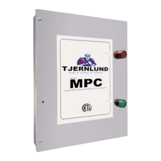
MODEL MPC
REV 0618
P/N 8504251
Advertisement
Table of Contents

Related Manuals for TJERNLUND MPC


Summary of Contents for TJERNLUND MPC
- Page 1 MENT, SERVICE OR MAINTENANCE POSSIBLY RESULTING IN FIRE, ELECTRI- CAL SHOCK, CARBON MONOXIDE POISONING, EXPLOSION, PERSONAL INJURY OR PROPERTY DAMAGE. DO NOT DESTROY. PLEASE READ CAREFULLY AND KEEP IN A SAFE PLACE FOR FUTURE REFERENCE. Copyright © 2018, Tjernlund Products, Inc. All rights reserved P/N 8504251...
-
Page 2: Table Of Contents
122 o F (50 o C) or 85% relative humidity. 3. The maximum wire distance from the Control to a VFD or ECM Exhaust Fan Motor is 300 feet. Install the MPC as close to the pressure sampling point as possible to avoid delayed response to pressure changes. Do not exceed a sampling tube length of 15 feet. -
Page 3: Sample And Reference Pressure Connections
Negative (Port Open) Recommendations based on MPC Control being installed in the same room as the sample location. If the MPC is installed in an adjacent space, pneumatic connections must be made to the open Pressure Ports that are indicated above. - Page 4 FIGURE A MULTIPLE DRYERS JOINED IN A COMMON HORIZONTAL DUCT IF POSSIBLE, THE SENSING TUBE SHOULD IF POSSIBLE, THE SENSING TUBE SHOULD The sensing tube should be installed in the vent cap of a tee or at the rear of a com- BE LOCATED ONE MAINIFOLD PIPE DIAMETER BE LOCATED TWICE THE MANIFOLD DIAMETER BEHIND THE DRYER FURTHEST FROM INDUCER...
- Page 5 Reference Pressure Sensor includes a decorative cover, sampling tube and fittings may be used in conjunction with the MPC Pressure Control. It reduces the effects of air movement on the sampling tube and provides a finished look. PESSURE SENSING TUBE INSTALLATION 1.
-
Page 6: Wiring
U.S. or CSA C22.1-12 Canadian Electrical Code in Canada. All 120 V wiring from the MPC to the Fan junction box must be appropriate Class 1 wiring as follows: installed in rigid metal con- duit, intermediate metal conduit, rigid non-metallic conduit, electrical metallic tubing, Type MI Cable, Type MC Cable, or be other- wise suitably protected from physical damage. -
Page 8: Supply Make-Up / Combustion Air Pressure Set Point
MPC SEQUENCE OF OPERATION 1. With any external 120 VAC supply power switch to MPC activated and the MPC internal power switch ON, 120 VAC is supplied to: 2. The MTR terminal of the Power Terminal Block (can be used to power 120 VAC intake damper motors up to 5 amps or energize the coil of a line voltage coil VFD activation relay). -
Page 9: Balancing Connections To Multi-Story Exhaust Chases/Shafts
1 Second to 15 Minutes The Pressure Control must be powered to enter the program mode. For the model MPC activate any external switch and turn the internal power switch on. Push the left button (T1) for 2 seconds, make any necessary program changes and cycle through the remaining programs by pushing the T2 button until the display reads MENU. -
Page 11: Warranty And Replacement Parts
This warranty does not cover normal maintenance, transportation or installation charges for replace- ment parts or any other service calls or repairs. This warranty DOES NOT cover the complete MPC if it is operative, except for the defective part.
Need help?
Do you have a question about the MPC and is the answer not in the manual?
Questions and answers