Advertisement
Quick Links
INSTRUCTION HANDBOOK
Electric Stackers
PSE26BSL / PSE26NSL
-
WARNING
Do not use the electric truck before reading
and understanding these operating
instructions.
NOTE:
• Please check the designation of your
present type at the last page of this
document as well as on the ID-plate.
• Keep for future reference.
Version 10/2020
PSE26BSL/PSE26NSL-SMS-001-EN
xyz
Advertisement

Related Manuals for Noblelift PSE26NSL


Summary of Contents for Noblelift PSE26NSL
- Page 1 INSTRUCTION HANDBOOK Electric Stackers PSE26BSL / PSE26NSL WARNING Do not use the electric truck before reading and understanding these operating instructions. NOTE: • Please check the designation of your present type at the last page of this Version 10/2020 document as well as on the ID-plate.
- Page 3 FOREWARD Before operating the electric stacker, read this ORIGINAL INSTRUCTION HANDBOOK carefully and understand the usage of the truck completely. Improper operation of the truck may create a danger situation. This handbook describes the usage of different electric stackers. When operating and servicing the truck, make sure, that it applies to your type.
- Page 4 TABLE OF CONTENTS CORRECT APPLICATION ......................... 5 DESCRIPTION OF THE STACKER ....................6 Overview of the main components ....................6 Main technical data ......................... 6 Description of the safety devices and warning labels (Europe and other, except USA) ....8 Identification plate ...........................
- Page 5 BATTERY CHARGING AND REPLACEMENT ................20 Replacement ..........................20 Battery Indicator ..........................21 Charging ............................22 REGULAR MAINTENANCE ......................23 Maintenance checklist........................23 Lubricating points .......................... 24 Check and refill hydraulic oil ......................24 Checking electrical fuses ......................25 Removing, reattaching guarding ....................25 10.
- Page 6 1. CORRECT APPLICATION It is only allowed to use this electric stacker according to this instruction handbook. The trucks described in this handbook are self-propelled pedestrian controlled electric power stackers, with electrically powered lifting function. The trucks are designed for stacking operations in dedicated racking by lifting and lowering the palletized loads up to the desired lifting heights.
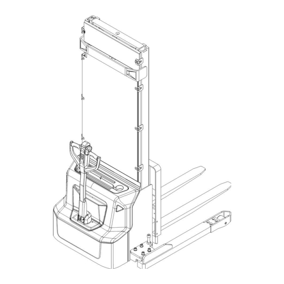
- Page 7 2. DESCRIPTION OF THE STACKER a. Overview of the main components Fig. 1: Overview main components Mast 10. Cover 20. Pin-code panel Load Backrest, Fork 11. Cover 21. LCD carriage 12. Main cover 22. Emergency button Fork 13. Cover 23. Spring cord Load roller assembly 14.
- Page 8 b. Main technical data Fig. 2: Technical data...
- Page 9 Table1: Main technical data for standard version Type sheet for industrial truck acc. to VDI 2198 PS E12BSL PS E12NSL Manufacturer`s type designation 3600 Battery Power (battery ,diesel, petrol, gas, manual) Pedestrian Operator type Q(t) Load Capacity / rated load c(mm) Load centre distance Load distance ,centre of drive axle to fork...
- Page 10 Lift motor rating at S3 7.5% Battery acc. to DIN 43531/35/36 A, B, C, V/Ah 2 x 12 / 85 24 / 60 Battery voltage, nominal capacity K5 2 x 27 Battery weight Kwh/h Energy consumption acc: to VDI cycle Type of drive control Sound level at driver’s ear acc.
- Page 11 d. Identification plate Designation, type Battery weight minimum/ maximum Serial number Nominal power in kW Rated capacity in kg Load center distance Supply voltage in V 10 Manufacturing date Own mass (self weight) in kg without battery 11 Option Name and address of manufacturer) If sold to the EU, here the place of the CE marking Fig.
- Page 12 3. WARNINGS, RESIDUAL RISK AND SAFETY INSTRUCTIONS DO NOT • Put foot or hand under or into the lifting mechanism. • Allow other person than the operator to stand in front of or behind the truck when it is moving or lifting/lowering. •...
- Page 13 4. COMMISSIONING, TRANSPORTING, DECOMMISSIONING a. Commissioning Table 2: Commissioning data Type PSE12BSL / 3600 PSE12NSL / 3600 Commissioning weight [kg] Dimensions 3600 3600 [mm] After receiving our new stacker or for re-commissioning you have to do following before (firstly) operating the truck: •...
- Page 14 Transportation DURING TRANSPORTATION ON A LORRY OR TRUCK ALWAYS FASTEN THE TRUCK SECURELY Lower the forks and park the truck securely. Fasten the truck according to Fig. 6 by fixing dedicated lashing belts to chassis, Fork carriage and mast, and fasten the other side at the transporting truck. c.
- Page 15 5. DAILY INSPECTION This chapter describes pre-shift checks before putting the truck into operation. Daily inspection is effective to find the malfunction or fault on this truck. Check the truck on the following points before operation. Remove load from truck and lower the forks. DO NOT USE THE TRUCK IF ANY MALFUNCTION IS FOUND.
- Page 16 6. OPERATION INSTRUCTIONS BEFORE OPERATING THIS TRUCK, PLEASE FOLLOW THE WARNINGS AND SAFETY INSTRUCTIONS (CHAPTER 3). Make sure, that the load is palletized and stable and that the daily inspection is carried out. PS E12BSL Pull out the emergency button (Fig.1, 22), type the password on pin-code panel and press √ button to start the truck.
- Page 17 The white markings on the mast indicate if the specific lifting limits reached. For instance with a load centre of gravity distance c of 600 mm and a maximum lift height H of 3600 mm, the max. Capacity Q is 1000 kg.
- Page 18 After starting the truck by activation from Pin-code panel carefully move the tiller to the operating zone (‘F’, fig.11). Turn the accelerator button to the desired direction forward ‘Fw.’ Or backwards ‘Bw.’(fig. 11). Control the travelling speed by moving the accelerator button (28) carefully until you reached the desired speed.
- Page 19 h. Malfunctions If there are any malfunctions or the truck is inoperative, please stop using the truck and activate the emergency button (22) by pushing it. If possible, park the truck on a safe area and press the X button of pin-code panel.
- Page 20 • There is leg injury risk when replacing the forks. • It’s forbidden to pull the fork to the direction of the operator. Operation steps: → Remove the safety bolt (33). → Release fork positioning device (34). → Move the forks to the center of fork holder and remove the forks through the groove. l.
- Page 21 7. PIN-CODE PANEL PS E12BSL is equipped optional with a pin-code panel. PS E12NSL is equipped standard with a pin-code panel and three ID cards. Introduction in-code panel is an electronic system which is similar with an electronic alarm system. Truck will not able to operate before typing a correct password, the main function is to prevent unauthorized operation.
- Page 22 8. BATTERY CHARGING AND REPLACEMENT • Only qualified personnel are allowed to service or charge the batteries. The instructions of this handbook must be observed. • PS E12BSL is lead acid battery, PS E12NSL is lithium battery • Recycling of batteries undergoes national regulations. Please follow these regulations.
- Page 23 b. Battery Indicator Battery discharged Battery charged Fig. 16: Battery discharge indicator Display An alpha-numeric liquid crystal display is fitted in the centre of the unit that shows the hours worked. The display is backlight (the backlight is normally lighted). Alarms The same display can also indicate the alarm state, showing a code corresponding to the type of alarm.
- Page 24 c. Charging • Before using the charger, please fully understand the instructions of the charger instructions. • Always follow these instructions. • The room, where you are charging must be ventilated. • The exactly charge status can be only checked from the discharge indicator. To control the status, the charging must be interrupted and the truck must be started.
- Page 25 9. REGULAR MAINTENANCE • Only qualified and trained personnel are allowed to do maintenance on this truck. • Before maintaining, remove the load and lower the forks to the lowest position. • If you need to lift the truck, follow chapter 4 b by using designated lashing or jacking equipment.
- Page 26 • 21 Check if correct fuses are used, if necessary replace. • 22 Test the audio warning signal • 23 Check the contactors • 24 Check the frame leakage (insulation test) • 25 Check function and wear of the accelerator •...
- Page 27 d. Checking electrical fuses Fig. 18: Location of fuses Table 5: Size of the fuses Rate 150A FU01 FU02 (PS E12NSL) 1.5A e. Removing, reattaching guarding DO NOT USE THIS TRUCK, IF THE GUARDING IS DAMAGED OR NOT CORRECTLY ASSEMBLED! If the guarding needs to be removed - de-attach holding clamps carefully.
- Page 28 TROUBLE SHOOTING • If the truck has malfunctions follow the instructions, mentioned in chapter 6. Table 6: Trouble shooting TROUBLE CAUSE REPAIR Lift only the max. capacity, Load weight too high mentioned on the ID-plate Battery discharged Charge the battery Check and eventually replace Lifting fuse faulty the lifting fuse...
- Page 29 Stop using and cool down the Electric system overheated truck Check and if necessary replace Defective heat sensor the heat sensor The controller is damaged. Replace the controller. The stacker starts up The accelerator not moves back to Repair or replace the suddenly its neutral position.
- Page 30 11. WIRING/ CIRCUIT DIAGRAM Electrical circuit diagram FU1 : 60 A FU2 : 150 A FU01 : 10 A Fig. 19: Electrical diagram manual steering PS E12BSL...
- Page 31 FU1 : 60 A FU2 : 150 A FU01 : 10 A FU02 : 1.5 A Fig. 20: Electrical diagram manual steering PS E12NSL...
- Page 32 Table 7: Description of electrical diagram Code Item Code Item Code Item Tiller Pump motor Limit switch Controller Driving motor Button switch Fuse Inter-lock switch Charger battery Lifting limit switch USB port Horn Sensor of speed reduction on curve Brake Contactor DC power switch Lowering valve...
- Page 33 SPECIALIZED STIPULATIONS FOR THE US- AMERICAN MARKET The content in this chapter is specialized for the US-American market. a. Foreword/ Compliance Operating this truck requires knowledge which can be acquired from this instruction handbook. This handbook must be kept available throughout the entire period of use of the industrial truck. IT IS LAW;...
- Page 34 b. Description warning labels (only US- market) Fig. 24: Warning labels and safety devices (only USA) A Crane hook label C Residual lift capacity sticker Sign danger being crushed E Identification plate (ID-plate) Sign warning stay clear stop truck F Sticker to read and follow these instructions Sign danger battery G Sign oil filling point M Sign warning electrical devices...
- Page 35 Sign read and follow this instruction (F) Sign warning stay clear stop truck (J) Sign oil filling point (G) Sign danger not riding (H) Sign danger battery (L) Sign warning electrical devices (M) Sign danger being crushed (I) Sign not under, on forks (N)
- Page 36 c. Technical data for US market...
- Page 37 Table 9: Main technical data for standard version (US market) Model PSE26BSL / PSE26NSL Mast Type Power Electric Operator Type Walkie Load Capacity 2600 Load Center Wheelbase 43.74 Weight Less Battery 1421 1466 1587 1609 1631 1675 Wheel Size Front (d x w) 8.27 x 2.76...
- Page 38 Turning Radius 52.95 Length w/ Outriggers 56.14 Travel Speed w/ wo Load 2.61 / 2.80 Lift Speed w/ wo Load 21.65 / 31.50 Lowering Speed w/ wo Load 25.59 / 21.65 Max Gradeability w/ wo Load 4 / 10 Service Brake electromagnetic 2x 12V Maintenance...
- Page 39 CE-DD-002 13. DECLARATION OF CONFORMITY (valid, if sold within the EU) [GB] CE Declaration of Conformity The signatory hereby declares that the specified machine conforms to the EU Directive 2006/42/EC (Machine Directive) and 2014/30/EU (Electro-Magnetic Compatibility, EMC) including their amendments as translated into national legislation of the member countries. The signatory is individually authorized to compile the technical documents.
- Page 40 nacionālajai likumdošanai. Parakstu īpašnieki ir atsevišķi pilnvaroti sastādīt tehniskās dokumentācijas. [N] EU-KONFORMITETSERKLÆRING Undertegnede bekrefter hermed at de enkelte betegnede maskin med kraftdrift tilsvarer de europeiske retningslinjene 2006/42/EC (maskinretningslinje) og 2014/30/EU (elektromagnetisk fordraglighet - EMV) inklusiv disses endringer og den tilsvarende rettsforordning til omsetning av nasjonal rett. Hver undertegnede er fullmektig til å...
Need help?
Do you have a question about the PSE26NSL and is the answer not in the manual?
Questions and answers