Table of Contents
Advertisement
Quick Links
INSTRUCTION HANDBOOK
Electric Pallet Truck
PTE12N
WARNING
Do not use the pallet truck before reading and
understanding these operating instructions.
NOTE:
• Please check the designation of your
present type at the last page of this
document as well as on the ID-plate.
• Keep for future reference.
Version 07/2019
PTE12N-SMS-001-EN
xyz
Advertisement
Table of Contents

Related Manuals for Noblelift PTE12N


Summary of Contents for Noblelift PTE12N
- Page 1 INSTRUCTION HANDBOOK Electric Pallet Truck PTE12N WARNING Do not use the pallet truck before reading and understanding these operating instructions. NOTE: • Please check the designation of your present type at the last page of this document as well as on the ID-plate.
- Page 3 FOREWORD Before operating the truck, read this ORIGINAL INSTRUCTION HANDBOOK carefully and understand the usage of the truck completely. Improper operation could create danger. This handbook describes the usage of different electric pallet trucks. When operating and servicing the truck, make sure, that it applies to your type. Keep this handbook for future reference.
-
Page 4: Table Of Contents
TABLE OF CONTENTS CORRECT APPLICATION ......................... 4 DESCRIPTION OF THE PALLET TRUCK ..................5 Overview of the main components ....................5 Main technical data ......................... 6 Description of the safety devices and warning labels (Europe and other, excepting USA) ... 8 Identification plate ........................... -
Page 6: Correct Application
1. CORRECT APPLICATION It is only allowed to use this electric pallet truck according to this instruction handbook. The trucks described in this handbook are self propelled electric power pallet trucks. The trucks are designed to lift, lower and transport palletized loads. A wrong usage can cause human injuries or can damage equipment. -
Page 7: Description Of The Pallet Truck
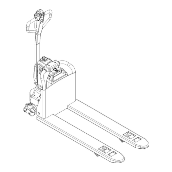
2. DESCRIPTION OF THE PALLET TRUCK a. Overview of the main components Fig. 1: Overview main components Safety (belly) button Fork Tiller Load roller Discharge indicator and charging indicating LED Battery Key switch Apron Emergency button Driving unit Hydraulic unit cover Side roller (option) Chassis... -
Page 8: Main Technical Data
b. Main technical data Fig. 2: Technical data Table 1: Main technical data for standard version Type sheet for industrial truck acc. to VDI 2198 PT E12N Manufacturer`s type designation Drive Battery Operator type Pedestrian Load Capacity / rated load Q (t) - Page 9 Load centre distance c (mm) Load distance ,centre of drive axle to fork x (mm) Wheelbase y (mm) 1185 Service weight Axle loading, laden front/rear 355 / 972 425 / 908 Axle loading, unladen front/rear 101 / 27 106 / 27 Polyurethane (PU) Tires ...
-
Page 10: Description Of The Safety Devices And Warning Labels (Europe And Other, Excepting Usa)
c. Description of the safety devices and warning labels (Europe and other, excepting USA) For the USA –market, the description of the safety and warning labels is mentioned in chapter 11. Fig. 3: Safety and warning labels Sticker to read and follow this instruction Capacity sticker Emergency button sticker Battery ID plate... -
Page 11: Identification Plate
d. Identification plate Designation, type Battery weight minimum/ maximum Serial number Nominal power in kW Rated capacity in kg Load center distance Supply voltage in V 10 Manufacturing date Own mass (self weight) in kg without battery 11 Option Name and address of manufacturer) If sold to the EU, here the place of the CE marking Fig. -
Page 12: Commissioning, Transporting, Decommissioning
• To prevent unintended sudden movements when not operating the truck (i.e. from another person, etc.), press emergency switch (5) or remove the key (4). 4. COMMISSIONING, TRANSPORTING, DECOMMISSIONING a. Commissioning Table 2: Commissioning data PTE12N PTE12N Type (540X1150) (685X1150) -
Page 13: Decommissioning
Park the truck securely and lash the truck according to the points identified in Fig. 5. Lift the truck to its destination and place the truck securely before removing the lifting gear. The lashing points are according to the Fig. 5. Transportation DURING TRANSPORTATION ON A LORRY OR TRUCK ALWAYS FASTEN THE TRUCK SECURELY... -
Page 14: Operating Instructions
• Check the smooth movement of the wheels. • Check the function of driving in both directions (section 6d). • Check the functions of braking by activation of tiller arm sensor, reversing of driving buttons, release of driving buttons and of the safety (belly) button (section 6f). •... -
Page 15: Lifting
Lifting DO NOT OVERLOAD THE TRUCK! THE MAXIMUM CAPACITY OF PTE12N IS 1200 kg. Travel with the lowered forks fully underneath the pallet and press the lifting button (Fig. 7, 16) until you reached the desired lifting height. c. Lowering Press the lowering button (17) carefully. -
Page 16: Steering
button (Fig.7,14) , press turtle button again to return back to regular mode. Press turtle button and hold for 2 seconds to activate driving function with tiller in its vertical position when operating in confined areas. The driving function is active only when turtle button is pressed (the speed is reduced);... -
Page 17: Battery Charging And Replacement
Table 3: Available batteries Model Battery PTE12N 24V15Ah lithium battery, 4.4kg IT IS ONLY ALLOWED TO USE LITHIUM BATTERIES. PLEASE CONSIDER THE MAXIMUM OPERATING TEMPERATURE OF THE BATTERIES. -
Page 18: Battery Indicator
b. Battery indicator Turtle Symbol: It is normally off, when it appears (fixed) it shows activation of the “soft” mode of the truck, in which maximum speed and acceleration are reduced. Battery State of charge Battery’s state-of-charge is indicated by four LED on the tiller: The 1st green LED from left is on, indicating 75% -100% of battery power. -
Page 19: Regular Maintenance
It’s also allowed to remove the battery out and charge in dedicated area. Fig.12: Battery charging Table 4: LED-Status LED- signal Function Charging Green Fully charged Table 5: Charger PTE12N Model Specification Input Output DZL2420SS02 24V5A (Chinese sticker) 180Vac -240Vac~2.0A MAX 29.4V 5.0A DZL2420SS02 24V5A (English sticker)... -
Page 20: Maintenance Checklist
Inspect the hydraulic oil level, refill if necessary • Refill the hydraulic oil ( 12 month or 1500 working hours ) • Check and adjust function of the pressure valve (1200kg(PTE12N)+0/+10%) Mechanical system • Inspect the forks for deformation and cracks •... - Page 21 • 34 Test the emergency braking • 35 Test the reverse and regenerative braking • 36 Test the safety (belly) button function • 37 Check the steering function • 38 Check the lifting and lowering function • 39 Check the tiller arm switch function General •...
-
Page 22: Lubricating Points
b. Lubricating points Lubricate the marked points according to the maintenance checklist. The required grease specification is: DIN 51825, standard grease. Fig. 13: Lubricating point s c. Check and refill hydraulic oil It is recommended to use hydraulic oil in connection with average temperature: –5℃~25℃... -
Page 23: Checking Electrical Fuses
Checking electrical fuses Remove the main cover. The fuses are located according to Fig. 14; the size is according to table 7. Fig. 14: Location of fuses for PTE12N Table 7: Size of the fuses Rate FU 1 FU 01... -
Page 24: Trouble Shooting
TROUBLE SHOOTING • If the truck has malfunctions follow the instructions, mentioned in chapter 6. Table 8: Trouble shooting TROUBLE CAUSE REPAIR Load weight too high Lift only the max. capacity, mentioned on the ID-plate Battery low power Charge the battery Lifting contactor failure Check and contact with service support for Load can’t be... -
Page 25: Wiring/ Circuit Diagram
10. WIRING/ CIRCUIT DIAGRAM a. Electrical circuit diagram PTE12N without speed reduction on curves Fig.15: Electric diagram FU 1 :10A FU 01 : 70A... - Page 26 Table 9: Description of electrical diagram Code Item Code Item Battery CAN tiller Controller Proximity switch Pump motor Traction motor Pump contactor Electromagnetic brake Emergency button 10A fuse Electromagnetic valve FU01 70A fuse Micro switch...
- Page 27 PTE12N with speed reduction on curves FU1 :10A FU01 : 70A Fig.16: Electric diagram...
- Page 28 Table 10: Description of electrical diagram Code Item Code Item Battery CAN tiller Controller Proximity switch Pump motor Traction motor Pump contactor Electromagnetic brake Emergency button 10A fuse Electromagnetic valve Proximity switch Micro switch FU01 70A fuse...
-
Page 29: Hydraulic Circuit
b. Hydraulic circuit Lifting cylinder Lowering valve Throttle valve Pressure control valve Hydraulic power unit Oil tank Fig. 17: Hydraulic circuit... -
Page 30: Specialized Stipulations For The Us- American Market
11. SPECIALIZED STIPULATIONS FOR THE US- AMERICAN MARKET The content in this chapter is specialized for the US-American market. a. Foreword/ Compliance Operating this truck requires knowledge which can be acquired from this instruction handbook. This handbook must be kept available throughout the entire period of use of the industrial truck. IT IS LAW;... -
Page 31: Description Warning Labels (Only Us- Market)
b. Description warning labels (only US- market) Fig. 18: Warning labels and safety devices (only USA) A Sticker to read and follow this instruction L Charger ID plate B Emergency button sticker M Name plate C Sign oil filling point N Capacity sticker D Warning sticker O Sign warning electrical device... - Page 32 Sign read and follow this instruction (D) Sign warning electrical devices (K) Sign no collision (N) Sign oil filling point (E) Sign warning stay clear stop truck (J) Sign emergency switch (P) Warning sticker...
-
Page 33: Technical Data For Us Market
c. Technical data for US market Fig. 19: Technical data US Table 11: Main technical data for standard version (US market) Type sheet for industrial truck acc. to VDI 2198 PT E26N Manufacturer`s type designation Drive Battery Operator type Pedestrian... - Page 34 Load Capacity / rated load Q (lbs) 2600 Load centre distance c (in) 23.6 Load distance ,centre of drive axle to fork x (in) 37.1 Wheelbase y (in) 46.7 Service weight Axle loading, laden front/rear 783/2143 937/2002 Axle loading, unladen front/rear 223/60 234/60 Polyurethane (PU)
-
Page 35: Declaration Of Conformity (Valid, If Sold Within The Eu)
CE-DD-002 12. DECLARATION OF CONFORMITY (valid, if sold within the EU) [GB] CE Declaration of Conformity The signatory hereby declares that the specified machine conforms to the EU Directive 2006/42/EC (Machine Directive) and 2014/30/EU (Electro-Magnetic Compatibility, EMC) including their amendments as translated into national legislation of the member countries. The signatory is individually authorized to compile the technical documents. - Page 36 nacionālajai likumdošanai. Parakstu īpašnieki ir atsevišķi pilnvaroti sastādīt tehniskās dokumentācijas. [N] EU-KONFORMITETSERKLÆ RING Undertegnede bekrefter hermed at de enkelte betegnede maskin med kraftdrift tilsvarer de europeiske retningslinjene 2006/42/EC (maskinretningslinje) og 2014/30/EU (elektromagnetisk fordraglighet - EMV) inklusiv disses endringer og den tilsvarende rettsforordning til omsetning av nasjonal rett. Hver undertegnede er fullmektig til å...
Need help?
Do you have a question about the PTE12N and is the answer not in the manual?
Questions and answers