Advertisement
Quick Links
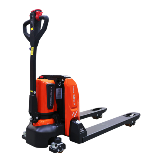
INSTRUCTION MANUAL
Electric Pallet Truck
PTE15N2 (PTE33N2) / PTE20N2 (PTE45N2)
WARNING
Do not use the pallet truck before reading and
understanding these operating instructions.
NOTE:
• Please check the designation of your
present type at the last page of this
document as well as on the ID-plate.
• Keep for future reference.
Version 10/2023
PTE15N2&PTE20N2-SMS-001-EN
Advertisement

Related Manuals for Noblelift PTE15N2


Summary of Contents for Noblelift PTE15N2
- Page 1 INSTRUCTION MANUAL Electric Pallet Truck PTE15N2 (PTE33N2) / PTE20N2 (PTE45N2) WARNING Do not use the pallet truck before reading and understanding these operating instructions. NOTE: • Please check the designation of your Version 10/2023 present type at the last page of this PTE15N2&PTE20N2-SMS-001-EN...
- Page 2 FOREWORD Before operating the truck, read this ORIGINAL INSTRUCTION MANUAL carefully and understand the usage of the truck completely. Improper operation could create danger. This manual describes the usage of different electric pallet trucks. When operating and servicing the truck, make sure, that it applies to your type.
- Page 3 TABLE OF CONTENTS CORRECT APPLICATION ......................... 2 DESCRIPTION OF THE TRUCK ....................... 3 Overview of the main components ....................3 Main technical data ......................... 4 Description of the safety devices and warning labels (Europe and other, excepting USA) ... 6 Identification plate (ID plate) ......................
- Page 4 1. CORRECT APPLICATION It is only allowed to use this electric pallet truck according to this instruction manual. The trucks described in this manual are self-propelled electric pallet trucks with electric control of lifting. The trucks are designed to lift, lower and transport palletized loads. Improper use can cause human injuries or can damage equipment.
- Page 5 ● Tiller bar ● Load roller ○ Safety socket ● Fork ● Gas spring ● Front panel ○ Side roller (PTE15N2) ● Lithium battery ● Side roller (PTE20N2) ● Cover ● Electromagnetic brake ● Emergency switch ● Drive wheel ○...
- Page 6 Main technical data Fig. 2: Technical data Table 2: Main technical data for standard version Technical data in line with VDI 2198 Model PTE15N2 PTE20N2 Drive Battery Battery Operation Pedestrian Pedestrian Load capacity/rated load Q (t) Load center distance...
- Page 7 Net weight with battery Axle loading,laden front/rear 500/1225 626/1002 621/1528 625/1528 Axle loading,unladen front/rear 96/29 99/29 115/34 119/34 Tyres ∅ x w ∅ 210×70 Tyre size,front ∅ 210×70 (mm) ∅ x w ∅ 74×93 /∅ 80×70 Tyre size,rear ∅ 80×70(∅ 80×93) (mm) (∅...
- Page 8 c. Description of the safety devices and warning labels (Europe and other, excepting USA) Fig. 3: Safety and warning labels Table . 3: Description of safety devices and warning labels Sticker (observe and follow the instructions) Decal (crane hook) Warning sticker (hands pinching) Identification plate Decal (emergency switch) Label (capacity)
- Page 9 d. Identification plate (ID plate) Designation, type Battery weight Min./Max in kg Serial number Nominal power in kW Rated capacity in kg Load center distance in mm Supply voltage in V Manufacturing date (MM/YY) Net weight in kg (without battery) Option Name and address of manufacturer) Check the ID plate taped on the truck for contents and type.
- Page 10 3. WARNINGS, RESIDUAL RISK AND SAFETY INSTRUCTIONS DO NOT Put foot or hand under or into the lifting mechanism. • • Allow other person than the operator to stand in front of or behind the truck when it is moving, lifting or lowering.
- Page 11 4. COMMISSIONING, TRANSPORTING, DECOMMISSIONING a. Commissioning Table 4: Commissioning data PTE15N2 PTE15N2 PTE20N2 PTE20N2 Type (PTE33N2) (PTE33N2) (PTE45N2) (PTE45N2) 540X1150 685X1150 540X1150 685X1150 Fork specification (21X45) (27X45) (21X45) (27X45) Commissioning weight 123 (271) 126 (278) 149 (328) 153 (337) [kg] (lbs)
- Page 12 Transporting ALWAYS FASTEN THE TRUCK SECURELY WHEN TRANSPORTED ON A LORRY OR A TRAILER. Lower the forks and park the truck securely. Fasten the truck according to Fig. 4 by attaching dedicated lashing straps to the truck and the transport vehicle and tension sufficiently.
- Page 13 5. DAILY INSPECTION This chapter describes pre-shift checks before putting the truck into operation. Daily inspection is effective to find the malfunction or fault on this truck. Check the truck on the following points before operation. Remove load from truck and lower the forks. DO NOT USE THE TRUCK IF ANY MALFUNCTION IS FOUND.
- Page 14 6. OPERATING INSTRUCTIONS BEFORE OPERATING THIS TRUCK, PLEASE FOLLOW THE WARNINGS AND SAFETY INSTRUCTIONS (CHAPTER 3). ENSURE THAT THE LOAD IS PLACED ON THE PALLET STABLELY AND CARRY OUT THE DAILY INSPECTION. Make sure that the load is palletized and stable, and that the daily inspection is carried out. Fig.5: Tiller controls Table.5: Tiller controls Item...
- Page 15 Lifting DO NOT OVERLOAD THE TRUCK! MAXIMUM CAPACITY OF PTE15N2 (PTE33N2) IS 1500KG (3307LBS). MAXIMUM CAPACITY OF PTE20N2 (PTE45N2) IS 2000KG (4409LBS). Before entering the pallet, fully lower the forks and move the truck to the appropriate position so that the center of gravity of the pallet (load) is approximately located in the center of the forks.
- Page 16 Press the turtle button (22) and hold it for 2 seconds to activate the driving function with tiller in vertical position when operating in confined areas. Steering Steer the truck by moving the tiller to the left or right side. Braking PLEASE CHECK THE BRAKING DISTANCE OF THE TRUCK BEFORE OPERATION.
- Page 17 Main codes and functions PTE15N2 (PTE33N2) is configured with a pin-code lock and supports 1 set of manual access code. The access code consists of four digits with numbers ranging from 0-9. PTE20N2 (PTE45N2) is configured with a pin-code lock and an ID card. It supports up to 5 ID cards and 1 set of access code.
- Page 18 8. BATTERY SAFETY, CHARGING AND REPLACEMENT Description of the lithium-ion battery The lithium-ion battery is a battery with rechargeable cells, the battery is designed for industrial trucks and can withstand related vibrations during operation. The battery is equipped with special connections for charging and discharging operations.
- Page 19 Battery identification plate Fig. 9: Battery identification plate Table 7: Description of battery identification plate Safety information Battery weight Rated voltage Operating temperature range Rated capacity CE mark and safety symbols Model designation Manufacturer Voltage range Manufacturer address The battery ID plate indicates the battery mass, and the center of gravity is approximately located in the center of the battery case.
- Page 20 Reversed connection of charging plug is prohibited. Follow the instruction for correct connection. For disconnection of charging plug use dedicated grip and never pull out the plug by means of cable. Stop charging immediately if any abnormalities are detected, e.g. severe temperature increase, deformation of battery case, smoke, noise etc.
- Page 21 Symbols - Safety and Warnings Table 8: Symbols - Safety and Warnings Used lithium-ion batteries must be treated as hazardous waste. Lithium-ion batteries marked with the recycling symbol and the sign showing a crossed- out waste bin must not be disposed of with ordinary household waste. Avoid fire and short circuits causing overheating.
- Page 22 • Powder extinguishers Metal fire extinguishers (PM 12i extinguishers) • • Metal fire powder PL-9/78 (DIN EN 3SP-44/95) Dry sand • Instructions for cooling an overheated, non-physically damaged battery This type of damage may be caused by a short circuit inside the battery, which may result in leakage of harmful materials, fire or battery explosion.
- Page 23 Instructions for safe handling of batteries Do not modify the battery. • • Do not open, damage, drop, penetrate or deform the battery. Do not throw the battery into a fire. • • Protect the battery from overheating. Protect the battery from direct sun light. •...
- Page 24 • The area for charging must be ventilated. The charge status of the battery is indicated by LEDs on the battery charger. • • The charging time depends on the battery charge status. The time it takes to charge an almost fully depleted battery depends both on the battery capacity and the charge current.
- Page 25 Table 9: LED-Status LED - Signal Function Charging Green Fully charged Display Discharged Fully charged Fig. 11: Tiller panel Replacement Park the truck securely, activate the emergency switch (16) by pressing it to turn off the truck. Hold the battery grip and unfix the latch (27), then vertically take out the battery. The installation is in the reverse order.
- Page 26 Inspect the hydraulic oil level, refill if necessary • Replace the hydraulic oil ( 12 month or 1500 working hours ) • • Check and adjust the pressure valve (1500kg (PTE15N2(PTE33N2)) +0/+10% or 2000kg (PTE20N2(PTE45N2))+0/+10%)) Mechanical system Inspect the forks for deformation and cracks •...
- Page 27 Inspect the electric wiring for damage • Check the electric connections and terminals • Test the Emergency switch function • Check the electric drive motor for noise and damages • Test the display • Check, if correct fuses are used •...
- Page 28 Lubricating points Lubricate the marked points according to the maintenance checklist. The required grease specification is: DIN 51825, standard grease. Fig. 13: Lubricating point s Check and refill hydraulic oil It is recommended to use hydraulic oil in accordance with average temperature: Table 11: Hydraulic oil tyoe Environment –5℃~25℃...
- Page 29 Check the electrical fuses Fig. 14 Location of fuses Table 8: Fuse PTE15N2 (PTE33N2) PTE20N2 (PTE45N2) FU01 FU02...
- Page 30 TROUBLE SHOOTING • IF TRUCK HAS MALFUNCTIONS, FOLLOW THE INSTRUCTIONS IN CHAPTER 6. Table 13: Trouble shooting TROUBLE CAUSE REPAIR Lift only the max. capacity, mentioned on Load weight too high the ID-plate Battery low power Charge the battery Load can’t be lifted Check and contact with service support for Lifting contactor failure...
- Page 31 WIRING/ CIRCUIT DIAGRAM Electrical diagram PTE15N2 (PTE33N2) without speed reduction in steering Fig. 15: Electrical diagram Table 14: Description of electrical diagram Code Item Code Item Battery CAN tiller Controller Proximity switch Pump motor Traction motor Pump contactor Electromagnetic brake...
- Page 32 PTE15N2 (PTE33N2) with speed reduction in steering Fig. 16: Electrical diagram Table 15: Description of electrical diagram Code Item Code Item Battery CAN tiller Controller Proximity switch Pump motor Traction motor Pump contactor Electromagnetic brake Emergency switch Proximity switch Electromagnetic valve...
- Page 33 PTE15N2 (PTE33N2) with integrated charger, without speed reduction in steering Fig. 17: Electrical diagram Table 16: Description of electrical diagram Code Item Code Item Battery CAN tiller Controller Proximity switch Pump motor Traction motor Pump contactor Electromagnetic brake Emergency switch...
- Page 34 PTE15N2 (PTE33N2) with integrated charger and speed reduction in steering Fig. 18: Electrical diagram Table 17: Description of electrical diagram Code Item Code Item Battery CAN tiller Controller Proximity switch Pump motor Traction motor Pump contactor Electromagnetic brake Emergency switch...
- Page 35 PTE20N2 (PTE45N2) with speed reduction in steering Fig. 19: Electrical diagram Table 18: Description of electrical diagram Code Item Code Item Battery CAN tiller Controller Proximity switch Pump motor Traction motor Pump contactor Electromagnetic brake Emergency switch 10A fuse Electromagnetic valve FU01 70A fuse Micro switch...
- Page 36 PTE20N2 (PTE45N2) with integrated charger and speed reduction in steering Fig. 20: Electrical diagram Table 19: Description of electrical diagram Code Item Code Item Battery CAN tiller Controller Proximity switch Pump motor Traction motor Pump contactor Electromagnetic brake Emergency switch 10A fuse Electromagnetic valve FU01...
- Page 37 Hydraulic diagram Lifting cylinder Lowering valve Throttle valve Pressure control valve Hydraulic power unit (pump and motor) Oil tank Fig. 21: Hydraulic circuit...
- Page 38 SPECIALIZED STIPULATIONS FOR THE US- AMERICAN MARKET The content in this chapter is specialized for the US-American market. Foreword/ Compliance Operating this truck requires knowledge which can be acquired from this instruction handbook. This handbook must be kept available throughout the entire period of use of the industrial truck. IT IS LAW;...
- Page 39 Identification plate Truck Model Option Serial Number Maximum Battery Capacity (Ah) Supply Voltage (Volts) Battery Weight Min/Max lbs. (kg) Truck Weight with Max. Battery, lbs (Kg) Battery Manufacturer Information Truck Weight without Battery, lbs. (Kg) Battery Model Number Manufacturing Date (MM/YYYY) Battery Amp Hour Rate Load Center Distance (mm) Maximum Capacity (Uniformly Distributed load)
- Page 40 Description of warning labels (only US- market) Fig. 23: Warning labels and safety devices (only US market) Table 20: Description of warning labels and safety devices Sticker (observe and follow the instructions) Decal (crane hook) Warning sticker (hands pinching) Identification plate (ID-plate) Decal (emergency switch) Label (capacity) Sign oil filling point...
- Page 41 Technical data for US market Fig. 24: Technical data (US market) Table 21: Main technical data for standard version (US market) Technical data in line with VDI 2198 Model PTE33N2 PTE45N2 Drive Battery Battery Operation Pedestrian Pedestrian Q (lbs) 4409 Load capacity/rated load 3307 Load center distance...
- Page 42 Load distance x (in) 37.4 37.3 Wheelbase y (in) 46.7 46.8 Net weight with battery Axle loading,laden front/rear 1102/2701 1380/2209 1369/3369 1378/3369 Axle loading,unladen front/rear 212/64 218/64 115/34 119/34 Tyres Tyre size,front ∅ x w (in) ∅ 8.3×2.8 ∅ 8.3×2.8 ∅...
- Page 43 CE-DD-003 DECLARATION OF CONFORMITY (valid, if sold within EU) [GB] Original CE Declaration of conformity The signatory hereby declares that the specified machine conforms to the EC Directive 2006/42/EC (Machine Directive), and 2014/30/EU (Electro-Magnetic Compatibility, EMC) including their amendments as translated into national legislation of the member countries. The signatory is individually authorized to compile the technical documents and declares that the following standards, including the normative procedures contained therein, have been applied: [D] Original EG- Konformitätserklärung Der Unterzeichner erklärt hiermit, dass die angegebene Maschine den EG-Richtlinien 2006/42/EG (Maschinenrichtlinie) und 2014/30/EU (Elektromagnetische...
- Page 44 (1) Type: XXXXXXXX (2) Serial No: YYYY (3) Year of constr.: (4) Manufacturer: Noblelift Intelligent Equipment Co., Ltd. 528 Changzhou Road, Taihu Sub-district, Changxing, 313100, PR China (5) Res : <Company name>, ponsible for compiling the technical documentation <Company Address>...
Need help?
Do you have a question about the PTE15N2 and is the answer not in the manual?
Questions and answers