
Related Manuals for Dantherm HCC360 E1-A-BP-RH


Summary of Contents for Dantherm HCC360 E1-A-BP-RH
- Page 1 Original operating and service instructions HCC 260 P1 - HCC 360 P2 - HCC 360 E1 | en | *108478* 108478 Rev. 1.1 · 2023-W36...
-
Page 3: Table Of Contents
Table of contents Table of contents Introduction ................4 Overview . -
Page 4: Introduction
Copyright No part of this manual may be reproduced without the prior written permission of Dantherm. Reservations Dantherm reserves the right to make changes and improvements to the product and the manual at any time without any obligation to give prior notice. - Page 5 Introduction: Overview The following abbreviations are used in this manual: Abbreviations in this manual Abbreviation Description Outside air inlet into the unit Supply air from the unit into the dwelling Extract air from the dwelling into the unit Exhaust air from the unit to the outside Temperature sensor no 1 Temperature sensor no 2 Temperature sensor no 3...
-
Page 6: Symbols Used In The Operating Instructions
Introduction: Symbols used in the operating instructions Symbols used in the operating instructions In these operating instructions, particularly important text passages are highlighted with signal words and symbols that are described below. Signal words DANGER ...indicates a hazard which, if not avoided, will result in death or serious injury. WARNING ...indicates a hazard which, if not avoided, could result in death or serious injury. -
Page 7: Product Description
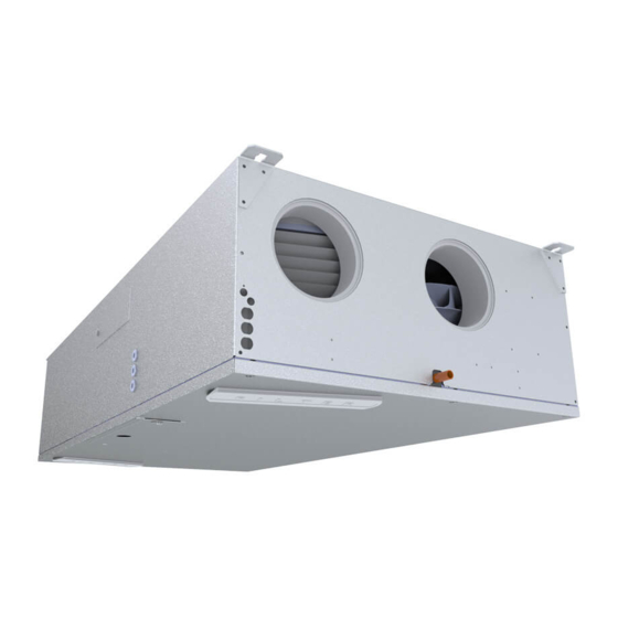
Product description: General description Product description General description The residential ventilation unit HCC 260/360 is designed to provide dwellings with fresh air Introduction via a heat exchange from the extract air to the supply air. This results in a low energy loss. The unit is designed for wall mounting or installation underneath a ceiling in dry surroundings, with temperatures > 12 °C., e.g. - Page 8 Product description: General description Nameplate The nameplate is located on the cover of the control board next to the control panel. Fig. 2: Nameplate This figure indicates the air flow paths through the unit. Further information on changing the Airflows operating mode can be found on page 19. Fig. 3: Air flow paths inside the unit...
- Page 9 Product description: General description This figure indicates the correct placement of the sensors (if available) inside the unit. Positioning of the sensors Fig. 4: Positioning of the sensors Item Operating mode A (default) Item Operating mode B Outside air sensor T1 Extract air sensor T3 Supply air sensor T2 Exhaust air sensor T4 Extract air sensor T3 Outside air sensor T1...
-
Page 10: Components Description
Product description: Components description Components description The individual components of the units included in the standard scope of delivery are described in this section. Cabinet The outer parts of the cabinet are made of aluzinc sheet metal. To add accessories or replace components, the front cover must be removed. -
Page 11: Accessories
The preheater is an external cabinet that is connected to and controlled by the control unit of the HCC 260/360. To control the HCC 260/360, Dantherm recommends using a remote control specifically Hand-held remote designed for this unit series. - Page 12 Product description: Accessories VOC and humidity The HCC 260/360 can be fitted with VOC sensors (volatile organic compounds) and/or humidity sensors (RH %) (see page 10). These sensors provide a continuous quality control of sensors the indoor air and adjust the airflow accordingly, which results in sufficient ventilation with the lowest possible electrical power consumption.
-
Page 13: Special Operating Modes
Product description: Special operating modes Special operating modes In this section, the operation of the system under special conditions is described. For details on the standard operating modes, please refer to page 32. Preheating (with If a preheating coil is installed, the unit can additionally heat the outdoor air (T1) electrically to reduce the risk of frost and increase the supply air temperature. - Page 14 Product description: Special operating modes Alternative If there is a fireplace in the house, the alternative defrosting procedure is selected via the PC tool and will trigger the following steps: defrosting procedure • The speed of the supply air fan and exhaust air fan decreases slowly until the minimum speed is reached.
-
Page 15: Installation
Installation: General requirements Installation General requirements The following should be considered when selecting an appropriate installation site: Installation site and directing the air 1. The unit is intended for installation in dry environments at temperature levels >12 °C, duct connections e.g. in utility rooms or rooms with similar heating requirements. 2. - Page 16 Installation: General requirements Space If the unit is to be installed under the ceiling, please take into account the space that is required to tilt the unit upwards and downwards. Also provide for sufficient additional space requirements for if an electric preheater is to be installed. ceiling mounting Additional space (1) is needed next to the unit to be able to lift the unit onto the bracket.
- Page 17 Installation: General requirements If the unit is to be mounted on the wall, T1 and T4 (cold ducts) must always be located at the Space requirement bottom of the unit. If the unit is equipped with an additional preheater, please also provide for wall mounting for sufficient space (1) for the preheater: 1122...
-
Page 18: Installation Options
Installation: Installation options Installation options The unit offers a variety of installation options, such as vertical or horizontal mounting, flexible cable routing and flexible air duct connections, making the unit suitable for a wide range of installation sites. Check the installation options and decide which is most suitable for the demands on site. - Page 19 Installation: Installation options The air ducts leading into the dwelling can either be connected to the right or left side. Selection of the Operating mode A is set as standard. (Carry out the steps in the Switch to operating mode B operating mode section to switch to operating mode B).
- Page 20 Installation: Installation options Changing to If local systems require operating mode B, follow the procedure below and check the information on the label to connect the water drain properly. operating mode B 1. Open the small cover located close to the filter flaps on the long side of the unit. Fig. 16: Opening the cover 2.
- Page 21 Installation: Installation options 5. Change the filter (ONLY if the optional pollen filter ePM1 is used for the supply air). For information on the correct positioning of the ePM1 filter for operating mode A/B, please refer to the table on page . Fig. 20: Positioning of the filters 6.
-
Page 22: Assembly
Installation: Assembly Assembly The enclosed bracket can and should be used for both wall and ceiling installation. Using the Multi-purpose bracket will automatically tilt the unit by 1 into the direction of the condensate drain when mounting bracket the unit is mounted under the ceiling or on the wall. Fig. 21: Mounting the bracket for ceiling mounting (left) and wall mounting (right) Wall mounting Please proceed as follows to mount the unit vertically on a wall:... - Page 23 Installation: Assembly Please proceed as follows to mount the unit on the ceiling: Ceiling mounting 1. The unit should always be tilted at least 1° towards the drain side (T4). To do so, use the supplied bracket that is to be attached to the T4 end of the unit. Drill two holes and attach the bracket according to the ceiling configuration (see section Multi-purpose mounting bracket).
- Page 24 Installation: Assembly Connecting the Connect the air ducts (specifications in accordance with local regulations). Use connections with spigots only. duct system Warning: NEVER screw duct spigots directly into the sheet metal of the unit. Fig. 25: Correct connection of the air ducts Insulate the air ducts in accordance with local requirements, taking into account the ambient temperature of the installation.
- Page 25 Installation: Assembly It is essential to connect a condensation drain hose to the unit, as the air humidity from the Condensate drain – extract air condenses inside the heat exchanger. General The condensate is harmful to the environment if it is not handled properly. Therefore, a suitable condensate drain hose must be connected that is both flexible and able to withstand constant bending.
-
Page 26: Connecting Additional Equipment
Installation: Connecting additional equipment Connecting additional equipment DANGER Risk of electric shock! You can be severely injured by an electric shock. • Always disconnect the unit from the mains by removing the mains plug from the socket before opening the unit! •... - Page 27 Modbus RTU via the RS485 port nor via the Dantherm accessories (HAC, FPC or HCP11). Modbus TCP/IP The control units of the Dantherm ventilation units are suited to use the Modbus communication protocol TCP /IP via the Ethernet port. This is used for Building Management Systems (BMS) or for communicating with smartphone apps.
- Page 28 Installation: Connecting additional equipment Digital input The unit is equipped with 2 override inputs, also named digital inputs. These inputs can be used to select a different fan speed or to activate alarms. By default, the digital inputs are set as follows: •...
-
Page 29: Initial Start-Up And Calibration
Installation: Initial start-up and calibration Initial start-up and calibration The unit must be calibrated after the installation to adapt it to any specific air duct system. To do so, connect a computer with MS Windows operating system to the USB port, which is hidden under a black rubber cover on the front panel, and start the PC tool software specific to this type of unit. - Page 30 Installation: Initial start-up and calibration 3. Connect the measuring device for determining the ΔPa value via the extract air duct (as depicted). The example given is based on a unit configuration in operating mode A. Fig. 34: Pressure measurement P3–P4 4. Adjust the speed of the extract air fan according to the instructions given in the PC tool on your computer.
- Page 31 Installation: Initial start-up and calibration 6. Adjust the speed of the supply air fan according to the instructions given in the PC tool on your computer. The aim is to adjust the fan until the ΔPa measuring device shows the value of the pressure drop that has been read from the display in step 2. 7.
-
Page 32: Operation
Dantherm PC tool, the Dantherm ResidentialApp or an additional remote control (HCP 10/11 or HRC3). Note, however, that mandatory minimum values for air exchange may apply. -
Page 33: Temporary Operating Modes (Override)
Operation: Temporary operating modes (override) When operation according to the weekly program is activated, the unit will automatically Operation adjust the fan speed to a preset week program. according to week program The unit comes with 11 week programs (10 preset + one customisable program in the PC tool). -
Page 34: User Rights
Operation: User rights User rights This unit is designed for hidden installation. For this reason, user intervention can only be performed via external devices, i.e. either by a wireless remote control or a smartphone app. Please refer to the respective manual for these accessories for the relevant instructions. Users can obtain the PC tool from their local retailer and carry out the specified functions. - Page 35 Operation: User rights Function Wired remote Hand- Smart- PC tool control held phone remote control Time and Date Indication and setting of time/date Selection of week program no. Individual settings for week program 11 Indication of the operating time counter Indication of date of installation Manual calibration of nominal speed PC tool instructions Network...
-
Page 36: Maintenance And Troubleshooting
Find out more on page 34. However, filters must be checked at least once every six months. Dantherm always recommends replacing the filter at least once a year. When checking the filters, also clean the outside of the unit around the filter openings with a damp cloth. -
Page 37: Cleaning The Interior Of The Unit
Maintenance and troubleshooting: Cleaning the interior of the unit The drain and water hose must be checked annually. Drain and Check whether the condensation drain hose is properly attached to the unit and that the condensation drain siphon is filled with water. Check the water hose for kinks and for a minimum inclination of hose (annually) 1 % from the unit towards the drain. - Page 38 Maintenance and troubleshooting: Cleaning the interior of the unit Cleaning the 1. Remove the drain hose and turn all the depicted locks by 90°. condensation tray and condensate drain Fig. 38: Opening the locks 2. Remove the condensation tray. Note that the condensation tray may contain small amounts of water when mounted on the ceiling.
- Page 39 Maintenance and troubleshooting: Cleaning the interior of the unit Cleaning the fan NOTICE When cleaning the fan blades, make sure that the metallic balancing weights attached to the fan blades are not removed or displaced. 1. Clean the fan blades with compressed air or a brush. Each blade must be cleaned in a way that the fan remains balanced.
-
Page 40: Troubleshooting
Maintenance and troubleshooting: Troubleshooting Troubleshooting In this section you will get to know how to detect and correct possible operating errors. Dantherm strongly recommends to connect a remote control to the unit for operation in order to perform proper troubleshooting. Error signals... - Page 41 Maintenance and troubleshooting: Troubleshooting After any inspection or repair carried out due to potential errors, the unit can be reset by Resetting errors disconnecting the unit from the 230 V AC supply and then reconnecting it. This way, the control unit is reset. The unit will resume normal operation and also starts a new search for potential errors.
- Page 42 Maintenance and troubleshooting: Troubleshooting A B C Error Fault Potential cause Action required Reset code 3 R 0 E3 Bypass damper does Switch position A: Check whether bypass is Automatic reset not close as bypass is closed, but activated in PC tool when efficiency is expected supply air temperature high enough for...
- Page 43 Maintenance and troubleshooting: Troubleshooting A B C Error Fault Potential cause Action required Reset code 5 R 1 E5 Supply air Temperature sensors Mount temperature Automatic reset if temperature are not mounted sensor(s) correctly the temperature is sensor (T2) correctly within the normal range for 30 seconds Resistance in one of the Replace temperature...
- Page 44 Maintenance and troubleshooting: Troubleshooting A B C Error Fault Potential cause Action required Reset code 11 R 0 E11 Supply air Low temperatures from Ensure that all ventilated Manual reset by temperature < +5 °C unheated rooms rooms are heated pressing the alarm button or by Reduced heat Alternatively, close the air switching the unit...
- Page 45 Maintenance and troubleshooting: Troubleshooting A B C Error Fault Potential cause Action required Reset code 14 R 2 E14 Fire alarm Fire or smoke sensor Check for smoke or fire The alarm indicator Fire protection connected to this input can be reset by Check if sensor and thermostat is active...
-
Page 46: Annex
Annex: Technical data Annex Technical data TECHNICAL DATA Abbr. Unit HCC 360 HCC 260 HCC 360 Max. nominal flow rate Operating range DIBt (German VDIBt 70 to 140 Institute for Building Technology) Operating range passive house VPHI 70 to 140 @ 100 Pa EN 13141-7 reference flow rate Vref @ 50 Pa... - Page 47 Annex: Technical data TECHNICAL DATA Abbr. Unit HCC 360 HCC 260 HCC 360 Fire protection class of the polystyrene insulation according to DIN 4102-1 Fire protection class of the polystyrene insulation according to EN 13501-1 ELECTRICAL SPECIFICATIONS Electrical voltage Max. power consumption 161/ 1061 127/ 1027 161/ 1061 (without/with preheater) Frequency...
-
Page 48: Cabinet Dimensions
Annex: Cabinet dimensions Cabinet dimensions Fig. 42: Dimension drawing of the cabinet... -
Page 49: Main Pcb With Connections
Annex: Main PCB with connections Main PCB with connections 1: Power 2: Gnd 1: 12vDC / 750mA out 3: Shield 2: Input 1 4: RS485_A 3: Input 2 5: RS485_B 4: GND 6: Gnd Digital input RS485 FACTORY ONLY J2 J4 J6 J7 230V Pre- FAN1 FAN2... -
Page 50: Week Programs Of The Time Switch
Annex: Week programs of the time switch Week programs of the time switch The following illustrations indicate the preset fan stages for one day (0 to 24 h) in the respective programs. Each of the programs offers two settings: • Weekdays (Mon–Fri) •... - Page 51 Annex: Week programs of the time switch Program 6 2 2 2 2 2 2 2 2 2 2 2 2 2 2 Weekdays 1 1 1 1 1 1 1 1 2 2 2 2 2 2 2 2 2 2 2 Weekend 1 1 1 1 1 1 1 1 1 1 1 1 1...
-
Page 52: Spare Parts
Annex: Spare parts Spare parts If spare parts are required, please visit Dantherm's online shop: shop.dantherm.com... -
Page 53: Declaration Of Conformity (Eu)
Annex: Declaration of conformity (EU) Declaration of conformity (EU) Dantherm hereby declares that the unit mentioned below: No.: 352444 Type: HCC 260/360 – complies with the following directives: 2014/35/EU Low Voltage Directive 2014/30/EU EMC Directive 2014/53/EU Radio Equipment Directive 2009/125/EC Eco Design Directive (incl. Regulation 2014/1253) -
Page 54: Declaration Of Conformity (Ukca)
Annex: Declaration of conformity (UKCA) Declaration of conformity (UKCA) Dantherm, Marienlystvej 65, DK-7800 Skive, declares that the unit mentioned below: Type: HCC 260/360 Item no.: 352444 – confirm with the following directives: UK SI 2016 No. 1101 Electrical Equipment (Safety) Regulations 2016 UK SI 2016 No. - Page 56 Marienlystvej 65 7800 Skive Denmark www.danthermgroup.com Dantherm can accept no responsibility for possible errors and changes (en) Der tages forbehold for trykfejl og ændringer (da) Irrtümer und Änderungen vorbehalten (de) Dantherm n’assume aucune responsabilité pour erreurs et modifications éventuelles (fr)
Need help?
Do you have a question about the HCC360 E1-A-BP-RH and is the answer not in the manual?
Questions and answers