Table of Contents
Advertisement
Copyright © Tyan Computer Corporation, 2003-2004. All rights reserved. No part of this manual
may be reproduced or translated without prior written consent from Tyan Computer Corp.
All registered and unregistered trademarks and company names contained in this manual are
property of their respective owners including, but not limited to the following.
Tyan, Thunder LE-T S2518 are trademarks of Tyan Computer Corporation.
Intel, Intel Pentium, combinations thereof are trademarks of Intel Corporation.
ServerWorks, ServerSet III LE3, combinations thereof are trademarks of Broadcom/ServerWorks,
Corp.
AMI, AMI BIOS are trademarks of American Megatrends Inc.
Microsoft, Windows are trademarks of Microsoft Corporation.
IBM, PC, AT, PS/2 are trademarks of IBM Corporation.
Winbond is a trademark of Winbond Electronics Corporation.
Micronics is a trademark of Micronics Corporation.
Portable Document Format (PDF) is a trademark of Adobe Corporation.
Iomega, Zip are registered trademarks of Iomega Corporation.
Information contained in this document is furnished by Tyan Computer Corporation and has been
reviewed for accuracy and reliability prior to printing. Tyan assumes no liability whatsoever, and
disclaims any express or implied warranty, relating to sale and/or use of Tyan products including
liability or warranties relating to fitness for a particular purpose or merchantability. Tyan retains the
right to make changes to product descriptions and/or spec ifications at any time, without notice. In
no event will Tyan be held liable for any direct or indirect, incidental or consequential damage, loss
of use, loss of data or other malady resulting from errors or inaccuracies of information contained in
this document.
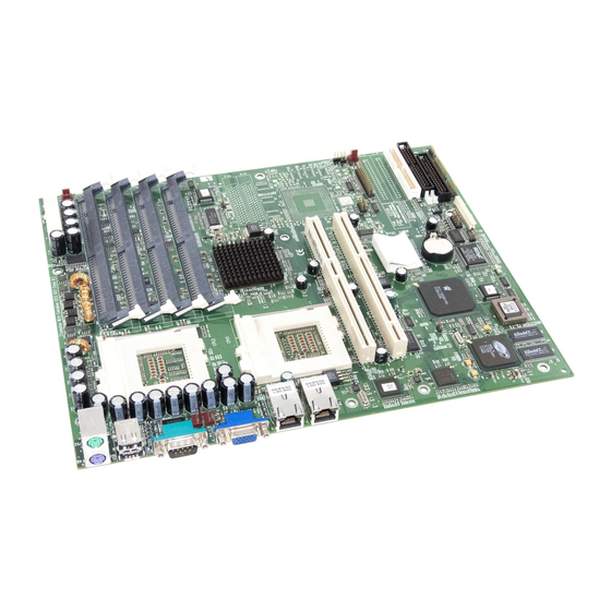
Thunder LE-T
S2518
User's Manual
Revision 1.20
1
http://www.tyan.com
Advertisement
Table of Contents

Related Manuals for TYAN THUNDER LE-T


Summary of Contents for TYAN THUNDER LE-T
- Page 1 In no event will Tyan be held liable for any direct or indirect, incidental or consequential damage, loss of use, loss of data or other malady resulting from errors or inaccuracies of information contained in this document.
-
Page 2: Table Of Contents
3.2e Onboard Device Configuration ……………………………………………Page 37 3.2f Even Log Configuration ……………………………………………Page 38 3.2g Remote Access Configuration ……………………………………………Page 38 3.3 Chipset ……………………………………………Page 38 3.4 PCIPnP ……………………………………………Page 39 3.5 Boot ……………………………………………Page 40 3.6 Power ……………………………………………Page 40 3.7 Security ……………………………………………Page 40 3.8 Exit ……………………………………………Page 40 http://www.tyan.com... - Page 3 ……………………………………………Page 41 SCSI Setup Section ……………………………………………Page 45 Chapter 5: System Resources ……………………………………………Page 55 5.1 Beep Codes ……………………………………………Page 55 5.2 Flash Utility ……………………………………………Page 55 Appendix I: Hardware Monitoring Information ……………………………………………Page 56 Appendix II: Glossary ……………………………………………Page 57 Technical Support ……………………………………………Page 62 http://www.tyan.com...
-
Page 4: Before You Begin
1x Ultra160 SCSI cable (for optional SCSI if included onboard) 1x 64-bit PCI Riser card 1x Cable set: 9-pin Serial and 25-pin printer cables 1x Thunder LE-T user’s manual 1x Tyan driver CD 1x Adaptec 7899W NT Ultra160 SCSI driver diskette (if optional SCSI included) -
Page 5: Chapter 1: Introduction
Pentium III processing. Designed to be portable as well as flexible, the Thunder LE-T can fit into standard ATX chassis and 1U and 2U rackmount chassis. This platform utilizes ServerWorks’ high-performance ServerSet III LE3 chipset, enabling next generation application and platform support. -
Page 6: Software Specifications
Windows NT/2000/XP, Red Hat Linux 7.x* *Support of Red Hat 7.x is limited by Red Hat’s customer support for this product and version Tyan takes no responsibility and will not be held liable if Red Hat should no longer support Red Hat 7.x. -
Page 7: Chapter 2: Board Installation
Chapter 2: Board Installation Installation You are now ready to install your motherboard. The mounting hole pattern of the Thunder LE-T matches the ATX system board specifications. Your chassis should support a standard ATX motherboard form factor. How to install our products right… the first time The first thing you should do is read this user’s manual. -
Page 8: Front Panel Connector
2.1 Front Panel Connector (J80) Your chassis will usually come with connectors to install onto the motherboard, such as HDD and Power LEDs. The Front Panel Connector (J80) has been implemented for such purposes. Infrared (IrDA) http://www.tyan.com... -
Page 9: Cmos Reset
Open J58, then power on the system again By following this procedure, you will erase your password and reset the CMOS. The location of J58 is shown in the diagram below. OPEN Normal * default is OPEN OPEN Normal http://www.tyan.com... -
Page 10: Pci Speed Jumper
* default is OPEN CLOSE 33MHz * Onboard Adaptec 7899W, if available on your Thunder LE-T, runs on a 66MHz SCSI bus. After setting the SCSI bus to 33MHz, the Adaptec 788W will be downgraded to 64-bit / 33MHz speed. -
Page 11: Fsb Speed Jumper
CPU can handle will damage the CPU. NOTE Tyan takes no responsibility and will not be held liable for damage related to the operation of the CPU(s) using different settings from those of the CPU manufacturer’s specified default settings. - Page 12 2.5 LAN1 and LAN2 Activity LEDs Headers (J62) With these headers, the activity of the two LAN ports can be viewed from external LEDs. NIC1 NIC2 NIC2 NIC1 ACT. ACT. Yellow = Activity Green = Link + 10 Base Orange = Link + 100 Base http://www.tyan.com...
-
Page 13: Fan Connectors (Fan 1 To 6)
The FAN connectors, with the exception of FAN5 and FAN6 are 12V at NOTE 1.2A and only support cooling fans below or up to that rating. Tyan takes no responsibility and will not be held liable for damage related to the misuse of these fan headers. -
Page 14: Speaker Connector
2.7 Speaker Connector (J19) This header can be used to connect a 4-pin speaker. SPEAKER PWR IN http://www.tyan.com... -
Page 15: Cpu Voltage Id Mismatch Led
Solution: turn off machine, put single CPU into CPU1 instead of CPU2 Attempt to operate with two CPUs of differing voltages Solution: turn off machine, install CPUs of same voltage The locations of CPU1, CPU2, and D38 are shown in the diagram below . CPU2 CPU1 http://www.tyan.com... - Page 16 These (optional) headers can be used to define Promise IDE devices to the onboard ATA - 100/IDE RAID channels. J70 is the Primary ATA-100/IDE RAID connector, J71 is the Secondary ATA-100/IDE RAID connector, and J83 controls the Promise chips. J83 works with Rev.1.07 BIOS: Closed Enables RAID Promise chip Enables ATA-100 Promise chip Open http://www.tyan.com...
-
Page 17: Scsi Connectors
RAID ports. During the time when the system boots, the Nighthawk SCSI NOTE RAID BIOS will be shown on the screen. Also, make sure to enabled the 7899W controller in the BIOS to activate it onboard (if 7899W controller included). http://www.tyan.com... -
Page 18: Parallel Port Connector
2.11 Parallel Port Connector (J77) This header can be used to connect a parallel port cable. http://www.tyan.com... -
Page 19: Usb Port Headers
2.12 USB Port Headers (J72, J73) These headers can be used to connect additional USB ports. If you intend to install front-side USB ports, please check if your chassis is compatible for such a configuration. Tyan does not provide front-side USB NOTE cables. -
Page 20: Serial Port Header
2.13 Serial Port Header (J81) This header can be used to connect an additional serial port. http://www.tyan.com... -
Page 21: Slim Floppy Connector (Optional)
2.14 Slim Floppy Connector (optional) There may be an (optional) slim floppy connector on your Thunder LE-T. The location is shown below. SLIM FDD http://www.tyan.com... -
Page 22: Riser Card Information
2.15 Riser Card Information Compatible Riser Card Model Numbers M2037 M2038 http://www.tyan.com... -
Page 23: Hardware Reset Switch Connector
2.17 BIOS Flash Utility You can upgrade the BIOS of this motherboard by using the Flash Utility. See the System Resources page 45 for details. Also check that you have the newest BIOS, available from the Tyan website: http://www.tyan.com http://www.tyan.com... -
Page 24: Mounting The Motherboard
The diagrams above are only representative of a few solutions for installing a NOTE motherboard into the chassis. The installation procedure for installing your motherboard into the chassis may differ. http://www.tyan.com... -
Page 25: Installing Memory
Please keep in mind that although some memory modules may appear to be high-quality, they may contain inferior or substandard parts. The type of memory you choose to install should be checked against the memory compatibility list, which is available from Tyan’s website at http://www.tyan.com. -
Page 26: Installing Cpu And Cooling Fans
2.20 Installing the CPU and Cooling Fans Intel Pentium III (PGA370) processors can be used on this board. For more information on CPU compatibility, check Tyan’s website at http://www.tyan.com/ When installing your CPU, remember the following: The CPU is a sensitive electronic component and can easily be damaged by static... - Page 27 Speed Amperage 1.2A The FAN connector has a 12V, 1.2A limitation. Tyan takes no responsibility and will NOTE not be held liable for damage related to the misuse of any FAN jumper. Alternatively, if you wish to also install chassis fans for increased cooling, headers are provided to power those fans as well.
-
Page 28: Connecting Ide And Floppy Drives
Only Tyan-approved cables are recommended for this motherboard. If you are using an existing configuration with older cables, your system might not function NOTE properly. Use only Tyan-approved cables (i.e. the ones included with your new motherboard). Some symptoms of incorrectly installed HDDs are... - Page 29 Check power cables and cabling. May be a bad FDD does not power on power supply or IDE drive problem. Usually signifies that the cable is on backwards. FDD light is constantly on Reverse the cable at the floppy drive end and try again. http://www.tyan.com...
-
Page 30: Installing Add-In Cards
See the before (Figure 2.1a) and after (Figure 2.1b) example installation images below for details. *Your AGP slot may not look like those in the above diagrams; they are used NOTE simply as examples. http://www.tyan.com... -
Page 31: Connecting The Power Supply
Step 1: Shown on the right, in Figure 2.4a, is the 20-pin connector of the ATX power supply. Note the clip in the image: it will help you install the plug correctly. This is the CLIP Figure 2.4a http://www.tyan.com... - Page 32 (i.e. website or phone). Your ATX power connector may not look like those in the above diagram; they NOTE are used simply as examples. http://www.tyan.com...
-
Page 33: Chapter 3: Bios Setup
The table below shows how to navigate in the setup program using the keyboard. Function Moves from one selection to the next Change from one menu to the Left/Right Arrow Keys next Up/Down Arrow Keys Move between selections Enter Opens highlighted selection PgUp/PgDn Keys Change highlighted selection http://www.tyan.com... -
Page 34: Main Setup
Chipset section unless you’re absolutely sure you need to. The Chipset defaults were carefully chosen by Tyan and or your system manufacturer for the best performance and reliability. Even a seemingly small change to anyone of the Chipset options without consideration, can cause your system to become unstable immediately or progressively. - Page 35 Default: 378 set to Enabled. IRQ5 These options appear Parallel Interrupt IRQ7 when the parallel port is Default: IRQ5 set to Enabled. DMA1 These options appear Parallel DMA Channel DMA2 when parallel port is set to Default: DMA1 Enabled. http://www.tyan.com...
- Page 36 Enabled If set to Enabled, OEM Quiet Boot Disabled logo will be displayed Default: Disabled instead of POST messages. Add-On Rom Display Force BIOS Leave as Default. Mode Keep Current Default: Force BIOS http://www.tyan.com...
- Page 37 Onboard 82559 (1) Enabled Toggles Network onboard Disabled NIC 1. Default: Enabled Onboard 82559 (2) Enabled Toggles Network onboard Disabled NIC 2. Default: Enabled Onboard Promise IDE Enabled Toggles the use of the Controller Disabled onboard Promise RAID/ATA-100 controller. Default: Enabled http://www.tyan.com...
-
Page 38: Chipset
CAS 3 refreshes occur before Default: CAS 3 memory can be written to or read from. ISA IO Cycle Delay FULL Delay Leave as Default. 1.5 BCLK Default: 6 MPS 1.4 Support Enabled Leave as Default. Disabled Default: Disabled http://www.tyan.com... -
Page 39: Pcipnp
Reserved DMA channels between Default: Available PCI devices and which PCI slot can use which DMA. Reserved Memory Size Enabled Leave as Default. 16K, 32K, 64K Default: Disabled Reserved Memory Address C0000 Leave as Default. C4000 Default: Disabled C8000 http://www.tyan.com... -
Page 40: Boot
Exit BIOS Setup and Exist Discarding Changes Cancel ignore changes. Loads all BIOS defaults for Load Optimal Defaults Cancel optimal performance. Loads all BIOS defaults for Load Failsafe Defaults Cancel stable performance. Reset all changes to Discard Changes Cancel previous state. http://www.tyan.com... -
Page 41: Installing The Hard Drives
RAID controller. For best performance, we recommend that you use drives of identical model and capacity. By matching drives, you ensure compatibility as well. If you are planning to use an UDMA -66 or 100 drive, you must use an UltraDMA -66/100 cable (Tyan has included that cable with the motherboard). - Page 42 Creating a Security Array with New Drives (RAID 1) To create an array for data protection using new hard drives, use the following steps. Step 1: Choose Security under the Optimize Array for section. http://www.tyan.com...
- Page 43 BIOS will detect the drives attached. If an array already exists, the following screen will be displayed: FaskTrak100 (tm) BIOS Version 1.xx (Build xxxx) (c) 1995-2000 Promise Technology, Inc. All Rights Reserved. MODE SIZE TRACK- MAPPING STATUS 1+0 Striped 16126M 611/128/32 Functional Press <Ctrl-F> to enter FastBuild (tm) Utility… http://www.tyan.com...
- Page 44 Offline - A mirrored array has 2 drives that have failed/disconnected or a striped array has 12 drive that has failed or been disconnected. When the array condition is “offline”, the user must replace the failed drive(s), and then restore the data from a backup source. http://www.tyan.com...
- Page 45 SCSI Setup Section http://www.tyan.com...
- Page 46 http://www.tyan.com...
- Page 47 http://www.tyan.com...
- Page 48 http://www.tyan.com...
- Page 49 http://www.tyan.com...
- Page 50 http://www.tyan.com...
- Page 51 http://www.tyan.com...
- Page 52 http://www.tyan.com...
- Page 53 http://www.tyan.com...
- Page 54 http://www.tyan.com...
- Page 55 BIOS is having difficulty initializing the video display. Any other beep sequences that may or may not occur are probably due to memory problems. If calling Tyan Tech Support, be sure that you know how many beeps your board made, and how long the beeps were. Also have other information such as your attached add-in cards, drives and OS to help speed up the support process and come to a possible solution faster.
- Page 56 Pentium II PIID1 VRM Temp Set sensor Reading in type to 2N3904 +12V Main +12V Resistor Reading * divider 0.016 * ratio: 28, 10 (28+10)/10 Main +5V Direct input Reading * 0.016 +3.3V Main +3.3V Direct input Reading * 0.016 http://www.tyan.com...
- Page 57 Cache size: refers to the physical size of the cache onboard. This should not be confused with the cacheable area, which is the total amount of memory which can be scanned by the system in search of data to put into the cache. A typical setup would be a cache size of 512KB, and a http://www.tyan.com...
- Page 58 EEPROM (Electrically Erasable Programmable ROM): also called Flash BIOS, is a ROM chip which can, unlike normal ROM, be updated. This allows you to keep up with changes in the BIOS programs without having to buy a new chip. Tyan’s BIOS updates can be found at http://www.tyan.com ESCD (Extended System Configuration Data): a format for storing information about Plug-n- Play devices in the system BIOS.
- Page 59 Form factor: an industry term for the size, shape, power supply type, and external connector type of the Personal Computer Board (PCB) or motherboard. The standard form factors are the AT and ATX, although Tyan also makes some Baby-AT and ATX Footprint boards. Global timer: onboard hardware timer, such as the Real-Time Clock (RTC).
- Page 60 SDRAM (Synchronous Dynamic RAM): called as such because it can keep two sets of memory addresses open simultaneously. By transferring data alternately from one set of addresses and then the other, SDRAM cuts down on the delays associated with non-synchronous RAM, which must close one address bank before opening the next. http://www.tyan.com...
- Page 61 ZIF Socket (Zero Insertion Force socket): these sockets make it possible to insert CPUs without damaging the sensitive CPU pins. The CPU is lightly placed in an open ZIF socket, and a lever is pulled down. This shift the processor over and down, guiding into the board and locking it into place. http://www.tyan.com...
-
Page 62: Technical Support
Return Merchandise Authorization (RMA) number. The RMA number should be prominently displayed on the outside of the shipping carton and the package should be mailed prepaid. Tyan will pay to have the board shipped back to you. http://www.tyan.com... - Page 63 Danger of explosion if battery is incorrectly replaced. Replace only with the same or equivalent type recommended by manufacturer. Dispose of used battery according to manufacturer instructions and in accordance with your local regulations. Document #: D1464-120 http://www.tyan.com...
Need help?
Do you have a question about the THUNDER LE-T and is the answer not in the manual?
Questions and answers