Table of Contents
Advertisement
Quick Links
///
Tiger K8WE
S2877
Version 1.01
Copyright
Copyright © TYAN Computer Corporation, 2005-2006. All rights reserved. No
part of this manual may be reproduced or translated without prior written
consent from TYAN Computer Corp.
Trademark
All registered and unregistered trademarks and company names contained in
this manual are property of their respective owners including, but not limited to
the following.
TYAN, Taro and Tiger K8WE are trademarks of TYAN Computer Corporation.
AMD, Opteron, and combinations thereof are trademarks of AMD Corporation.
Nvidia and nForce are trademarks of Nvidia Corporation
Microsoft, Windows are trademarks of Microsoft Corporation.
SuSE,is a trademark of SuSE AG.
Linux is a trademark of Linus Torvalds
IBM, PC, AT, and PS/2 are trademarks of IBM Corporation.
Winbond is a trademark of Winbond Electronics Corporation.
Notice
Information contained in this document is furnished by TYAN Computer
Corporation and has been reviewed for accuracy and reliability prior to printing.
TYAN assumes no liability whatsoever, and disclaims any express or implied
warranty, relating to sale and/or use of TYAN products including liability or
warranties relating to fitness for a particular purpose or merchantability. TYAN
retains the right to make changes to product descriptions and/or specifications
at any time, without notice. In no event will TYAN be held liable for any direct or
indirect, incidental or consequential damage, loss of use, loss of data or other
malady resulting from errors or inaccuracies of information contained in this
document.
1
http://www.tyan.com
Advertisement
Table of Contents

Related Manuals for TYAN Tiger K8WE S2877


Summary of Contents for TYAN Tiger K8WE S2877
- Page 1 In no event will TYAN be held liable for any direct or indirect, incidental or consequential damage, loss of use, loss of data or other malady resulting from errors or inaccuracies of information contained in this document.
-
Page 2: Table Of Contents
Tips on modifying I/O shielding for ANRF and G2NR version Page 36 2.15 Installing the Power Supply Page 36 2.16 Finishing Up Page 37 Chapter 3: BIOS Page 39 BIOS Setup Utility Page 39 BIOS Menu Bar Page 40 BIOS Legend Bar Page 40 http://www.tyan.com... - Page 3 3.9.1 Boot Device Priority Page 61 3.10 Power Menu Page 62 3.11 BIOS Exit Menu Page 64 Chapter 4: Diagnostics Page 66 Beep Codes Page 66 Flash Utility Page 66 BIOS Post Code Page 67 Glossary Page 70 Technical Support Page 76 http://www.tyan.com...
-
Page 4: Chapter 1: Introduction
1.1 - Congratulations You have purchased one of the most powerful entry-level workstation solutions in the Tyan Tiger K8WE (S2877) which is based on the NVIDIA nForce(tm) Professional Media and Communications Processor (MCP). Designed to support up to two AMD Opteron(tm) 200 series processors, and up to 24GB of Registered DDR400 memory. - Page 5 • CD-in connector • Four USB 2.0 Ports (via cable) • Aux-in connector • One COM port (via cable) • Tyan 2 x 9 front-panel pin header Integrated 2D/3D Graphics (G2NR version only) Back Panel I/O Ports • ATI ®...
-
Page 6: Software Specifications
SLES 9.0 + SP2 (64-bit) RHEL 3 Update 4 (64bit) RHEL 4 Update 1 (64-bit) TYAN reserves the right to add support or discontinue support for any OS with or without notice. Remember to visit TYAN’s website at http://www.tyan.com. There you can find information on all of TYAN’s products with FAQs, manuals, and BIOS updates. - Page 7 NOTES: http://www.tyan.com...
-
Page 8: Chapter 2: Board Installation
Unplug the power from your computer power supply and then touch a safely grounded object to release static charge (i.e. power supply case). For the safest conditions, TYAN recommends wearing a static safety wrist strap. (2) Hold the motherboard by its edges and do not touch the bottom of the board, or flex the board in any way. -
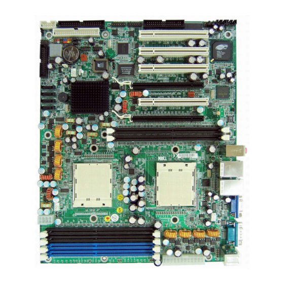
Page 9: Board Image
This picture is representative of the latest board revision available at the time of publishing. The board you receive may or may not look exactly like the above picture. The following page includes details on the vital components of this motherboard. http://www.tyan.com... -
Page 10: Block Diagram
2.2 - Block Diagram Tiger K8WE (S2877) Block Diagram http://www.tyan.com... -
Page 11: Board Parts, Jumpers And Connectors
This diagram is representative of the latest board revision available at the time of publishing. The board you receive may not look exactly like the above diagram. NOTE: * is only available on S2877ANRF version. ** is only available on S2877G2NR version. http://www.tyan.com... - Page 12 CPU1 Fan Connector (4pin) See Section 2.3.14 CPU2 Fan Connector (4pin) See Section 2.3.14 Chassis Fan Connector (4pin) See Section 2.3.15 J36/J10 Chassis Fan Connector (3pin) See Section 2.3.16 3-pin or 4-pin fan support See Section 2.3.17 selection Jumper http://www.tyan.com...
-
Page 13: Front Panel Header: J139
Power off system and disconnect both power connectors from the motherboard Use jumper cap to close Pin_1 and Pin_2 for several seconds to Clear CMOS Put jumper cap back to Pin_2 and Pin_3 (default setting) Reconnect power & power on system http://www.tyan.com... -
Page 14: Chassis Intrusion Header: J77
Note: For use with chassis that support this feature 2.3.4 *FireWire (IEEE1394A) Enable/Disable Jumper: *J147 Use this jumper to enable/disable IEEE1394. Open : Enable (Default) Closed : Disable Note: J147 is only available on S2877ANRF version. http://www.tyan.com... -
Page 15: Firewire (Ieee1394A) Pin Header: *J148/*J149
Note: J148 & J149 are only available on S2877ANRF version 2.3.6 Buzzer/External Speaker Header: J14 PIN1 Pin # Signal Description Speaker+ Buzzer- Speaker- Close Pin3 and Pin4 (Default) Enable onboard buzzer Open Pin3 and Pin4 Disable onboard buzzer or connect to chassis speaker http://www.tyan.com... -
Page 16: Com2 Connector: J42
1394 header. Both 1394 header and connector of 1394 cable are colored black. Please be aware that incorrect installation may harm the device. Note: Use these headers to connect to chassis front panel USB connectors. http://www.tyan.com... -
Page 17: Keyboard Lock Connector: J13
Closed : Disable 2.3.10 Gigabit LAN1/**LAN2 Front Panel Header: J2/ **J3 PIN1 Pin # Signal Description 1000Mb+/100Mb-_Link 1000Mb-/100Mb+_Link Active- Active+ Use this 4-Pin Header to connect LAN LED on Front Panel. Note: J3 is only available on S2877G2NR version. http://www.tyan.com... -
Page 18: Vga (Ati Rage Xl) Enable/ Disable Jumper: **J85
Note: J85 is only available on S2877G2NR version. 2.3.12 **BCM5705 Gigabit LAN Enable/ Disable Jumper: **J152 Open Closed Use this Jumper to enable/disable LAN2 (BCM5705 GbE LAN) Open : Enable (Default) Closed : Disable Note: J152 is only available on S2877G2NR version. http://www.tyan.com... -
Page 19: Front Panel Audio Header: *P53
Use these connectors to connect processor cooling fans to your motherboard. J9 for CPU1 & J37 for CPU2. This 4-pin fan connector supports a new standard fan with integrated fan speed control on the fan itself for better fan life. http://www.tyan.com... -
Page 20: Chassis 4-Pin Fan Connector: J47
2.3.16 Chassis 3-pin FAN Connectors: J36/J10 PIN1 Use these connectors to connect chassis cooling fans to your motherboard. The traditional 3-pin fan connector does not have PWM fan speed control function. http://www.tyan.com... -
Page 21: 3-Pin Or 4-Pin Fan Support Selection Jumper: J5
Signal Signal Description Description SYS_FAN_PWM CPU2_FAN_PWM CPU1_FAN_PWM Corresponding Pin # Connector 1 & 2 CPU1 FAN 3 & 4 CPU2 FAN 5 & 6 Chassis FAN Open: To support 3-pin auto fan Closed (Default): To support 4-pin auto fan http://www.tyan.com... -
Page 22: Installing The Processor(S)
CPU1. When using a single processor only CPU1 memory banks are addressable. TYAN is not liable for damage as a result of operating an unsupported configuration. The diagram is provided as a visual guide to help you install socket processors and may not be an exact representation of the processors you have. -
Page 23: Heatsink Retention Frame Installation
The following diagram will illustrate how to install the most common CPU back plates: 1. Mounting screws 2. Heatsink retention frame 3. CPU socket 4. Motherboard PCB 5. Adhesive insulator material 6. Backplate assembly NOTE: Please see next section for specific instructions on how to install mounting bracket. http://www.tyan.com... -
Page 24: Thermal Interface Material
CPU lid (applying too much will actually reduce the cooling). Always check with the manufacturer of the heatsink & processor to ensure the Thermal Interface material is NOTE compatible with the processor & meets the manufacturer’s warranty requirements http://www.tyan.com... -
Page 25: Heatsink Installation Procedures
2. After tightening screws secure metal clip to plastic retention bracket center tab. Repeat for the other side of heatsink. 3. After securing metal clip to plastic retention bracket center tab, push down on plastic clip to lock plastic clip to side tab. http://www.tyan.com... - Page 26 Repeat for other side. 2. Insert screw through metal clip. BE SURE METAL CLIP IS LOCKED ONTO RETENTION FRAME TAB. 3. Tighten screw through metal clip. Repeat on the other side. DO NOT OVER TIGHTEN. http://www.tyan.com...
-
Page 27: Finishing Installing The Heatsink
(which should already be attached to the heatsink) to the motherboard. The following diagram illustrates how to connect fans onto the motherboard. Once you have finished installing all the fans you can connect your drives (hard drives, CD-ROM drives, etc.) to your motherboard. http://www.tyan.com... -
Page 28: Tips On Installing Motherboard In Chassis
Some chassis’ include plastic studs instead of metal. Although the plastic studs are usable, TYAN recommends using metal studs with screws that will fasten the motherboard more securely in place. Below is a chart detailing what the most common motherboard studs look like and how they should be installed. -
Page 29: Installing The Memory
• 128MB, 256MB, 512MB, 1GB, 2GB and 4GB* Registered DDR400/333/266 DDR memory modules are supported • All installed memory will be automatically detected • The Tiger K8WE supports up to 24GB* with two CPU’s installed. * Not validated at time of print http://www.tyan.com... - Page 30 This following chart outlines the rules for populating memory (Note: X indicates a populated DIMM Slot) Memory Configuration Chart CPU1 CPU1 CPU1 CPU1 CPU2 CPU2 DIMM-A1 DIMM-A2 DIMM-B1 DIMM-B2 DIMM-A1 DIMM-A2 http://www.tyan.com...
- Page 31 To remove the memory module, simply push the latches outwards until the memory module pops up. Then remove the module. YOU MUST ALWAYS unplug the power connector from the motherboard before performing system hardware changes. NOTE Otherwise you may damage the board and/or expansion device. http://www.tyan.com...
-
Page 32: Attaching Drive Cables
Attaching Serial ATA Cables The Tiger K8WE is also equipped with 4 Serial ATA-II (SATAII) channels. Connections for these drives are also very simple. There is no need to set Master/Slave jumpers on SATA drives. http://www.tyan.com... - Page 33 Attach first floppy drive (drive A:) to the end of the cable with the twist in it. Drive B: is usually connected to the next possible connector on the cable (the second or third connector after you install Drive A:). http://www.tyan.com...
-
Page 34: Installing Add-In Cards
It is better to try another slot or return the faulty card rather than damaging both the motherboard and the add-in card. YOU MUST ALWAYS unplug the power connector from the motherboard before performing system hardware changes. NOTE Otherwise you may damage the board and/or expansion device. http://www.tyan.com... -
Page 35: Connecting External Devices
The chart below illustrates the different LED states. 10/100/1000 Mbps LAN Link/Activity LED Scheme Left LED Right LED Link Green 10 Mbps Active Blinking Green Link Green Green 100 Mbps Active Blinking Green Green Link Green Orange 1000 Mbps Active Blinking Green Orange No Link http://www.tyan.com... -
Page 36: Tips On Modifying I/O Shielding For Anrf And G2Nr Version
Please be aware that ATX 2.x and ATXGES power supplies are not compatible with the board and can damage the motherboard and/or CPU(s). EPS12V Main Power 24-Pin (Chipsets & Components) 12 12 12 +3.3V +12V2 +12V2 +5VSB PWR OK RESVD PSON# +3.3V -12V +3.3V +3.3V http://www.tyan.com... -
Page 37: Finishing Up
In the rare circumstance that you have experienced difficulty, you can find help by asking your vendor for assistance. If they are not available for assistance, please find setup information and documentation online at our website or by calling your vendor’s support line. http://www.tyan.com... - Page 38 http://www.tyan.com...
-
Page 39: Chapter 3: Bios
Use the left/right ( ) arrow keys to make a selection To display a sub-menu (A pointer “ ” marks all sub menus) Use the arrow keys to move the cursor to the sub menu you want. Then press <Enter>. http://www.tyan.com... -
Page 40: Bios Menu Bar
Execute command or select submenu 3.4 - Getting Help Pressing [F1] will display a small help window that describes the appropriate keys to use and the possible selections for the highlighted item. To exit the Help window, press [ESC] or [F1] key again. http://www.tyan.com... -
Page 41: Bios Main Menu
↑↓: Select Item F1: Help -/+: Change Values F9: Setup Defaults ← →: Select Screen Enter: Select Esc: Exit Sub-Menu F10: Previous Values Feature Option Description System Time HH:MM:SS Set the system time MM:DD: System Date Set the system date YYYY http://www.tyan.com... -
Page 42: Bios Advanced Menu
Choosing “Yes” will Secured Setup prevents a Plug and Play Configurations Operation System from changing system settings. Select “Yes” if you want to clear the Extended System Reset Configuration Data Configuration Data (ESCD) area. Hammer Configuration Menu Item Set Hammer Configuration. http://www.tyan.com... -
Page 43: Hammer Configuration Sub-Menu
Dram Bank Interleave [Disabled] Large Memory Simulation: [200 Mhz] HT-LDT Frequency: [Discrete] MTRR Mapping [Disabled] ACPI SRAT Table ↑↓: Select Item F1: Help -/+: Change Values F9: Setup Defaults ← →: Select Screen Enter: Select Esc: Exit Sub-Menu F10: Previous Values http://www.tyan.com... -
Page 44: Integrated Devices Sub-Menu
<Minus> keys to change the value of the selected option. PhoenixBIOS Setup Utility Advanced USB Control [Disabled] Item Specific Help USB BIOS Legacy Support: [Disabled] [Enabled] MAC LAN Bridge: XXXXXXXXXXXXX MAC Address [Enabled] SATA0 Controller [Enabled] SATA1 Controller [PIC] Interrupt Mode: NV RAID Configuration http://www.tyan.com... - Page 45 You can use this screen to select options for the NV Configuration settings. Use the up and down <Arrow> keys to select an item. Use the <Plus> and <Minus> keys to change the value of the selected option. PhoenixBIOS Setup Utility Advanced NV Configuration [Disabled] Item Specific Help http://www.tyan.com...
-
Page 46: Pci Configuration Sub-Menu
Use the up and down <Arrow> keys to select an item. Use the <Plus> and <Minus> keys to change the value of the selected option. PhoenixBIOS Setup Utility Advanced Note PCI Slot Layout Convention in Help Window Item Specific Help http://www.tyan.com... - Page 47 You can use this screen to select options for the PCI Device, Slot # 1 & 2 settings. Use the up and down <Arrow> keys to select an item. Use the <Plus> and <Minus> keys to change the value of the selected option. PhoenixBIOS Setup Utility Advanced http://www.tyan.com...
- Page 48 You can use this screen to enable/disable Onboard Device (BroadCom NIC and IEEE1394 Controller) and their Option ROMs . PhoenixBIOS Setup Utility Advanced BCM5705 LAN [Enabled] Item Specific Help BCM5705 LAN OPROM [Enabled] IEEE1394 Controller [Enabled] Onboard VGA [Enabled] Default Primary Video Adapter [Add On] http://www.tyan.com...
- Page 49 F9: Setup Defaults ← →: Select Screen Enter: Select Esc: Exit Sub-Menu F10: Previous Values Feature Option Description C800-CBFF, CC00-CFFF Reserves the specified Available D000-D3FF, D400-D7FF block of upper memory for Reserved D800-D8FF, DC00-DFFF use by legacy ISA devices. http://www.tyan.com...
- Page 50 ↑↓: Select Item F1: Help -/+: Change Values F9: Setup Defaults ← →: Select Screen Enter: Select Esc: Exit Sub-Menu F10: Previous Values Feature Option Description Reserves the specified IRQ Available IRQ3/4/5/7/9/10/11/15 for use by legacy ISA Reserved devices. http://www.tyan.com...
-
Page 51: Ide Configuration Sub-Menu
Disabled SMART Device Monitoring IDE failure prediction. Enabled Both Disabled Enable the integrated local Local Bus IDE adapter bus IDE adapter. Primary Secondary Primary Master/Slave Menu Item Configure the IDE channel. Secondary Master/Slave Menu Item Configure the IDE channel. http://www.tyan.com... - Page 52 Enabled Cylinders, Heads_Sectors. This setting enables or Disabled 32 Bit I/O disables 32 bit IDE data Enabled transfers. Select the method for Standard Transfer Mode moving data to/from the Fast PIO 1 drive. http://www.tyan.com...
-
Page 53: Floppy Configuration Sub-Menu
↑↓: Select Item F1: Help -/+: Change Values F9: Setup Defaults ← →: Select Screen Enter: Select Esc: Exit Sub-Menu F10: Previous Values Feature Option Description Disabled Legacy Diskette A/B Select floppy type Enabled http://www.tyan.com... -
Page 54: I/O Device Configuration Sub-Menu
Set the interrupt for serial Interrupt IRQ4 port A. Disabled Configure serial port B Serial port B using options. Enabled Normal Set the mode for Serial Mode port B using options. Set the base I/O address Base I/O address for serial port B. http://www.tyan.com... -
Page 55: Hardware Monitor Sub-Menu
System Fan Speed xxxxRPM CPUx VDD Voltage x.x V +12V x.xV x.xV +3.3V x.xV CK804 Vcore x.xV ↑↓: Select Item F1: Help -/+: Change Values F9: Setup Defaults ← →: Select Screen Enter: Select Esc: Exit Sub-Menu F10: Previous Values http://www.tyan.com... -
Page 56: Console Redirection Sub-Menu
Com Port Address COMA address. On-board COMB 19200 38400 Enable the specified baud Baud Rate rate. 57600 115200 VT100 VT100, 8bit PC-ANSI,7bit Enable the specified Console Type console type. PC ANSI VT100+ VT-UTF8 None Flow Control Enable flow control. XON/XOFF http://www.tyan.com... -
Page 57: Watchdog Timer Option Sub-Menu
F1: Help -/+: Change Values F9: Setup Defaults ← →: Select Screen Enter: Select Esc: Exit Sub-Menu F10: Previous Values Feature Option Description disabled Enable/disable Watchdog Watchdog Timer Timer enabled Watchdog Time_Out Time_Out Minutes 1~255 configuration in Minutes(1- 255) http://www.tyan.com... -
Page 58: Bios Memory Menu
Cache E000 – E3FF: [Disabled] Cache E400 – E7FF: [Disabled] Cache E800 – E8FF: [Disabled] Cache EC00 – EFFF: ↑↓: Select Item F1: Help -/+: Change Values F9: Setup Defaults ← →: Select Screen Enter: Select Esc: Exit Sub-Menu F10: Previous Values http://www.tyan.com... -
Page 59: Security Menu
[Normal] Fixed disk boot sector: [User] Diskette access: [Disabled] Virus check reminder: [Disabled] System backup reminder: ↑↓: Select Item F1: Help -/+: Change Values F9: Setup Defaults ← →: Select Screen Enter: Select Esc: Exit Sub-Menu F10: Previous Values http://www.tyan.com... -
Page 60: Bios Boot Menu
[Disabled] QuickBoot Mode: Item Specific Help [Disabled] Boot-time Diagnostic Screen [Disabled] Summary screen Boot Device Priority ↑↓: Select Item F1: Help -/+: Change Values F9: Setup Defaults ← →: Select Screen Enter: Select Esc: Exit Sub-Menu F10: Previous Values http://www.tyan.com... -
Page 61: Boot Device Priority
← →: Select Screen Enter: Select Esc: Exit Sub-Menu F10: Previous Values The boot menu will list all bootable devices. Use <Enter> to expand or collapses devices with a ‘+’ or ‘-‘. Use <+> or <-> to arrange the priorities of all bootable devices. http://www.tyan.com... -
Page 62: Power Menu
Enable will let power button possible to shutdown the system in legacy OS without holding for 4 Power Button Off Disable seconds. Disable will force 4 second power button to shutdown the system. Spread Spectrum Disabled Enable or disable Spread http://www.tyan.com... - Page 63 Enable Spectrum. Stay Off Power Loss Control Control power loss. Power On http://www.tyan.com...
-
Page 64: Bios Exit Menu
Discard Changes Use this option to restore all new setup values that you have made but not saved in CMOS. Save Changes Use this option to restore all new setup values that you have made and saved in CMOS. http://www.tyan.com... - Page 65 http://www.tyan.com...
-
Page 66: Chapter 4: Diagnostics
BIOS flash failure, you must contact your dealer for a replacement BIOS. There are no exceptions. TYAN does not have a policy for replacing BIOS chips directly with end users. In no event will TYAN be held responsible for damages done by the end user. -
Page 67: Bios Post Code
Enable A20 line Test RAM between 512 and 640 KB Autosize DRAM Test extended memory Initialize POST Memory Test extended memory Manager address lines Clear 512 KB base RAM Jump to UserPatch1 1-3-4-1. RAM failure on Configure advanced cache address registers http://www.tyan.com... - Page 68 Test and initialize PS/2 Initialize error logging mouse Initialize floppy controller Initialize error display function Determine number of ATA Initialize system error drives (optional) handler Initialize hard-disk PnPnd dual CMOS controllers (optional) Initialize local-bus hard-disk Initialize notebook docking controllers (optional) http://www.tyan.com...
- Page 69 Initialize PIC and DMA Initialize System Management Mode Initialize Memory type Output one beep before boot Initialize Memory size Boot to Mini DOS Shadow Boot Block Clear Huge Segment System memory test Boot to Full DOS Initialize interrupt vectors http://www.tyan.com...
-
Page 70: Glossary
The CPU can manipulate data in a buffer before copying it to a disk drive. While this improves system performance (reading to or writing from a disk drive a single time is much faster than doing so repeatedly) there is the possibility of http://www.tyan.com... - Page 71 CPU. This frees up CPU resources for other tasks. As with IRQs, it is vital that you do not double up devices on a single line. Plug-n-Play devices will take care of this for you. http://www.tyan.com...
- Page 72 BIOS, it is a ROM chip which can, unlike normal ROM, be updated. This allows you to keep up with changes in the BIOS programs without having to buy a new chip. TYAN’s BIOS updates can be found at http://www.tyan.com ESCD (Extended System Configuration Data): a format for storing information about Plug-n-Play devices in the system BIOS.
- Page 73 PnP (Plug-n-Play): a design standard that has become ascendant in the industry. Plug-n-Play devices require little set-up to use. Devices and operating systems that are not Plug-n-Play require you to reconfigure your system each time you add or change any part of your hardware. http://www.tyan.com...
- Page 74 AcceleRAID 150, 200 or 250, to implement RAID on a system board-embedded SCSI bus or a set of SCSI busses. SISL: SCSI Interrupt Steering Logic ( LSI ) (only on LSI SCSI boards) Sleep/Suspend mode: in this mode, all devices except the CPU shut down. http://www.tyan.com...
- Page 75 CPUs without damaging the sensitive CPU pins. The CPU is lightly placed in an open ZIF socket, and a lever is pulled down. This shifts the processor over and down, guiding it into the board and locking it into place. http://www.tyan.com...
-
Page 76: Technical Support
Return Merchandise Authorization (RMA) number. The RMA number should be prominently displayed on the outside of the shipping carton and the package should be mailed prepaid. TYAN will pay to have the board shipped back to you. http://www.tyan.com... - Page 77 Danger of explosion if battery is incorrectly replaced. Replace only with the same or equivalent type recommended by manufacturer. Dispose of used battery according to manufacturer instructions and in accordance with your local regulations. Document #: D1681-101 http://www.tyan.com...
Need help?
Do you have a question about the Tiger K8WE S2877 and is the answer not in the manual?
Questions and answers