Advertisement
HD07-S/HD09/HD09-S/HD20/
HD30/HD3N/HD50 Series
Simple Manual
This manual is only for simple description.
For more detailed information, please refer to the
user manual of each product.
Please visit www.hpmont.com to download.
A Danger Information which is Critical for Avoiding Safety Hazard
• Electrical installation must be performed by a qualified electrical
Danger
engineer and maintained by a professionally trained and authorized
professional.
• The inverter should be installed on a flame-retardant object such as
metal, away from flammable and explosive objects.
• After the inverter is powered o for 10 minutes, confirm that the
internal charge indicator is o and the voltage between the power
terminals (+) and (-) is lower than 36V, only then can operate.
• After the external power emergency stop terminal is turned on, be
sure to confirm that its action is e ective and reliable.
• The inverter has a leakage current greater than 3mA to the ground.
The specific value is determined by the use conditions. The inverter
and the motor must use two independent grounding wires to ensure
safety. It is also recommended that users install Type B leakage
protection devices (ELCB/RCD).
• Before starting the motor and mechanical equipment, please make
sure that the motor and mechanical equipment are working within
the allowable range.
• Please note that do not touch the inverter terminals when the inverter
is powered. Do not connect the power terminals of the inverter to the
product housing, and do not short-circuit the power terminals.
• When the operating environment exceeds 40℃ , the inverter needs to
be derated. For every 1℃ increase, it needs to be derated by 2%. The
Max. working environment temperature is 50℃ .
• When the altitude exceeds 1000 meters, derating is required.
A Warning Information which is Critical for Avoiding Damage to the
Product and other Device
Warning
• Do not drop wires, screws, or drilling residue into the inverter during
installation work.
• The inverter has passed the withstand voltage test before leaving the
factory, so it can not be tested again.
• For products stored for more than 2 years, the power supply shall be
boosted slowly through the voltage regulator when power on.
• Please tighten the terminal reliably.
• Do not connect the input power line to the output U/V/W terminal.
• Do not connect the phase shift capacitor to the output loop.
• Switch the motor or perform variable frequency/power frequency
switching when the inverter stops outputting.
• Do not short-circuit the inverter DC bus terminals.
Safety Information
V1.2 2021.10
Advertisement
Table of Contents

Related Manuals for hpmont HD50 Series


Summarization of Contents
Safety Information
General Safety Hazards
Critical information for avoiding safety hazards during installation and operation.
Product Damage Warnings
Precautions to prevent damage to the product and other devices.
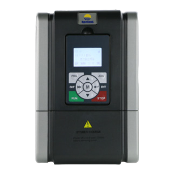
Keypad Overview
Keypad Layout and Functions
Describes the layout and function of each key on the inverter keypad.
Keypad Management
Keypad Removal and Installation
Instructions for removing and installing the keypad unit.
External Keypad Connectivity
Details on connecting the keypad externally via RJ45 ports.
Electrical Installation Basics
Cover Removal Procedures
Steps for removing the inverter's protective cover for wiring.
Electrical Installation Details
Terminal Wiring Diagram
Visual representation of terminal connections for power and control circuits.
Power Terminal Descriptions
Explains the function of each power input and output terminal.
Control Terminal Layout
Details the available control terminals for various models.
Encoder Card Specifications
Information on the standard encoder card for HD50 products.
Function Parameters - Status and Basic
Status Display Parameters
Parameters for monitoring inverter status and operating values.
Basic Function Parameters
Core parameters for motor control, frequency, and command settings.
Function Parameters - Advanced
PID Control Parameters
Settings for proportional, integral, and derivative control loops.
Motor and Encoder Parameters
Parameters related to motor characteristics and encoder feedback.
Function Parameters - I/O and Detection
Digital and Analog I/O Terminal Settings
Configuration of digital and analog input/output terminals.
Function Parameters - Communication and Faults
Communication Parameters
Settings for data format and baud rate for communication.
Fault Log Parameters
Parameters related to storing and displaying fault information.
Troubleshooting Common Faults
Power On and Voltage Faults
Addresses issues like no display, undervoltage, and overvoltage.
Overcurrent and Overload Faults
Solutions for inverter overcurrent and motor overload errors.
System Component Faults
Troubleshooting for power module, heatsink, brake unit, and CPU faults.
Troubleshooting Advanced Faults
Output and Motor Faults
Diagnosing output offload, motor overload, and overheat issues.
Communication and Encoder Faults
Resolving issues related to communication timeouts and encoder errors.
Quick Start Guide
Motor Parameter Setup
Essential motor parameters to configure before operation.
Keypad Control Mode
How to use the keypad for starting, stopping, and setting frequency.
Quick Start Guide - Terminal Control
Terminal Control Mode
Using terminals for start/stop and analog frequency setting.
Communication Control Mode
Controlling operation via SCI communication.
Need help?
Do you have a question about the HD50 Series and is the answer not in the manual?
Questions and answers