Table of Contents
Advertisement
Quick Links
Advertisement
Table of Contents

Related Manuals for hpmont HD20 Series


Summary of Contents for hpmont HD20 Series
- Page 1 HD20 Series Multi-function Inverter User Manual V1.9 2020.03...
- Page 2 Thank you for purchasing HD20 series multi-function inverter manufactured by Shenzhen Hpmont Technology Co., Ltd. This User Manual describes how to use HD20 series inverters and their installation wiring, parameter setting, troubleshooting and daily maintenance etc. Before using the product, please read through this User Manual carefully. In addition, please do not use this product until you have fully understood safety precautions.
- Page 3 Connection with peripheral devices Three-phase AC power supply MCCB Contactor AC input reactor (accessory) EMI filter Braking resistor Inverter (accessory) STOP EMI filter AC output reactor (accessory) Motor...
- Page 4 Version and Revision Records Time: 2020/3 Version: V1.9 Revised Chapter Revised Contents Chapter 6 • F15.00 - F15.05 added function: Appendix A • 83: Integration keeping function • 84: Direct input of DC braking • F15.39 added function: • Hundred: Analog overrun detection conditions •...
- Page 6 Quick Start for HD20 Operation Note: Some parameters have been set (factory setting) so that you could not set for the initial use. 1. Set the Motor Rating Parameter Correctly Power on, use keypad to set the following parameters, motor parameters refer to motor nameplate. Ref.
- Page 7 3. Control the Start/Stop Via Terminals and Set the Running Frequency Via Keypad 1. The terminal DI1 is forward running signal input, and DI2 is reverse running signal input, their wirings are as following figure. Output indicating Forward signal at running Reverse Fault indicating 2.
- Page 8 4. Control the Start/Stop Via Terminals and Set the Running Frequency Via Analogue 1. The terminal DI1 is forward running signal input, and DI2 is reverse running signal input, their wirings are as following figure. Forward Output indicating Reverse signal at running Fault indicating Analogue input 2.
- Page 9 5. Control the Start/Stop Via Terminals and Set the Running Frequency Via Communication 1. The terminal DI1 is forward running signal input, and DI2 is reverse running signal input, their wirings are as following figure. Forward Output indicating signal at running Reverse Fault indicating MODBUS...
- Page 10 6. Control the Start/Stop and Set the Running Frequency Via Using Communication 1. The communication wirings are as following figure. Output indicating signal at running MODBUS Fault indicating 2. After power on, set the functional parameters in accordance with wirings, as following table. Ref.
- Page 11 7. Motor Parameter Auto-tuning 1. Motor parameter auto-tuning can be only done in keypad mode. 2. Correct wiring. 3. Power on, set motor parameter (F08.00 - F08.04) by keypad. 4. Parameter auto-tuning, available auto-tuning methods for different control mode are shown as below table.
- Page 12 8. Input/output Parameter Setting for Analogue AI and AO Current 4 - 20mA Analogue 4 - 20mA Input Current inputs through AI2. Default current: 0 - 20mA. Short connect pin 2&pin 3 of CN4. To use 4 - 20mA signal to adjust frequency 0 - 50Hz, set parameters according to following: Method Ref.
-
Page 14: Table Of Contents
CONTENTS Chapter 1 Safety Information and Precautions ....................1 1.1 Safety Definition ..........................1 1.2 About Motor and Load ........................1 1.3 About HD20 ............................2 Chapter 2 Product Information ..........................5 2.1 Model Code Explanation ......................... 5 2.2 Nameplate ............................5 2.3 Rated Value ............................ - Page 15 4.5.4 Ground Connection........................... 28 4.5.5 EMI Filter ................................ 28 4.5.6 Countermeasures for Conduction, Radiation and Radio Frequency Interference ....29 4.5.7 Reactor ................................29 Chapter 5 Operation Instructions ......................... 31 5.1 Function Description ........................31 5.1.1 Operation Mode ............................31 5.1.2 Inverter Frequency Setting Source ......................
- Page 16 6.3 Group y Manufacturer Function Parameters................90 Chapter 7 Troubleshooting and Maintenance ....................91 7.1 Troubleshooting ..........................91 7.2 Maintenance ............................ 94 Chapter 8 Options ..............................97 8.1 Panel Installation Assembly ......................97 8.2 Braking Resistor ..........................98 Appendix A Parameters ............................99 Appendix B Communication Protocol .......................
- Page 18 Safety Information and Precaution Product Information Mechanical Installation Electrical Installation Operation Instructions Function Introduction Troubleshooting and Maintenance Options Parameters Communication Protocol...
-
Page 20: Chapter 1 Safety Information And Precautions
1.2 About Motor and Load Compared to the Standard Frequency Operation The HD20 series inverters are voltage-type frequency inverter and their output is PWM wave with certain harmonic wave. Therefore, the temperature, noise and vibration of the motor will be a little higher than that at standard frequency operation. -
Page 21: About Hd20
HD20 that is powered, please cut off the AC power supply for more than 10 minutes, confirm the internal charge indicator is off and the voltage between (+) and (-) of the main circuit terminals is below 36V. - 2 - HD20 Series User Manual V1.9... - Page 22 Chapter 1 Safety Information and Precautions Generally, the internal circuit enables the capacitor to discharge. However, the discharging may fail in some exceptions. In these cases, users need to consult Hpmont or our regional distributor. Change Three-phase Input to Single-phase Input For three-phase input inverter, the users should not change it to single-phase input.
-
Page 24: Chapter 2 Product Information
1 0 min s Product model MODEL: HD20-4T5P5G Motor power 5.5kW POWER: Input specification INPUT: 3PH 380-460V 15A 50/60Hz Output specification OUTPUT: 8.5kVA 0-460V 13A 0-400Hz Software version Version: 1.00 Serial number HD20 Series User Manual V1.9 - 5 -... -
Page 25: Rated Value
Speed resulotion Analogue setting: 0.1% × max-frequency Speed control accuracy SVC: ±0.5% Speed control range SVC: 1:100 Torque control response SVC: <200ms Start torque SVC: 180% rated torque/0.5Hz Torque control accuracy ±5% - 6 - HD20 Series User Manual V1.9... - Page 26 DI1 - DI6, DI6 can be selected as high-speed pulse signal Digital output DO1, DO2, DO2 can be selected as high frequency pulse signal output Programmable relay R1A/R1B/R1C: Contact rating 250VAC/3A or 30VDC/1A output SCI communication RJ45 interface HD20 Series User Manual V1.9 - 7 -...
- Page 27 CAN option [HDFB-CAN] Status keypad [HD-LED-L] Small-size keypad [HD-LED-P-S] LCD keypad [HD-LED] About keypad LCD keypad [HD-LCD] Mounting base to keypad [HD-KMB] Small-size external mounting base [HD-KMB-S] 1m/2m/3m/6m extension cable to keypad [HD-CAB-1M/2M/3M/6M] - 8 - HD20 Series User Manual V1.9...
-
Page 28: Parts Of Inverter
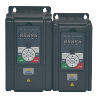
Chapter 2 Product Information 2.5 Parts of Inverter Mounting hole Keypad Upper enclosure Bottom enclosure Potentiometer Connection holes of control terminal Certification PR G Connection holes STOP of power terminal Nameplate Terminal cover HD20 Series User Manual V1.9 - 9 -... -
Page 30: Chapter 3 Mechanical Installation
HD20 shall be 2% for each degree centigrade. Max. allowed temperature is 50 ℃ 2. Keep ambient temperature between -10 - +40 . It can improve the running performance if install at location with good ventilation or cooling devices. HD20 Series User Manual V1.9 - 11 -... -
Page 31: Installation Direction And Space Requirements
3.3 Installation Direction and Space Requirements To achieve good cooling efficiency, install the inverter perpendicularly and always provide the following space to allow normal heat dissipation. HD20 series inverters can be mounted in parallel, shown in Figure 3-1. ≥100mm LO/RE... -
Page 32: Dimensions And Mounting Size
LO/RE LOCK STOP Figure 3-3 Dimensions of HD20 inverter Table 3-1 HD20 dimensions Dimension (mm) Mounting size (mm) Model (kg) HD20-2S0P2G HD20-2S0P4G HD20-2D0P7G HD20-2D1P5G HD20-4T0P4G HD20-4T0P7G HD20-4T1P5G HD20-2D2P2G HD20-4T2P2G HD20-4T3P0G HD20-4T4P0G HD20-4T5P5G HD20 Series User Manual V1.9 - 13 -... -
Page 33: Install And Dismantle Keypad
There are two steps in Figure 3–5. First, press the hook of the keypad according to direction 1. Second, take out of the keypad according to direction 2. STOP Figure 3–5 Dismantle keypad - 14 - HD20 Series User Manual V1.9... -
Page 34: Dismantle Plastic Cover
Chapter 3 Mechanical Installation 3.6 Dismantle Plastic Cover The upper cover and the lower cover of the HD20 series inverter are removable. The dismantle step is shown as Figure 3-6. Before removing the upper cover, please take away the keypad. -
Page 36: Chapter 4 Electrical Installation
MCCB (molded case circuit breaker) or equivalent device. The recommended specification of MCCB, contactor & cables are shown as Table 4-1. The size of ground wire should accord with the requirement in 4.3.5.4 of IEC61800-5-1. HD20 Series User Manual V1.9 - 17 -... -
Page 37: Power Terminal Lug
4.3 Main Circuit Terminals and Wiring Danger • The bare portions of the power cables must be bound with insulation tapes. Warning • Ensure that AC supply voltage is the same as rated input voltage of HD20. - 18 - HD20 Series User Manual V1.9... -
Page 38: Supply And Motor Terminal
Refer to section 8.2 Braking Resistor (on page 98) for braking resistor and unit. L1 L2 (+) (-) EMI filter Braking AC reactor resistor Supply ground MCCB Contactor Mains supply Figure 4-1 Supply and motor connection HD20 Series User Manual V1.9 - 19 -... -
Page 39: Control Board
Programmable bipolar optional input signal Input voltage: 0 - 30VDC DI1 - DI6 Digital input DI1 - DI5 input impedance: 4.7kW, DI6 input impedance: 1.6kΩ • DI6 can be selectable for high-frequency input, max-frequency 50kHz - 20 - HD20 Series User Manual V1.9... -
Page 40: Jumper
• Pin 2&3 are short-connected, AO1 outputs current signal. AO2 can select voltage or current signal. • Pin 1&2 are short-connected, AO2 outputs voltage signal (factory setting). • Pin 2&3 are short-connected, AO2 outputs current signal. HD20 Series User Manual V1.9 - 21 -... -
Page 41: Communication Terminal
Input terminal 3 Output terminal 2 HD20 Input terminal 4 Control Board Input terminal 5 Input terminal 6 Relay output 1 Analogue output 1 Analogue output 2 Figure 4-4 HD20 control board connection - 22 - HD20 Series User Manual V1.9... - Page 42 Using external power supply, the source/drain connection are shown in Figure 4-6 (remove the connector between SEL and P24). +24V +24V 12 - 30V 12 - 30V Drain Source Using external Using external power supply power supply Figure 4-6 Source/Drain connection when using external power HD20 Series User Manual V1.9 - 23 -...
- Page 43 Figure 4-8. Selecting +/-10V external supply, refer to Figure 4-9. AI2 are selected as current input and the range is 0 - 20mA, refer to Figure 4-9. External power supply +10V -10V Figure 4-9 AI2 connection - 24 - HD20 Series User Manual V1.9...
- Page 44 DO2 is pulse frequency output; DO2 can use internal 24V power supply of inverter or external power supply. The connection is shown in Figure 4-11. +24V +24V R: 10kΩ pull-up resistor f: Digital frequency meter 12 - 30V Figure 4-11 DO2 connection HD20 Series User Manual V1.9 - 25 -...
-
Page 45: Meet Emc Requirement Of Installation
• EMI filters should be installed at the interfaces between different areas if necessary. • Bus cable (such as RS485) and signal cable must be shielded. - 26 - HD20 Series User Manual V1.9... -
Page 46: Wiring Requirement
The controller should be derated if motor cables are too long or their CSA is too large. The current should be decreased by 5% when per level of CSA is increased. If the CSA increase, so do the current to ground and capacitance. HD20 Series User Manual V1.9 - 27 -... -
Page 47: Ground Connection
When the frequency is high, so is the impedance of cable, hence there is little bypass effect. - 28 - HD20 Series User Manual V1.9... -
Page 48: Countermeasures For Conduction, Radiation And Radio Frequency Interference
When the length of cable between inverter and motor is more than 100m, it will cause leakage current and controller tripping. It is suggested that user should consider installing an AC output reactor. HD20 Series User Manual V1.9 - 29 -... -
Page 50: Chapter 5 Operation Instructions
Control terminals Use the control terminal to start the inverter and stop the operation control. SCI communicaiton Through the SCI communication drive start, stop running control. HD20 Series User Manual V1.9 - 31 -... -
Page 51: Inverter Frequency Setting Source
• The simple PLC operation mode can be paused by the DI terminal (function No. 30). Wobble F07.00 = 1, the inverter will run in accordance with the pre-set operating parameters (see F07 operation group parameter). - 32 - HD20 Series User Manual V1.9... -
Page 52: Operating Instructions
V The unit of the present The present parameter is Rotary speed unit parameter is rpm rotary speed unit The unit of the present % unit function parameter is % HD20 Series User Manual V1.9 - 33 -... -
Page 53: Display Status
Figure 5-1. Other parameters (F18.08 - F18.13) or F18.02 - F18.07 can be displayed by pressing LO/RE LOCK LO/RE LOCK Figure 5-1 Display status of stop (left) and run (right) - 34 - HD20 Series User Manual V1.9... - Page 54 Copy para. to keypad Failed to copy para Reset LO/RE LOCK LO/RE LOCK LO/RE LOCK LO/RE LOCK Initializing keypad self-check success DC bus under-voltage keypad self-check error Figure 5-4 Special display status HD20 Series User Manual V1.9 - 35 -...
-
Page 55: Keypad Operation Examples
Increase Increase by 1 according Increase by 1 when press by 1 according to the to the present modified Cycle according to d- this key one time present modified bit F-U-y - 36 - HD20 Series User Manual V1.9... - Page 56 • The function parameter can’t be modified, such as the actual detected parameters or recorded parameters etc. • Only when the controller stops can the function parameter be modified. • Only input the correct password can it edit the function parameter due to the valid password. HD20 Series User Manual V1.9 - 37 -...
- Page 57 The operation of unlock user’s password is as shown in Figure 5-8 which takes 4 as the user’s password. LO/RE LOCK LO/RE LOCK LO/RE LOCK Third-level menu Fourth-level menu Set password LO/RE LOCK LO/RE LOCK 1.5s later Third-level menu Unlock password success Figure 5-8 Operation of unlocking user’s password - 38 - HD20 Series User Manual V1.9...
- Page 58 “F01.01”, clear the user’s password according to Figure 5-10. LO/RE LOCK LO/RE LOCK LO/RE LOCK Third-level menu Third-level menu Fourth-level menu LO/RE LOCK LO/RE LOCK 1.5s later Third-level menu Clear password success Figure 5-10 Operation of clearing user’s password HD20 Series User Manual V1.9 - 39 -...
-
Page 59: Initial Power On
After checking the wiring and mains supply voltage, switch on the circuit breaker and the inverter will be initialization. The keypad will display as shown in Figure 5-13. LO/RE LOCK LO/RE LOCK LO/RE LOCK Firstly display Then display Stop status Figure 5-13 Display initialing keypad - 40 - HD20 Series User Manual V1.9... -
Page 60: Chapter 6 Function Introduction
F19: Function-boost Parameters (on pages 81 - 87) F20: Protection of Fault Parameters (on pages 87 - 90) F23: PWM Control Parameters (on pages 90 - 90) Manufacturer Function Parameters (on page 90) HD20 Series User Manual V1.9 - 41 -... -
Page 61: Group D: Display Parameters
Master setting frequency source [Actual value] Display the master setting frequency source, see parameter F00.10. d00.12 Master setting frequency (Hz) [Actual value] d00.13 Auxiliary setting frequency (Hz) [Actual value] d00.14 Setting frequency (Hz) [Actual value] - 42 - HD20 Series User Manual V1.9... - Page 62 Process PID integral item (%) [Actual value] Display process PID integral item relative to full scale (10.00V) percentage. d00.48 Process PID output (%) [Actual value] Display process PID output to full scale (10.00V) percentage. HD20 Series User Manual V1.9 - 43 -...
- Page 63 High bit of energy consumption at this time running (k km.h) [Actual value] d00.60 Low bit of energy consumption at this time running (km.h) [Actual value] d00.61 Present fault [Actual value] Display the present fault. Displaying 100 means the undervoltage. - 44 - HD20 Series User Manual V1.9...
-
Page 64: Group F: General Function Parameters
4: Terminal pulse setting. It is set by the terminal pulse DI6. • Refered to group F05 for the corresponding relationship between the pulse terminal frequency and the inverter’s running frequency setting. HD20 Series User Manual V1.9 - 45 -... - Page 65 Jog running of jog operation set by F00.16. frequency Time • After the interval of jog is completed, it immediately execute the arrived jog F00.16 command. As show in figure. Jog command Time - 46 - HD20 Series User Manual V1.9...
- Page 66 0: Enabled. When the inverter connects to two keypads, the keys of optional display using the communication port can be operated. 1: Invalid. When the inverter connects to two keypads, the keys of optional display using the communication port can not be operated. HD20 Series User Manual V1.9 - 47 -...
-
Page 67: F01: Protection Parameters
1,2: Upload the current function code settings to the keypad EEPROM parameter 1/2. Upload Present setting Note: F01.00, F01.02, F01.03, F20.21 - F20.37 and group y can not be copied. function parameter F01.03 = 1 / 2 Inverter - 48 - HD20 Series User Manual V1.9... -
Page 68: F02: Run/Stop Control Parameters
0.00 - 10.00 [0.00s] When the inverter receives the run command, it will wait for the delay time set by F02.01 and then start running. F02.02 Start DWELL frequency setting 0.00 - upper limit [0.00Hz] HD20 Series User Manual V1.9 - 49 -... - Page 69 V/f ratio of speed search = F02.11 × motor’s rated voltage / motor’s rated frequency. F02.12 Disposal time after speed search 0.01 - 5.00 [1.00s] Complete the establishment of the time from searching the frequency to output the voltage in speed search process. - 50 - HD20 Series User Manual V1.9...
- Page 70 DC braking value stop. Time F02.18 = 0.00s, there is no DC braking process at stop. F02.17 F02.18 • Only when F02.13 = 2 will F02.16 - F02.18 be Run command enabled. HD20 Series User Manual V1.9 - 51 -...
-
Page 71: F03: Acc./Dec. Parameters
0.01 - 600.00 [6.00s] F03.15 and F03.16 define the Acc./Dec. time of jog operation. F03.17 Deceleration time of emergency stop 0.01 - 600.00 [10.00s] It defines the deceleration time of emergency stop. - 52 - HD20 Series User Manual V1.9... -
Page 72: F04: Process Pid Control
F04.08 defines the process PID differential amplitude limit value. F04.09 defines the sampling cycle of feedback value and the PID regulator calculates once in each sampling cycle. • When F04.07 = 0, the differential is disabled. HD20 Series User Manual V1.9 - 53 -... - Page 73 It defines the PID upper limit frequency when reverse. • When F04.18 = 1 (PID regulation enable reverse), it is enabled. F04.23 PID mode selection 0 - 2 [0] 0: NO PID mode. 1: Reserved. 2: PID enhancement mode. - 54 - HD20 Series User Manual V1.9...
-
Page 74: F05: External Reference Curve Parameters
Positive and negative characteristic of line Setting Setting corresponding value corresponding value F05.04 F05.02 F05.08 F05.06 F05.02 F05.04 P/A(setting) P/A(setting) F05.06 F05.08 F05.01 F05.03 F05.01 F05.03 F05.05 F05.07 F05.05 F05.07 HD20 Series User Manual V1.9 - 55 -... - Page 75 • Frequency setting is uncontinuous, while frequency output is continuous. F05.21 Jog operation frequency digital setting 2 0.00 - upper limit [5.00Hz] When select jog operation 2 through terminal, set the jog frequency operation according to F05.21. - 56 - HD20 Series User Manual V1.9...
-
Page 76: F06: Ms Speed And Simple Plc
• 1: Maintain the final value after single cycle of PLC operation. The inverter will maintain the run frequency and direction of the last step after completing one operating cycle. Keep T4 T5 T7 T8 T9 T11 T12 T13 T14 Running command HD20 Series User Manual V1.9 - 57 -... - Page 77 000 - 321 [000] F06.23 Setting of PLC step 4 000 - 321 [000] F06.25 Setting of PLC step 5 000 - 321 [000] F06.27 Setting of PLC step 6 000 - 321 [000] - 58 - HD20 Series User Manual V1.9...
- Page 78 F06.46 define the running time of PLC at different steps. • When set the running time to 0 at some step, it means that the PLC function of this step is disabled. HD20 Series User Manual V1.9 - 59 -...
-
Page 79: F07: Wobble Operation Parameters
Thousand: Save the wobble operation parameters at power outage • 0: Saved. When the hundreds of F07.01 is set as 0, the wobble operation parameters will be saved when power outage occurs. • 1: Not be saved. - 60 - HD20 Series User Manual V1.9... -
Page 80: F08: Asynchronous Motor Parameters
Rated RPM of motor 1 - 24000 [1500rpm] F08.03 and F08.04 should be set in accordance with the parameters of motor nameplate. F08.05 Power factor of motor 0.001 - 1.000 [Depend on HD20] HD20 Series User Manual V1.9 - 61 -... - Page 81 Leakage inductance of motor 0 - 9999mH [Depend on HD20] F08.10 Mutual inductance of motor 0 - 5000mH [Depend on HD20] F08.11 Idling exciting current of motor 0.0 - 999.9A [Depend on HD20] - 62 - HD20 Series User Manual V1.9...
-
Page 82: F09: V/F Control Parameters
• Set the slip compensation gain F09.09 = Voltage of manual torque boost 100.0%, to enable slip compensation to obtain a good load capacity. Frequency • F09.08 is relative to percentage of motor’s rated F09.08max F08.03 frequency (F08.03). HD20 Series User Manual V1.9 - 63 -... - Page 83 It is used to suppress the natural oscillation generated when the inverter is engaged with the motor. • If the output current changes repeatedly during constant load operation, the oscillation can be eliminated by adjusting the corresponding coefficient to allow the motor to run smoothly. - 64 - HD20 Series User Manual V1.9...
-
Page 84: F10: Motor Vector Control Speed-Loop Parameters
F10.13 Recreated torque limitation when motor is forward F10.14 Recreated torque limitation when motor is reverse Be careful when setting F10.11 - F10.14 as too high value may cause damage to motor. HD20 Series User Manual V1.9 - 65 -... -
Page 85: F15: Digital I/O Terminal Parameters
(DI terminal is set to function 13 - 16) > frequency setting channel selection terminal 1 - 3 setting the channel (function of DI terminal is set to 5 - 7) > F00.10 set the frequency setting channel. - 66 - HD20 Series User Manual V1.9... - Page 86 Multi-step frequency 8 (F06.07) Multi-step frequency 9 (F06.08) Multi-step frequency 10 (F06.09) Multi-step frequency 11 (F06.10) Multi-step frequency 12 (F06.11) Multi-step frequency 13 (F06.12) Multi-step frequency 14 (F06.13) Multi-step frequency 15 (F06.14) HD20 Series User Manual V1.9 - 67 -...
- Page 87 30: Switch to ordinary running mode. • When this function is enabled, the frequency command (including MS function, simple PLC function, process PID function, wobble function etc.) forced to switch to the ordinary mode operation. - 68 - HD20 Series User Manual V1.9...
- Page 88 F15.17. • Once the inverter receives the fault signal, it will display external fault. • The fault signal has two input modes: Normally-open and normally-closed input. HD20 Series User Manual V1.9 - 69 -...
- Page 89 It defines that each bit (binary) of this function represents different physical sources. • 0: Positive logic: When DI terminals are connected to corresponding common port, this logic is enabled. Otherwise the logic is disabled. - 70 - HD20 Series User Manual V1.9...
- Page 90 Terminal operating selection due to fault of external equipment 0 - 3 [0] When there is fault of external equipment, it can select protection. 0: Coast to stop. 1: Emergency stop. 2: Dec. to stop. 3: Continue to run. HD20 Series User Manual V1.9 - 71 -...
- Page 91 • When F07.00 = 1 (using the wobble function), this terminal function is enabled. Running frequency Before limiting amplitude Upper limit of frequency Central frequency After limiting amplitude Time Out signal limitation of upper/lower limits of wobble frequency - 72 - HD20 Series User Manual V1.9...
- Page 92 33: Inverter auto-reset fault. • The indicating signal can be output when the inverter is during fault auto-reset. 38: High-frequency output (only DO2). • DO2 can be selected as high-frequency output. Refer to F16.21. HD20 Series User Manual V1.9 - 73 -...
- Page 93 F15.28 and F15.29 are used to set the zero- Running frequency frequency operation output control function, F15.28 please see the right figure. F15.29 Time Running status Zero-frequency running output Time Zero-frequency output Time - 74 - HD20 Series User Manual V1.9...
- Page 94 • DO2 will output an indicating signal when DI1 inputs the third pulse until the preset count value reachs seven. • DO1 will output an indicating signal when DI1 inputs the seventh pulse; Output signal of DO1 returns to low level when DI1 inputs the eighth pulse. HD20 Series User Manual V1.9 - 75 -...
- Page 95 F15.44 Start analog overrun detection time 0.00 - 50.00 [15.00s] F15.45 PID integration keeping time 0.020 - 3.000 [0.500ms] F15.46 Whether jog detects analog overrun 0,1 [0] 0: No detecting. 1: Detecting. - 76 - HD20 Series User Manual V1.9...
-
Page 96: F16: Analogue I/O Terminal Parameters
• F16.07 and F16.10 define the channel filter time and filters the input signal. The longer filter time, the stronger immunity ability but the shorter respond time; The shorter filter time, the shorter respond time but the weaker immunity ability. HD20 Series User Manual V1.9 - 77 -... - Page 97 F16.25 AO2 gain 0.0 - 200.0 [100.0%] Refer to parameters F16.22 and F16.23. F16.26 DO2 max. output pulse frequency 0.1 - 50.0 [10.0kHz] It defines the DO2 terminal allowable max. output frequency. - 78 - HD20 Series User Manual V1.9...
-
Page 98: F17: Sci Communication Parameters
The time interval between two received correct data (including local or non-native data) continues to exceed F17.10 and is detected for communication timeout. The timeout is checked and the timeout protection is selected according to F17.06. • F17.10 = 0, the communication timeout is not detected. HD20 Series User Manual V1.9 - 79 -... -
Page 99: F18: Display Control Parameters
Line speed display accuracy 0 - 3 [0] 0: Integer. 2: Two decimal. 1: One decimal. 3: Three decimal. Note: The max. linear velocity must be newly set when the display accuracy is changed. - 80 - HD20 Series User Manual V1.9... -
Page 100: F19: Function-Boost Parameters
2: Terminal setting. Adjusted by terminal UP/DN. 3: SCI communication setting. The initial value is 0. 4: AI analogue setting. 5: Terminal pulse setting. 6: Process PID output. HD20 Series User Manual V1.9 - 81 -... - Page 101 • The fan runs all the time when the inverter is in running status and stops when the inverter stops. 2: The fan runs continuously when power on. • The fan runs continuously after the inverter is switched on. - 82 - HD20 Series User Manual V1.9...
- Page 102 Flow Flow Fcmd1 Fmin Time Fcmd1 > Fmin > Fmin Fcmd1 Fmin Fcmd2 Fmin By F19.11 Flow Fcmd2 By F19.11 > Fcmd2 Flow and > Fmin Fcmd2 Time Time < Fcmd2 Fmin HD20 Series User Manual V1.9 - 83 -...
- Page 103 F19.17 and then start operation automatically. F19.17 Delay time for restart after power failure 0.00 - 10.00 [2.00s] - 84 - HD20 Series User Manual V1.9...
- Page 104 • If the setting is too big, the frequency will change too sharply and therefore, the inverter may be in generating status for a long time, which may result in overvoltage protection. HD20 Series User Manual V1.9 - 85 -...
- Page 105 • 1: Continue operating when reach length. F19.33 Record of length disposal after length arrive 0 - 2 [2] F19.34 Record of length disposal at stop 0 - 2 [2] 0: Auto-clear. 1: No change. 2: Continue counting. - 86 - HD20 Series User Manual V1.9...
-
Page 106: F20: Protection Of Fault Parameters
F20.02 defines the time during which the inverter output current exceeds overload pre-alarm detection threshold (F20.01). If the status remains after overload pre-alarm detection time (F20.02), the inverter will output pre-alarm signal. HD20 Series User Manual V1.9 - 87 -... - Page 107 When the inverter detects certain output current not hit the preset detection reference (F20.10) and exceed the preset detection time (F20.11), the inverter will perform output phase loss alarm (E0016). • F20.10 = 0, the inverter will not detect output phase loss fault. - 88 - HD20 Series User Manual V1.9...
- Page 108 • 0: Faulted relay doesn’t act. • 0: Faulted relay doesn’t act. • 1: Faulted relay acts. • 1: Faulted relay acts. Note: It need preset the relay function as No. 31 function (F15.20 = 31). HD20 Series User Manual V1.9 - 89 -...
-
Page 109: F23: Pwm Control Parameters
F23.02 PWM overshoot enable 0,1 [1] 0: Disabled. 1: Enabled. 6.3 Group y Manufacturer Function Parameters The group y is the manufacturer parameters group for debugging at the factory before delivery. - 90 - HD20 Series User Manual V1.9... -
Page 110: Chapter 7 Troubleshooting And Maintenance
Chapter 7 Troubleshooting and Maintenance 7.1 Troubleshooting HD20 series inverter has inbuilt protective and warning self-diagnostic functions. If a fault occurs, the fault code will be displayed on the keypad. At the same time, fault relay acts, accordingly the inverter stops output and the motor coasts to stop. - Page 111 (F02.00 = 2) • Mains supply voltage is too low • Please check mains supply voltage • Motor load is too high • Please use inverter with proper power rating - 92 - HD20 Series User Manual V1.9...
- Page 112 (F17.00) and error connected the baud rate (F17.01) • Communication setting error • Send the data according to Modbus • Communication data error protocol Note: E0022 not affact normal running. HD20 Series User Manual V1.9 - 93 -...
-
Page 113: Maintenance
Stable oscillation and proper temperature HD20 Noise No abnormal sound Heating No overheat Motor Noise Low and regular noise Output current Within rated range Running status parameters Output voltage Within rated range - 94 - HD20 Series User Manual V1.9... - Page 114 • The capacitors may explode if they are burnt. • Poisonous gas may be generated when the plastic parts like front covers are burnt. • Disposing method: Please dispose unwanted inverters as industrial waste. HD20 Series User Manual V1.9 - 95 -...
-
Page 116: Chapter 8 Options
The models are as follows: • 1m extension cable to keypad: HD-CAB-1M • 2m extension cable to keypad: HD-CAB-2M • 3m extension cable to keypad: HD-CAB-3M • 6m extension cable to keypad: HD-CAB-6M HD20 Series User Manual V1.9 - 97 -... -
Page 117: Braking Resistor
Bigger resistor can protect the braking system in fault condition, but oversized resistor may bring a capacity decrease, lead to over voltage protection. 2. The braking resistor should be mounted in a ventilated metal housing to prevent inadevertent contact during it works, for the temperature is high. - 98 - HD20 Series User Manual V1.9... -
Page 118: Appendix A Parameters
Setting frequency 0.01 - 400.00Hz Reference frequency (after d00.15 0.01 - 400.00Hz acceleration/deceleration) d00.16 Output frequency 0.01 - 400.00Hz d00.17 Setting speed 0 - 60000rpm d00.18 Running speed 0 - 60000rpm HD20 Series User Manual V1.9 - 99 -... - Page 119 0: Output terminals disconnect with common terminals 1: Output terminals connect with common terminals 0: Normal 1: Communication timeout Modbus communication d00.52 status 2: Incorrect data frame head 3: Incorrect data frame checking - 100 - HD20 Series User Manual V1.9...
- Page 120 0: Switch the display panel running direction F00.12 M key function 1: Switch local and remote ○ control 2: M key invalid 50.00 Starting frequency digital 0.01 F00.13 0.00Hz - upper limit ○ setting HD20 Series User Manual V1.9 - 101 -...
- Page 121 Function code parameter current function code settings F01.02 × initialization (download) 4: Clear fault information 5/6: Copy the keypad EEPROM parameter 1/2 to the current function code settings (including the motor parameters) - 102 - HD20 Series User Manual V1.9...
- Page 122 0.00Hz - upper limit 0.00Hz × stop Retention time of DWELL F02.15 0.00 - 10.00s 0.00s 0.01s × frequency at stop DC braking initial frequency 0.01 F02.16 0.00 - 50.00Hz 0.50Hz × at stop HD20 Series User Manual V1.9 - 103 -...
- Page 123 0.01V ○ F04.04 Proportional gain (P) 0.00 - 10.00 2.00 0.01 ○ F04.05 Integral time (I) 0.01 - 10.00s 1.00s 0.01s ○ F04.06 Integral upper limit 0.0 - 100.0% 100.0% 0.1% ○ - 104 - HD20 Series User Manual V1.9...
- Page 124 F05: External Reference Curve Parameters (refer to pages 55 - 57) Unit: AI1 characteristic curve selection Ten: AI2 characteristic curve selection External reference curve F05.00 00000 × selection Hundred: Reserved Thousand: Reserved Ten thousand: Pulse input characteristic curve selection HD20 Series User Manual V1.9 - 105 -...
- Page 125 0.00Hz - upper limit 5.00Hz 0.01Hz ○ digital setting 2 F06: MS SPEED and Simple PLC (refer to pages 57 - 60) Multi-step frequency F06.00 F00.09 - upper limit 5.00Hz 0.01Hz ○ command 1 - 106 - HD20 Series User Manual V1.9...
- Page 126 Simple PLC running mode during PLC F06.16 0000 × selection 0: Start from the first frequency 1: Start from the frequency when HD20 stops 2: Runs at the moment when signal loss HD20 Series User Manual V1.9 - 107 -...
- Page 127 0.0 - 3276.7 ○ F06.46 Running time of step 15 0.0 - 3276.7 ○ F07: Wobble Operation Parameters (refer to pages 60 - 61) 0: Disabled Wobble operation F07.00 × selection 1: Enabled - 108 - HD20 Series User Manual V1.9...
- Page 128 1500rpm 1rpm × Depend F08.05 Power factor of motor 0.001 - 1.000 0.001 × on HD20 0: Auto-tuning is disabled Parameter auto-tuning of F08.06 1: Stationary auto-tuning × motor 2: Rotary auto-tuning HD20 Series User Manual V1.9 - 109 -...
- Page 129 Compensation constant of F09.12 0.1 - 25.0s 2.0s 0.1s ○ motor 0: Disabled 1: Enabled all the time F09.14 AVR function of motor ○ 2: Disabled in deceleration process - 110 - HD20 Series User Manual V1.9...
- Page 130 0.1% × when motor is forward Recreated torque limitation F10.14 0.0 - 200.0% (F08.02) 180.0% 0.1% × when motor is reverse F15: Digital I/O Terminal Parameters (refer to pages 66 - 77) HD20 Series User Manual V1.9 - 111 -...
- Page 131 37: Reset wobble state F15.03 DI4 function × 38: Stop DC brake input 39: External stop NO contact input 40: External stop NC contact input 41,42: Coast to stop NO/NC input 43: Emergency stop - 112 - HD20 Series User Manual V1.9...
- Page 132 2: Three-wire operation mode 1 3: Three-wire operation mode 2 0: Coast to stop Action selection 1: Emergency stop F15.17 when extrenal × 2: Decelerate to stop device has fault 3: Continue to run HD20 Series User Manual V1.9 - 113 -...
- Page 133 29: Stop in under-voltage F15.20 RLY1 function × condition 30: Overload detection signal 31: Inverter fault 32: External fault 33: Fault of inverter is reset automatically 38: High speed pulse output (DO2 only) - 114 - HD20 Series User Manual V1.9...
- Page 134 1: Emergency shutdown 2: Dec. stop 3: No action Ananlogue input over- F15.39 × limitation selection Ten: Select analogue input terminal 0: No analogue terminal 1: Potentionmeter on keypad 2: AI1 3: AI2 HD20 Series User Manual V1.9 - 115 -...
- Page 135 0.1% ○ F16.09 AI2 gain -10.00 - +10.00 1.00 0.01 ○ F16.10 AI2 filtering time 0.01 - 10.00s 0.05s 0.01s ○ Max. input pulse F16.17 0.0 - 50.0kHz 10.0kHz 0.1kHz ○ frequency - 116 - HD20 Series User Manual V1.9...
- Page 136 2: 1-8-1 format, odd parity, RTU F17.00 Data format 3: 1-7-2 format, no parity, ASCII × 4: 1-7-1 format, even parity, ASCII 5: 1-7-1 format, odd parity, ASCII 6: 1-8-1 format, no parity, RTU HD20 Series User Manual V1.9 - 117 -...
- Page 137 1: Inverter’s rated current 3: Inverter status Set the display parameter 1 4: Master setting frequency F18.02 ○ during operation source 5: Master setting frequency 6: Auxiliary setting frequency 7: Setting frequency - 118 - HD20 Series User Manual V1.9...
- Page 138 49: Total time at running (hour) F18.15 Maximum output line speed 0 - 65535 1000 ○ 0: Integer 1: One decimal F18.16 Line speed display accuracy × 2: Two decimal 3: Three decimal HD20 Series User Manual V1.9 - 119 -...
- Page 139 0: Auto stop mode Control selection of 1: Immediate stop mode F19.07 ○ cooling fan 2: The fan runs continuously when power on Cooling fan controls F19.08 0.0 - 600.0s 30.0s 0.1s ○ delaying time - 120 - HD20 Series User Manual V1.9...
- Page 140 ○ run command 1: Level enabled mode 220V: 380 - 450V Action voltage of braking Depend F19.24 × unit on HD20 380V: 630 - 750V F19.26 Preset length 0 - 65535m × HD20 Series User Manual V1.9 - 121 -...
- Page 141 0: 0 to max. frequency F19.37 ○ selection 1: Negative max. frequency to max. frequency Hundred: Synthetic frequency calculation range 0: 0 to the upper limit frequency 1: Negative upper limit frequency to upper limit frequency - 122 - HD20 Series User Manual V1.9...
- Page 142 3: It is detecting all the time in running process, and then cut off the output after detecting (fault) 4: It is detectes only at the same speed, and then cut off the output after detecting (fault) HD20 Series User Manual V1.9 - 123 -...
- Page 143 Auto reset interval 2.0 - 20.0s/time × s/time s/time Unit: In auto reset process Faulted relay action Ten: In the undervoltage process F20.20 ○ selection 0: Faulted relay doesn’t act 1: Faulted relay acts - 124 - HD20 Series User Manual V1.9...
- Page 144 Running frequency at F20.23 0.00 - 400.00Hz 0.00Hz 0.01Hz the last fault Bus voltage at the last F20.24 0 - 999V fault Output voltage at the F20.25 0 - 999V last fault HD20 Series User Manual V1.9 - 125 -...
- Page 145 0.1h fault F23: PWM Control Parameters (refer to pages 90 - 90) F23.00 Set the carrier frequency 1 - 16kHz 8kHz 1kHz × 0: Disabled F23.02 PWM overshoot enable × 1: Enabled - 126 - HD20 Series User Manual V1.9...
-
Page 146: Appendix B Communication Protocol
Appendix B Communication Protocol Appendix B Communication Protocol 1. Introduction HD20 series inverters provide one RS485 communication interface which uses the standard Modbus communication protocol. By using the host computer (including communication devices such as computer and PLC) the user can operate to read-write the inverter’s function code, read the status parameters and write the control... - Page 147 LRC checking = the complement code of (0x01 + 0x41 + 0x00 + 0x08 + 0x0F + 0xA0) = 0x07 Frame Address Parameter Register Address Written Content Frame Tail Head Checking Character ASCII - 128 - HD20 Series User Manual V1.9...
- Page 148 0x0001 - 0x000C Response CRC/LRC Address Code Read Byte No. Register Content Frame Checking Data frame 2 * no. of bytes registers 2 * no. of Value or range 1 - 247 0x03 registers HD20 Series User Manual V1.9 - 129 -...
- Page 149 The inverter will start to save from low address to high address of the register when it continuously saves many register parameters. The saving will return from the firstly failed address if the saving process isn’t completely successful. - 130 - HD20 Series User Manual V1.9...
- Page 150 0x12 0x03 0x0a 0x13 0x04 0x0b 0x14 0x05 0x0d 0x15 0x06 0x0f 0x17 For instance: The register address of function parameter F03.02 is 0x0302, and that of function parameter F16.01 is 0x1001. HD20 Series User Manual V1.9 - 131 -...
- Page 151 Forward running 0x1020 Stop due to external fault 0x1003 Reverse running 0x1040 Forward jog 0x1004 Dec. to stop 0x1080 Reverse jog 0x1008 Emergency to stop 0x1100 Fault reset 0x1010 Coast to stop - 132 - HD20 Series User Manual V1.9...
- Page 152 Total energy consumption high bit of motor 0x331B AI1 input voltage 0x333A Total energy consumption low bit of motor 0x331C AI1 voltage (after calculating) 0x333C Low byte of this running energy 0x333D The present fault code HD20 Series User Manual V1.9 - 133 -...
- Page 153 ^= * data++; for (i = 0; I < 8; i++) If (crc_result&0x01) crc_result = (crc_result>>1) ^ 0xa001; else crc_result = crc_result >>1; return (crc_result = ((crc_result&0xff ) << 8)| (crc_result >> 8)); - 134 - HD20 Series User Manual V1.9...
- Page 154 0x00 0x10 0x04 0x8B 0x42 Frame 7. F00.11 = 2, address 2 emergency stops. Command/ Add. Code Register Address Register Content Checksum Response 0x02 0x06 0x32 0x00 0x10 0x08 0x8B 0x47 Frame HD20 Series User Manual V1.9 - 135 -...
- Page 155 0x02 0x06 0x32 0x00 0x10 0x20 0x8B 0x59 Frame 10. Address 2 fault reset. Command/ Add. Code Register Address Register Content Checksum Response 0x02 0x06 0x32 0x00 0x11 0x00 0x8B 0x11 Frame - 136 - HD20 Series User Manual V1.9...
Need help?
Do you have a question about the HD20 Series and is the answer not in the manual?
Questions and answers