Table of Contents
Advertisement
Quick Links
Advertisement
Table of Contents

Related Manuals for hpmont HD31 Series


Summary of Contents for hpmont HD31 Series
- Page 1 HD31 Series Aqua Inverter User Manual V1.6 2021.03...
- Page 2 Thank you for purchasing HD31 Series AQUA Inverter Manufactured by Shenzhen Hpmont Technology Co., Ltd. This user manual describes how to use HD31 series inverters and their installation wiring, parameter setting, troubleshooting and daily maintenance etc. Before using the product, please read through this user manual carefully. In addition, please do not use this product until you have fully understood safety precautions.
- Page 3 Connectoion with Peripheral Devices Three-phase AC power supply MCCB Contactor AC input reactor (accessory) EMI filter Braking resistor (accessory) HD31 DC reactor (accessory) EMI filter AC output reactor (accessory) Motor...
- Page 4 Version and Revision Records Time: 2021/3 Version: V1.6 Revised Chapter Revised Contents Chapter 2 • Add P05.06 (water supply fault status display and clearing)
-
Page 6: Table Of Contents
CONTENTS Chapter 1 Safety Information and Precautions ....................1 1.1 Safety Definition ..........................1 1.2 About Motor and Load ........................1 1.3 About HD31 ............................2 Chapter 2 Product Information ..........................5 2.1 Model ..............................5 2.2 Nameplate ............................5 2.3 Rated Value ............................ - Page 7 6.1.1 d00: Status Display Parameters ......................26 6.1.2 d02: Water Supply System Status ......................29 6.2 Group F: General Parameters ......................30 6.2.1 F00: Basic Parameters ..........................30 6.2.2 F01: Protection of Parameters ....................... 35 6.2.3 F02: Run/Stop Control Parameters ....................... 36 6.2.4 F03: Acc.
- Page 8 Appendix A Parameters ............................99 Appendix B Modbus Communication Protocol ....................137...
- Page 10 Safety Information and Precautions Product Information Mechanical Installation Electrical Installation Keypad Function Introduction Application Reference Troubleshooting Accessories Parameters Modbus Communication Protocol...
-
Page 12: Chapter 1 Safety Information And Precautions
1.2 About Motor and Load Compared to the Industrial Frequency Running The HD31 series inverters are voltage-type frequency inverters and their output is PWM wave with certain harmonic wave. Therefore, the temperature, noise and vibration of the motor will be a little higher than that at industrial frequency running. -
Page 13: About Hd31
HD31 has no output, so as to avoid any damage to HD31. Running Voltage HD31 is prohibited to be used beyond the specified range of running voltage. If needed, please use suitable voltage regulation device to change the voltage. - 2 - HD31 Series User Manual V1.6... - Page 14 36V. Generally, the internal circuit enables the capacitor to discharge. However, the discharge may fail in some exceptions. In these cases, users need to consult Hpmont or our regional distributor. Lightning Surge Protection HD31 internal design has lightning surge overcurrent protection circuit, and has certain self-protection capacity against the lightning.
-
Page 16: Chapter 2 Product Information
2.2 Nameplate LO/RE LOCK Product model MODEL: HD31-4T7P5P Motor power 7.5kW POWER: Input specification INPUT: 3PH 380-460V 19A 50/60Hz Output specification OUTPUT: 11kVA 0-460V 17A 0-400Hz Software version Version: 1.00 Serial number HD31 Series User Manual V1.6 - 5 -... -
Page 17: Rated Value
Digital setting: 0.01Hz Speed resulotion Analog setting: 0.1% × Max. frequency Speed control accuracy: ±0.5% Speed control range: 1:100 Torque control response <200ms Start torque: 180% rated torque / 0.5Hz Torque control accuracy ±5% - 6 - HD31 Series User Manual V1.6... - Page 18 LCD display Optional [HD-LCD], display contents in Chinese or English Parameter copy Both LED and LCD keypad can achieve quick parameter copy Communication SCI communication RS-485 interface; Terminal HD31 Series User Manual V1.6 - 7 -...
-
Page 19: Parts Of Inverter
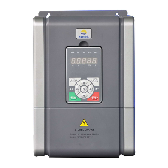
Fan cover Mounting hole Middle enclosure Keypad Bottom enclosure Upper cover Certification Lower cover Nameplate Connection holes of control terminal Size F5 - F7 Size F2 - F4 Connection holes of power terminal - 8 - HD31 Series User Manual V1.6... -
Page 20: Chapter 3 Mechanical Installation
HD31 shall be 2% for each degree centigrade. Max. allowed temperature is 50 ℃ 2. Keep ambient temperature between -10 - +40 . It can improve the running performance if install at location with good ventilation or cooling devices. HD31 Series User Manual V1.6 - 9 -... -
Page 21: Installation Direction And Space Requirements
Just as shown in Table 3-2. Table 3-2 Installation of several inverters HD31 Power 5.5 - 75kW 90 - 132kW ≥50mm ≥100mm ≥50mm ≥100mm ≥50mm ≥100mm ≥50mm ≥100mm ≥50mm ≥100mm ≥50mm ≥100mm - 10 - HD31 Series User Manual V1.6... -
Page 22: Dimensions And Weight
The dimensions and weight of HD31 are as shown in Table 3-3. For the corresponding model of the mounting size, refer to section 2.3 Rated Value, on page 6. 4-Ød Size F2 - F4 4-Ød Size F5 - F6 4-Ød Size F7 HD31 Series User Manual V1.6 - 11 -... -
Page 23: Install And Dismantle Keypad
Figure 3-1 Install keypad There are two steps in Figure 3-2. First, press the hook of the keypad according to direction 1. Second, take out the keypad in direction 2. Figure 3-2 Dismantle keypad - 12 - HD31 Series User Manual V1.6... -
Page 24: Dismantle Plastic Cover
(a). 2. Dismantle the screws of upper cover, as (b). 3. Extrude the hooks at both sides together, take off the upper cover, as (c). Figure 3-3 Remove the plastic cover HD31 Series User Manual V1.6 - 13 -... -
Page 26: Chapter 4 Electrical Installation
Sectional Area S of Phase Conductor (Power Cable) While S ≤ 2.5 2.5 < S ≤ 16 16 < S ≤ 35 S > 35 Installing (mm Min. Sectional Area Sp of Relative Protective Conductor (Ground Cable) (mm HD31 Series User Manual V1.6 - 15 -... -
Page 27: Power Terminal Lug
2.5 - 3.0 4.0 - 5.0 15.5 9.0 - 10.0 17.6 - 22.5 4.3 Main Circuit Terminals and Wiring Danger • The bare portions of the power cables must be bound with insulation tapes. - 16 - HD31 Series User Manual V1.6... -
Page 28: Supply And Motor Terminal
• (+), (-): DC supply input terminals; DC input Frame 7 terminals of power regenerative unit • (+), BR: Braking resistor connection terminals POWER • PE: Ground terminal, connect to the ground MOTOR HD31 Series User Manual V1.6 - 17 -... -
Page 29: Supply And Motor Connection
Mains supply Size F7 connection L1 L2 Braking resistor EMI filter Supply Supply (+) (-) AC reactor ground ground reactor Braking unit MCCB Contactor Mains supply Figure 4-1 Supply and motor connection - 18 - HD31 Series User Manual V1.6... -
Page 30: Control Board And I/O Board
• It is strictly forbidden to connect control terminals other than relay terminals to AC 220V voltage. HD31 includes control board and I/O board, as shown in Figure 4-2. I/O Board Control Board Figure 4-2 Control board and I/O board HD31 Series User Manual V1.6 - 19 -... -
Page 31: Control Board Terminal
Programmable output, contact rating: 250VAC/3A or 30VDC/1A R1A/R1B/R1C Relay output • R1B, R1C: Normally closed. R1A, R1C: Normally open Note: Limit the current within 3A if the relay terminal is to connect to AC 220V voltage signal. - 20 - HD31 Series User Manual V1.6... -
Page 32: I/O Board Terminal
Limit the current within 3A if the relay terminal is to connect to AC 220V voltage signal. 4.4.3 Modbus Communication Terminal Do not use communication terminal and RJ45 Terminal Description simultaneously. 485+ 485- Difinition Control Board Terminal 1, 3 485+ RJ45 4, 5, 6 RJ45 485- Reserved HD31 Series User Manual V1.6 - 21 -... -
Page 33: Jumper
• Pin 2&3 are short-connected, AI3 inputs current signal. AI4 can select voltage or current signal. I/O board • Pin 1&2 are short-connected, AI4 inputs voltage signal (factory setting). • Pin 2&3 are short-connected, AI4 inputs current signal. - 22 - HD31 Series User Manual V1.6... -
Page 34: Chapter 5 Keypad
Increase value or parameter Decrease value or parameter a. Select display parameter and shift bit b. Stop in loop/display the parameter during running STOP a. Enter lower menu b. Confirm to save the data HD31 Series User Manual V1.6 - 23 -... - Page 35 The keypad of HD31 has five LED displays and their meanings are shown in Table 5-3. Table 5-3 LED display description LED Display Meaning LED Display Meaning LED Display Meaning LED Display Meaning Point Full display No display Flash modifiable - 24 - HD31 Series User Manual V1.6...
-
Page 36: Chapter 6 Function Introduction
P02: Water Supply PID Parameter, on page 82 P03: Water Supply AIO Function Parameter, on page 84 P04: Water Supply Fault Protection Parameter, on page 86 P05: Water Supply Time, on page 87 HD31 Series User Manual V1.6 - 25 -... -
Page 37: Group D: Display Parameters
Master setting frequency (Hz) [Actual value] d00.13 Auxiliary setting frequency (Hz) [Actual value] d00.14 Setting frequency [Actual value] d00.15 Setting frequency (after Acc./Dec.) [Actual value] d00.16 Output frequency [Actual value] d00.17 Setting speed [Actual value] - 26 - HD31 Series User Manual V1.6... - Page 38 When selects current output, 0.00V corresponds to 0mA and 10.00V corresponds to 20mA. d00.37 AO2 output [Actual value] Display AO2 output. When selects current output, 0.00V corresponds to 0mA and 10.00V corresponds to 20mA. HD31 Series User Manual V1.6 - 27 -...
- Page 39 Modbus communication status [Actual value] Display Modbus communication status. 0: Normal. 1: Communication timeout. 4: Incorrect data frame content. d00.53 Actual length (m) [Actual value] d00.54 Total length (km) [Actual value] - 28 - HD31 Series User Manual V1.6...
-
Page 40: D02: Water Supply System Status
Pump 4 status [Actual value] d02.05 Pump 5 status [Actual value] d02.06 Pump 6 status [Actual value] d02.07 Pump 7 status [Actual value] 0: Waiting for run. 1: Running. 2: Fault pump. HD31 Series User Manual V1.6 - 29 -... -
Page 41: Group F: General Parameters
2: DI6 pulse setting. Set by F16.17, and its Max. pulse input frequency corresponds to F00.06 (Max. output frequency of HD31). F00.08 Upper limit of run frequency 0.00 - F00.06 [50.00Hz] F00.07 = 0, the upper limit frequency is set by F00.08. - 30 - HD31 Series User Manual V1.6... - Page 42 20), JOGR1 (DI terminal is set to 21), JOGF2 (DI terminal is set to 22), JOGR2 (DI terminal is set to 23). For more information, please see group F15. 2: SCI communication running access. Start and stop by SCI communication port according to communication protocol. HD31 Series User Manual V1.6 - 31 -...
- Page 43 • 1: Stored. Thousand: Switch the frequency access to the analog selection • 0: Not save. • 1: Save. F00.15 Jog run frequency digital setting 1 0.00 - upper limit frequency [5.00Hz] - 32 - HD31 Series User Manual V1.6...
- Page 44 LED flashes) and stops after the elapsed time F00.24 (sleep delay time). • The above sleep function is only valid when F00.11 = 1 (terminal running command access). HD31 Series User Manual V1.6 - 33 -...
- Page 45 • C: PID setting. • 7: AI1 setting. • d: Multi-speed setting. F00.28 Functions selection of STOP key 0,1 [0] 0: Only valid in control of keypad. 1: Valid in all control mode. - 34 - HD31 Series User Manual V1.6...
-
Page 46: F01: Protection Of Parameters
2: Upload the current function code settings to the keypad EEPROM Present setting parameter 2. function parameter F01.03 = 1 / 2 Note: F01.00, F01.02, F01.03, F20.21 - F20.37 and group y do not upload or download. Inverter HD31 Series User Manual V1.6 - 35 -... -
Page 47: F02: Run/Stop Control Parameters
0.00 - 10.00 [0.00s] When the inverter receives run command, it will wait for the delay time set by F02.01 and then start to run. F02.02 Start DWELL frequency setting 0.00 - upper limit [0.00Hz] - 36 - HD31 Series User Manual V1.6... - Page 48 2. If F00.05 = 1, set the variable frequency pump (P01.00 - P01.06) and its corresponding relay (P03.15 - P03.24). F02.09 Search frequency direction reverse 0,1 [0] 0: Not reversed. 1: Reversed. F02.10 Speed search start threshold 0.0 - 60.0 [15.0%] F02.11 Voltage difference 0 - 200 [30%] HD31 Series User Manual V1.6 - 37 -...
- Page 49 • By F02.04 setting the DC braking current DC braking value at stop. Time F02.18 = 0.00s, there is no DC braking process at stop. F02.17F02.18 • F02.16 - F02.18 is valid only when F02.13 = Run command - 38 - HD31 Series User Manual V1.6...
-
Page 50: F03: Acc. And Dec. Parameters
• T5 is the setting Acc. time, T7 is the actual value. T6 is the setting Dec. time, T8 is the actual value. Frequency Frequency F00.06 F00.06 T1:F03.11 T2:F03.12 T3:F03.13 T4:F03.14 Time Time Acc. time Dec. time Ten: Acc./Dec. time reference frequency adjustment • 0: Max. frequency (F00.06). • 1: Set frequency. HD31 Series User Manual V1.6 - 39 -... - Page 51 Dec. time of jog running 0.1 - 6000.0 [6.0s] F03.15 and F03.16 define the Acc./Dec. time of jog running. F03.17 Dec. time of emergency stop 0.1 - 6000.0 [10.0s] Defines the Dec. time of emergency stop. - 40 - HD31 Series User Manual V1.6...
-
Page 52: F04: Process Pid Control
F04.08 defines the process PID differential amplitude limit value. F04.09 defines the sampling cycle of feedback value and the PID regulator calculates once in each sampling cycle. • When F04.07 = 0, the differential is invalid. HD31 Series User Manual V1.6 - 41 -... - Page 53 • When F04.18 = 1 (PID regulation enable reverse), it is invalid. F04.20 Proportional gain (P2) 0.0 - 500.0 [50.0] F04.21 Integral time (I2) 0.01 - 10.00 [1.00s] F04.22 Derivative time (D2) 0.00 - 10.00 [0.00s] - 42 - HD31 Series User Manual V1.6...
- Page 54 Negative characteristics: In the wake-up state, when the feedback value is less than or equal to × (100% - F04.33), the target frequency is ≤ F04.35 and the counting time is ≥ F04.34. the inverter sleep. HD31 Series User Manual V1.6 - 43 -...
-
Page 55: F05: External Setting Curve Parameters
Min. setting. Positive and negative characteristic of line Setting Setting corresponding value corresponding value F05.04 F05.02 F05.08 F05.06 F05.02 F05.04 P/A(setting) P/A(setting) F05.06 F05.08 F05.01 F05.03 F05.01 F05.03 F05.05 F05.07 F05.05 F05.07 - 44 - HD31 Series User Manual V1.6... - Page 56 When selecting jog operation 2 through terminal, set the jog frequency operation according to F05.21. F05.22 Keypad potentiometer curve selection 0 - 3 [3] 0: Straight line 1. 1: Straight line 2. 2: Polyline. 3: No treatment. HD31 Series User Manual V1.6 - 45 -...
-
Page 57: F08: Asyn. Motor Parameters
(oscillation-suppression coefficient) suitably to mitigate the possible oscillation. 3: Motor stator resistance measurement. • The motor is at rest, and the stator resistance of the motor is automatically measured and the measured parameters are automatically written to F08.07. - 46 - HD31 Series User Manual V1.6... - Page 58 Motor 1 core saturation coefficient 3 0.00 - 1.00 [1.00] F08.15 Motor 1 core saturation coefficient 4 0.00 - 1.00 [1.00] F08.16 Motor 1 core saturation coefficient 5 0.00 - 1.00 [1.00] HD31 Series User Manual V1.6 - 47 -...
-
Page 59: F09: V/F Control Parameters
(F08.03) and rated Voltage of manual rotary speed (F08.04) of the motor correctly torque boost according to its nameplate. Frequency F09.08 is relative to percentage of rated frequency (F08.03). F09.08max F08.03 - 48 - HD31 Series User Manual V1.6... - Page 60 F09.19 Motor 1 energy start frequency 0.00 - 50.00 [25.00Hz] F09.20 Motor 1 energy switching point 0.0 - 100.0 [100.0%] F09.21 Motor 1 energy saving detecting times 0 - 5000 [10 times] HD31 Series User Manual V1.6 - 49 -...
-
Page 61: F13: Asyn. Motor 2 Parameters
Motor 2 core saturation coefficient 1 0.00 - 1.00 [1.00] F13.14 Motor 2 core saturation coefficient 2 0.00 - 1.00 [1.00] F13.15 Motor 2 core saturation coefficient 3 0.00 - 1.00 [1.00] - 50 - HD31 Series User Manual V1.6... - Page 62 Motor 2 energy saving detecting times 0 - 5000 [10 times] F13.61 Motor 2 energy voltage recovery time 40 - 4000 [100ms] F13.62 Motor 2 energy voltage decreasing time 40 - 4000 [100ms] HD31 Series User Manual V1.6 - 51 -...
-
Page 63: F15: Digital I/O Terminal Parameters
29: Acc./Dec. is prohibited. 30: Switch to ordinary running mode. 31: Reset the stop status of PLC operation. 32: Pause the process PID. 33: Prohibit the process PID. 34: Hold PID integral. - 52 - HD31 Series User Manual V1.6... - Page 64 0: 2ms. 1: 4ms. 2: 8ms. F15.14 Terminal detecting filter number 0 - 10000 [2] The digital input terminal signal should be delayed and confirmed so as to avoid digital input error. HD31 Series User Manual V1.6 - 53 -...
- Page 65 When there is fault of external equipment, it can select protection. 0: Coast to stop. 1: Emergency stop. 2: Dec. to stop. 3: Continue to run. F15.18 DO1 function 0 - 35 [2] F15.19 DO2 function 0 - 38 [0] - 54 - HD31 Series User Manual V1.6...
- Page 66 • The indicating signal can output when HD31 detects the external fault signal via terminal. 33: Inverter auto-reset fault. 35: Sleep indicating function. 38: High-frequency output (DO2). DO2 can be selected as high-frequency output. HD31 Series User Manual V1.6 - 55 -...
- Page 67 Running frequency F15.28 F15.28 and F15.29 are used to set the zero- F15.29 frequency output control function, refer to the Time right figure. Running status Zero-frequency running output Time Zero-frequency output Time - 56 - HD31 Series User Manual V1.6...
- Page 68 • DO2 will output an indicating signal when DI1 inputs the third pulse until the preset count value reachs seven. • DO1 will output an indicating signal when DI1 inputs the seventh pulse; Output signal of DO1 returns to low level when DI1 inputs the eighth pulse. HD31 Series User Manual V1.6 - 57 -...
-
Page 69: F16: Analog I/O Terminal Parameters
17: Motor 2 reverse rotation electrical torque limit. 5: Process PID feedback. 18: Motor 2 forward regeneration torque limit. 6: Process PID regulating upper limit. 19: Motor 2 reverse regeneration torque limit. - 58 - HD31 Series User Manual V1.6... - Page 70 17: AI4 input (-10 - +10V/0 - 20mA). 18: Output frequency (-1 - +1 times Max. output frequency). 19: Reference frequency (-1 - +1 times Max. output frequency). 20: Set frequency (0 - Max. output frequency). HD31 Series User Manual V1.6 - 59 -...
-
Page 71: F17: Sci Communication Parameters
0.0 - 600.0 [0.0s] Time at communication error > setting time of F17.05, it will be considered as E0029 fault (SCI error). • When F17.05 = 0, it will not detect the communication error. - 60 - HD31 Series User Manual V1.6... -
Page 72: F18: Display Control Parameters
Set the display parameter 1 at stop 0 - 49 [7] F18.09 Set the display parameter 2 at stop 0 - 49 [18] F18.10 Set the display parameter 3 at stop 0 - 49 [20] HD31 Series User Manual V1.6 - 61 -... - Page 73 Line speed display accuracy 0 - 3 [0] 0: Integer. 1: One decimal. 2: Two decimal. 3: Three decimal. Note: The Max. linear velocity must be newly set when the display accuracy is changed. - 62 - HD31 Series User Manual V1.6...
-
Page 74: F19: Function-Boost Parameters
3: Digital setting 3 (the initial value = 0, set by SCI direct communication). 4: AI analog setting. 5: Terminal pulse setting. 6: Process PID output. 7 - 10: AI1 - AI4. 11: Keypad potentiometer. HD31 Series User Manual V1.6 - 63 -... - Page 75 1: To adjust as per the Max. output frequency. • Setting frequency = synthetic frequency + F00.06 × (F19.06 - 100%). 2: To adjust as per the current frequency. • Setting frequency = synthetic frequency × F19.06. - 64 - HD31 Series User Manual V1.6...
- Page 76 Fstart = Start DWELL frequency (F02.02) F02.03 (keeping time of start frequency) Fcmd=Flow Fcmd>Flow Handle by Keep stop Fcmd>Fmin F19.11= 1 F19.11 setting Fcmd=F19.11 Confirmed frequency Fcmd>Fstart H=Fstart Reach F2.03 or H=Fcmd HD31 Series User Manual V1.6 - 65 -...
- Page 77 F19.15 Reference voltage of trip-free operation 220V inverter 210 - 370 [248V] at the moment of power-off 380V inverter 400 - 670 [430V] 660V inverter 620 - 1130 [747V] - 66 - HD31 Series User Manual V1.6...
- Page 78 210 - 370 [390V] 380V inverter 650 - 790 [690V] 660V inverter 900 - 1180 [1150V] If the stall overvoltage point is set a little lower, Dec. time should be comparatively longer. HD31 Series User Manual V1.6 - 67 -...
- Page 79 • The flux brake effect can be adjusted by F19.40, F19.41. • Valid only when V/f control is active. Note: Do not use this function during frequent braking, which may damage the motor. - 68 - HD31 Series User Manual V1.6...
- Page 80 Auxiliary frequency selected as PID, PID takes as PID adjustment up limit F19.35 × main given frequency. F19.36 Auxiliary PID output limit increase 0.0 - 100.0 [0.0%] Auxiliray PID output limit = output limit comfirmed by F19.35 + F19.36 × F00.06. HD31 Series User Manual V1.6 - 69 -...
- Page 81 Brake Function (F19.24 - F19.25, F19.40 - F19.41) Ref. Code Function Description Setting Range [Default] F19.40 Flux brake PI regulator Kp 0 - 4000 [1000] F19.41 Flux brake PI regulator Ki 0 - 500 [20] - 70 - HD31 Series User Manual V1.6...
-
Page 82: F20: Fault Protection Parameters
If the output current of HD31 < F20.04 and exceeds the time defined by load-loss detection time (F20.05), HD31 will alarm E0018 fault (inverter output load-loss). • F20.04 or F20.05 = 0, HD31 will not detect load-loss fault. HD31 Series User Manual V1.6 - 71 -... - Page 83 If the PID feedback value < F20.14 in the detection time (F20.15), HD31 will alarm E0026 fault (PID feedback loss). • F20.14 or F20.15 = 0, HD31 will not detect PID feedback loss fault. - 72 - HD31 Series User Manual V1.6...
- Page 84 • 1: Faulty relay acts. Ten: In the undervoltage process • 0: Faulty relay doesn’t act. • 1: Faulty relay acts. Note: Relay needs to be set as No. 31 function (inverter fault). HD31 Series User Manual V1.6 - 73 -...
- Page 85 F20.22 - F20.29 record the inverter status parameters at the last fault. F20.30 - F20.37 record the type and interval per time of four faults before the latest. The interval’s unit is 0.1 hour. - 74 - HD31 Series User Manual V1.6...
-
Page 86: F23: Pwm Control Parameters
• 2.2kW and below models (380V and 220V) factory value 15.00Hz. • Other models, factory value 10.00Hz. Note: F23.04 setting value is F23.05 - 2.00Hz, F23.05 lower limit is F23.04 + 2.00Hz. HD31 Series User Manual V1.6 - 75 -... -
Page 87: Group P: Special Parameter For Multi-Pump Water Supply
Pressure tolerance for adding pump 0.0 - 50.0 [10.0%] P00.07 Detected time for adding pump 0.0 - 3600.0 [5.0s] P00.08 Upper switch frequency when adding variable frequency pump P02.27 - upper limit [50.00Hz] - 76 - HD31 Series User Manual V1.6... - Page 88 • At the same time, the pump accelerates to upper limit frequency according to P00.12, then performs PI adjustment. Note: Reduce the power frequency pump preferentially when there are inverter&power frequency pumps which run with power frequency. P00.13 Breaking delay of pump 1 contactor 0.000 - 5.000 [0.020s] HD31 Series User Manual V1.6 - 77 -...
- Page 89 P00.19, the sleep is awakened. If P00.17 = 1 , the sleep pump is disconnected. When sleep is awakened, HD31 drive pump is preferably added if there is any waited in the system. If there is power frequency pump waiting, it is added directly. - 78 - HD31 Series User Manual V1.6...
- Page 90 • Before switch cariable frequency into power frequency, detect phase sequency. And difference of power frequency phase angle will be changed within range of P00.32 - P00.38. Note: Detailed steps refer to 7.2 Debug for Switching between VF and PF, on page 92. HD31 Series User Manual V1.6 - 79 -...
-
Page 91: P01: Water Supply Pump Parameter
P01.02 Pump 3 type 0 - 4 [0] P01.03 Pump 4 type 0 - 4 [0] P01.04 Pump 5 type 0 - 4 [0] P01.05 Pump 6 type 0 - 4 [0] - 80 - HD31 Series User Manual V1.6... - Page 92 5.5kW and below motor 0.01 - 99.99A [Depend on HD31] Please set the above rated current according to the nameplate on the motor. These parameters will affect the overload protection of HD31 for the motor. HD31 Series User Manual V1.6 - 81 -...
-
Page 93: P02: Water Supply Pid Parameter
0.0 - P05.03 × 10 [0.0kg/cm P02.20 T9 time pressure 0.0 - P05.03 × 10 [0.0kg/cm P02.22 T10 time pressure 0.0 - P05.03 × 10 [0.0kg/cm P02.24 T11 time pressure 0.0 - P05.03 × 10 [0.0kg/cm - 82 - HD31 Series User Manual V1.6... - Page 94 1: Save. When P02.00 = 0 and inverter is in stop/running, setted pressure is displaying. We can adjust the setted pressure through key. After power-off, adjusted pressure value can be saved by P02.35. HD31 Series User Manual V1.6 - 83 -...
-
Page 95: P03: Water Supply Aio Function Parameter
• The sewage pump is triggered into use when WL of sewage pool exceeds upper limit WL; Otherwise it deactivates and stops output. Note: After setting the P03.04 - P03.09 functions, the corresponding F15.00 - F15.05 function are invalid. - 84 - HD31 Series User Manual V1.6... - Page 96 23: The supply system is in running status. • This signal is valid when the water supply system is in running status. Note: After setting the P03.13 - P03.15 functions, the corresponding functions of F15.18 - F15.20 are invalid. HD31 Series User Manual V1.6 - 85 -...
-
Page 97: P04: Water Supply Fault Protection Parameter
• If the the system had set auto-reset function, it will reset for the corresponding times and carry out the above operation. Otherwise it will carry out the above operation directly without reset. - 86 - HD31 Series User Manual V1.6... -
Page 98: P05: Water Supply Time Parameter
2. When P05.04 = 2, set the F05.00 ten to 1 and set F05.05 = 20.0%. When P05.04 = 0 or 1, set F05.00 ten to 0 and set F05. 05 = 0.0%. HD31 Series User Manual V1.6 - 87 -... - Page 99 1. Fault display (unit): Display EP0 + fault pump record (P04.04), if pump No.1 is faulty, display EP001 (EP0 + 01), 2. Fault pump clear (ten): After the system stops and the keypad displays the status interface, press the STOP key to clear. - 88 - HD31 Series User Manual V1.6...
-
Page 100: Chapter 7 Application Reference
WL signal. • Backup pressure function: 0.2Mpa backup pressure. 3. Pressure gauge selection: Remote control, DC 0 - 10V output, 1Mpa range. HD31 system wiring is shown in figure below. HD31 Series User Manual V1.6 - 89 -... - Page 101 Chapter 7 Application Reference Shenzhen Hpmont Technology Co., Ltd. One-to-six wiring - 90 - HD31 Series User Manual V1.6...
- Page 102 Pressure setting of analog water supply P03.00 AI1 function: Analog pressure setting P03.01 AI2 function: Analog feedback setting P02.34 Regulating characteristic of close-loop: Positive P02.28 - P02.33 Parameters relative to PID, depend on actual condition HD31 Series User Manual V1.6 - 91 -...
-
Page 103: Debug For Switching Between Vf And Pf
• Switching frequency should be greater than the power frequency of the grid 0.50 - 1.00Hz. When P00.00 = 1 (water supply debug mode), change the frequency of F00.13. When P00.00 = 0 (water supply operation mode), change the value of P00.08. - 92 - HD31 Series User Manual V1.6... -
Page 104: Chapter 8 Troubleshooting
Chapter 8 Troubleshooting Chapter 8 Troubleshooting HD31 series inverter has inbuilt protective and warning self-diagnostic functions. If a fault occurs, the fault code will be displayed on the keypad. At the same time, faulty relay acts, accordingly HD31 stops output and the motor coasts to stop. - Page 105 • Check load and mechanical • Load disappears or falls suddenly Inverter output load- transmission devices E0018 loss • Parameters are not set properly • Set the parmeters properly (F20.03 - F20.05) - 94 - HD31 Series User Manual V1.6...
- Page 106 • F00.05 = 1 and P00 .3 = 1, input • Replace the inverter power input E0037 Input wrong phase phase of inverter is negative phase phase sequence (d00.19 = 1) Note: E0022 does not affect normal running of HD31. HD31 Series User Manual V1.6 - 95 -...
-
Page 108: Chapter 9 Accessories
Model Model (mH-A) (mH-A) (mH-A) HD-AOL- HD-DCL- HD31-4T045P HD-AIL-4T037 0.19-75 0.08-80 0.35-100 4T037 4T037 HD-AOL- HD-DCL- HD31-4T055P HD-AIL-4T045 0.16-90 0.06-100 0.29-120 4T045 4T045 HD-AOL- HD-DCL- HD31-4T075P HD-AIL-4T055 0.13-115 0.04-125 0.23-150 4T055 4T055 HD31 Series User Manual V1.6 - 97 -... -
Page 109: Braking Resistor And Braking Unit
Bigger resistor can protect the braking system in faulty condition, but oversized resistor may bring a capacity decrease, leading to over voltage protection. 2. The braking resistor should be mounted in a ventilated metal housing to prevent inadvertent contact during it works, for the temperature is high. - 98 - HD31 Series User Manual V1.6... - Page 110 Bit1&Bit0: Acc./Dec./constant Bit3: DC braking (including start d00.10 Inverter status and stop DC braking) Hundred: Bit0: Parameter auto-tuning Bit2: Speed limiting value Bit3: Control mode Thousand: Bit0: Stall overvoltage Bit1: Current limiting HD31 Series User Manual V1.6 - 99 -...
- Page 111 -10.00 - +10.00V AI4 input voltage (after d00.34 -10.00 - +10.00V disposal) DI6 terminal pulse input d00.35 0 - 50000Hz frequency d00.36 AO1 output 0.00 - 10.00V d00.37 AO2 output 0.00 - 10.00V - 100 - HD31 Series User Manual V1.6...
- Page 112 0.0 - 999.9kW.h consumption d00.59 High energy con. for this run 0 - 65535k kW.h d00.60 Low energy con. for this run 0.0 - 999.9kW.h 1 - 100 d00.61 Present fault 100: Undervoltage HD31 Series User Manual V1.6 - 101 -...
- Page 113 4: Terminal pulse setting 6 - 9: AI1 - AI4 setting 10: Keypad potentiometer setting 0: Keypad running access Command setting access 1: Terminal running access F00.11 × selection 2: SCI communication running access - 102 - HD31 Series User Manual V1.6...
- Page 114 1: Enable F00.22 Sleep wake up time 0.0 - 360.0s 1.0s 0.1s ○ F00.24 Sleep delay time 0.0 - 6000.0s 1.0s 0.1s ○ F00.25 Sleep frequency 0.00Hz - upper limit 0.00Hz 0.01Hz ○ HD31 Series User Manual V1.6 - 103 -...
- Page 115 Multi-speed setting 0: Only valid in control of Functions selection of STOP keypad F00.28 ○ 1: Valid in all control mode F01: Protection of Parameters F01.00 User’s password 00000 - 65535 ○ - 104 - HD31 Series User Manual V1.6...
- Page 116 0.00 - 10.00s 0.00s 0.01s × DWELL frequency F02.04 DC braking current setting 0 - 100% (HD31 rated current) × F02.05 DC braking time at start 0.00 - 60.00s 0.50s 0.01s × HD31 Series User Manual V1.6 - 105 -...
- Page 117 Unit: Mode selection of Acc. and Dec. 0: Linear Acc. or Dec. 1: S-curve Acc. or Dec. F03.00 Acc./Dec. mode selection ○ Ten: Acc./Dec. time reference frequency adjustment 0: Max. frequency (F00.06) 1: Set frequency - 106 - HD31 Series User Manual V1.6...
- Page 118 0.00% 0.01% ○ F04.04 Proportional gain (P1) 0.0 - 500.0 50.0 ○ F04.05 Integral time (I1) 0.01 - 10.00s 1.00s 0.01s ○ F04.06 Integral upper limit 0.0 - 100.0% 100.0% 0.1% ○ HD31 Series User Manual V1.6 - 107 -...
- Page 119 PID parameter switching F04.25 F04.24 - 100.0% 100.0% 0.1% ○ point 2 F04.27 Pulse of each turn 1 - 9999 1024 × F04.28 Max. closed loop speed 1 - 24000rpm 1500rpm 1rpm × - 108 - HD31 Series User Manual V1.6...
- Page 120 0.0 - 100.0% 100.0% 0.1% ○ value of polyline Inflection point 2 reference of F05.11 F05.13 - F05.09 100.0% 0.1% ○ polyline Inflection point 2 F05.12 0.0 - 100.0% 100.0% 0.1% ○ corresponding value HD31 Series User Manual V1.6 - 109 -...
- Page 121 90kW above: 0.000 - 50.000 mH 0.001 mH 7.5kW or below: 0.0 - 5000.0mH 0.1mH Mutual inductance of motor F08.10 11 - 90kW: 0.00 - 500.00mH 0.01mH × 90kW above: 0.000 - 50.000 mH 0.001 mH - 110 - HD31 Series User Manual V1.6...
- Page 122 Compensation time constant F09.12 0.1 - 25.0s 2.0s 0.1s × of motor 1 0: Disabled F09.14 AVR function of motor 1 1: Enabled all the time ○ 2: Disabled in Dec. process HD31 Series User Manual V1.6 - 111 -...
- Page 123 11 - 75kW: 0.00 - 500.00mH 0.01mH × 90kW above: 0.000 - 50.000 mH 0.001 mH 7.5kW or below: 0.00 - 99.99A 0.01A Idling exciting current of F13.12 × motor 2 7.5kW above: 0.0 - 999.9A 0.1A - 112 - HD31 Series User Manual V1.6...
- Page 124 0.0 - 100.0% 5.0% 0.1% ○ Motor 2 core saturation F13.53 0.00 - 1.00 1.00 0.01 × coefficient 4 Motor 2 core saturation F13.54 0.00 - 1.00 1.00 0.01 × coefficient 5 HD31 Series User Manual V1.6 - 113 -...
- Page 125 26: Acc./Dec. time selects terminal 1 27: Acc./Dec. time selects terminal 2 28: Acc./Dec. mode selection F15.03 DI4 function 29: Acc./Dec. prohibited × 30: Switch to ordinary running mode 31: Reset the stop status of PLC operation - 114 - HD31 Series User Manual V1.6...
- Page 126 Acc./Dec. rate of UP/DN F15.12 0.00 - 99.99Hz/s 1.00Hz/s 0.01Hz/s × terminal 0: 2ms Terminal detecting F15.13 1: 4ms ○ interval 2: 8ms Terminal detecting filter F15.14 0 - 10000 ○ number HD31 Series User Manual V1.6 - 115 -...
- Page 127 20: Output data from SCI communication 21: Preset operating time out F15.21 RLY2 function ○ 22: Timing function output 23: Preset counting value reach 24: Indicate counting value reach 25: Set length arrive - 116 - HD31 Series User Manual V1.6...
- Page 128 0 - 65535h F15.36 Preset running time ○ 0: Preset operating time is disabled Preset counting value F15.37 F15.38 - 9999 ○ arriving Specified counting value F15.38 0 - F15.37 ○ arriving HD31 Series User Manual V1.6 - 117 -...
- Page 129 7: Process PID regulating lower limit 8: Motor overheating signal input 9: Motor 1 forward rotation torque limit F16.02 AI2 function × 10: Motor 1 reverse electric torque limit 11: Motor 1 forward regeneration rotation torque limit - 118 - HD31 Series User Manual V1.6...
- Page 130 ○ F16.16 AI4 filter time 0.01 - 10.00s 0.05s 0.01s ○ Max. input pulse F16.17 0.0 - 50.0kHz 10.0kHz 0.1kHz ○ frequency F16.18 Input pulse filter time 0 - 500ms 10ms ○ HD31 Series User Manual V1.6 - 119 -...
- Page 131 F17: SCI Communication Parameters 0: 1-8-2 format, no parity, RTU 1: 1-8-1 format, even parity, RTU F17.00 Data format × 2: 1-8-1 format, odd parity, RTU 6: 1-8-11 format, no parity, RTU - 120 - HD31 Series User Manual V1.6...
- Page 132 × 0.0: Not detected communication overtime timeout F18: Display Control Parameters 0: Chinese F18.00 Language selection ○ 1: English Display contrast of the F18.01 1 - 10 ○ LCD keypad HD31 Series User Manual V1.6 - 121 -...
- Page 133 38: Process PID feedback 39: Process PID error 40: Process PID integral value 41: Process PID output Set the display F18.12 ○ parameter 5 at stop 42: External couting value 43: Input terminal status - 122 - HD31 Series User Manual V1.6...
- Page 134 4: Auxiliary and main auxiliary operation switch Analog auxiliary setting F19.02 0.00 - 9.99 1.00 0.01 ○ coefficient Initial value of digital F19.03 0.00Hz - F00.06 0.00Hz 0.01Hz ○ auxiliary frequency HD31 Series User Manual V1.6 - 123 -...
- Page 135 × moment of power-off 660V inverter: 620 - 1130V 747V 0: Prohibited F19.16 Restart after power-off × 1: Enabled Delay time for restart F19.17 0.00 - 10.00s 2.00s 0.01s ○ after power-off - 124 - HD31 Series User Manual V1.6...
- Page 136 Record of length disposal F19.34 ○ at stop 1: No change F19.35 Auxiliary PID output limit 0.0 - 100.0% 100.0% 0.1% × Auxiliary PID output limit F19.36 0.0 - 100.0% 0.0% 0.1% × increase HD31 Series User Manual V1.6 - 125 -...
- Page 137 × 1: 260 - 460V 2: 200 - 460V Ten, hundred: Reserved Flux brake PI regulator F19.40 0 - 4000 1000 ○ F19.41 Flux brake PI regulator Ki 0 - 500 ○ - 126 - HD31 Series User Manual V1.6...
- Page 138 3: It detects all the time in running process, and then cut off the output after detecting (fault) 4: It detects only at the same speed, and then cut off the output after detecting (fault) HD31 Series User Manual V1.6 - 127 -...
- Page 139 Auto reset interval 0.01 - 200.00s/time 0.01s/time ○ Unit: In auto reset process Ten: In the undervoltage process Faulty relay action F20.20 ○ selection 0: Faulty relay doesn’t act 1: Faulty relay acts - 128 - HD31 Series User Manual V1.6...
- Page 140 7.5kW above: Actual value 0.0A 0.1A Output current at the last F20.26 fault 7.5kW or below: Actual value 0.00A 0.01A Input terminal status at F20.27 0 - 0x1FF the last fault HD31 Series User Manual V1.6 - 129 -...
- Page 141 × input 2: AI terminal input Upper limit WL of intake P00.02 0.0 - 100.0% 50.0% 0.1% ○ pool Lower limit WL of intake P00.03 0.0% - P00.02 30.0% 0.1% ○ pool - 130 - HD31 Series User Manual V1.6...
- Page 142 0.0 - 100.0% 0.0% 0.1% ○ coefficient Interval of shutdown the P00.21 0.0 - 60.0s 10.0s 0.1s ○ pump and water supply Detected time of P00.22 0.0 - 3600.0s 6.0s 0.1s ○ shutdown detection HD31 Series User Manual V1.6 - 131 -...
- Page 143 7 Dealy of pump 2 P00.39 contactor breaking Dealy of pump 2 P00.40 0.000 - 5.000s 0.020s 0.001s ○ contactor touching Dealy of pump 3 P00.41 contactor breaking - 132 - HD31 Series User Manual V1.6...
- Page 144 Rated current of pump 6 × 5.5kW and below motor: 0.01 - 99.99A 0.01A 5.5kW above motor: 0.1 - 999.9A 0.1A P01.13 Rated current of pump 7 × 5.5kW and below motor: 0.01 - 99.99A 0.01A HD31 Series User Manual V1.6 - 133 -...
- Page 145 P02.31 Sampling time (T) 0.01 - 30.00s 0.50s 0.01s ○ P02.32 Bias limit 0.0 - 20.0% 2.0% 0.1% ○ Output wave filter of P02.33 0.01 - 30.00 0.50s 0.01s ○ pressure closed-loop - 134 - HD31 Series User Manual V1.6...
- Page 146 0.1s ○ pressure protection Setting value of under- P04.02 0.00 - P05.03 × 10kg/cm 0.00kg/cm ○ 0.10kg/cm pressure protection Detected time of under- P04.03 0.0 - 3600.0s 300.0s 0.1s ○ pressure protection HD31 Series User Manual V1.6 - 135 -...
- Page 147 Unit: Water supply failure status display Display EP0 + fault pump record (P04.04) Water supply fault status P05.06 0x00 ○ display and clearing Ten: STOP key to clear faulty pump status 0: Prohibited 1: Enable - 136 - HD31 Series User Manual V1.6...
- Page 148 Appendix B Modbus Communication Protocol Appendix B Modbus Communication Protocol 1. Introduction HD31 series inverters provide one RS485 communication interface which uses the standard Modbus communication protocol. By using the host computer (including communication devices such as computer and PLC) the user can operate to read-write the inverter’s function code, read the status parameters and write the control...
- Page 149 To rewrite single function parameter or control parameter 0x41 Don't save when power-off 0x10 Whether to save when power-off is set by F17.09 To rewrite numbers of function parameters or control parameters 0x43 Save when power-off - 138 - HD31 Series User Manual V1.6...
- Page 150 0x0000 - 0xFFFF 0x0000 - 0xFFFF Response Address Code Register Address Register Content CRC/LRC Check Frame Data frame bytes Value or range 1 - 247 0x06, 0x41 0x0000 - 0xFFFF 0x0000 - 0xFFFF HD31 Series User Manual V1.6 - 139 -...
- Page 151 Incorrect information frame, including incorrect information length and incorrect checking. 0x20 Parameters cannot be modified. 0x21 Parameters are unchangeable when the controller is in running status. 0x22 Parameters are protected by password. - 140 - HD31 Series User Manual V1.6...
- Page 152 Retained or Not at Power Loss 0x3200 Control command character Saving or not is set by hundreds bit 0x3201 Running frequency setting of F00.14 in power failure 0x3202 Auxiliary running frequency setting 0x3204 Virtual terminal control setting HD31 Series User Manual V1.6 - 141 -...
- Page 153 1: RLY2 output is valid Bit4 0: RLY3 output is invalid 1: RLY3 output is valid Bit5 0: RLY4 output is invalid 1: RLY4 output is valid Bit6 - Bit15 Reserved Reserved - 142 - HD31 Series User Manual V1.6...
- Page 154 0x331F AI3 voltage 0x334B Pump 4 status 0x3320 AI3 voltage (after calculating) 0x334C Pump 5 status 0x3321 AI4 voltage 0x334D Pump 6 status 0x3322 AI4 voltage (after calculating) 0x334E Pump 7 status HD31 Series User Manual V1.6 - 143 -...
- Page 155 Modbus. 6. CRC Checking Code of online calculating CRC is shown below: unsigned int crc_check(unsigned char *data,unsigned char length) int i; unsigned crc_result=0xffff; while(length--) crc_result^=*data++; for(i=0;i<8;i++) if(crc_result&0x01) crc_result=(crc_result>>1)^0xa001; else crc_result=crc_result>>1; return (crc_result=((crc_result&0xff)<<8)|(crc_result>>8)); - 144 - HD31 Series User Manual V1.6...
- Page 156 Code Register Address Register Content Checksum Frame 0x02 0x06 0x32 0x00 0x10 0x04 0x8B 0x42 Response Address Code Register Address Register Content Checksum Frame 0x02 0x06 0x32 0x00 0x10 0x04 0x8B 0x42 HD31 Series User Manual V1.6 - 145 -...
- Page 157 Code Register Address Register Content Checksum Frame 0x02 0x06 0x32 0x00 0x11 0x00 0x8B 0x11 Response Address Code Register Address Register Content Checksum Frame 0x02 0x06 0x32 0x00 0x11 0x00 0x8B 0x11 - 146 - HD31 Series User Manual V1.6...
- Page 158 Hpmont Group Company Shenzhen Hpmont Techmology Co., Ltd. Add: Building 28, Wangjingkeng Industry Park, Xili Dakan, Nanshan District, Shenzhen, China, 518055 Tel: 86 755 2679 1688 Fax: 86 755 2699 4395 Email: marketing@hpmont.com HPMONT (Hong Kong) Co., Ltd. Add: Room 709, 7/F, Silvercord Tower 1, 30 Canton Road, Tsim Sha Tsui, -Kowloon. Hong Kong...
Need help?
Do you have a question about the HD31 Series and is the answer not in the manual?
Questions and answers