Table of Contents
Advertisement
Quick Links
Advertisement
Table of Contents

Related Manuals for hpmont HD30-2D0P4G 1.0 5.8 2.5 0.4 HD30-2D0P7G 1.5 10.5 4.0 0.75 HD30-2D1P5G 2.8 18.5 7.5 1.5 HD30-2D2P2G HD30-2T3P7G 5.9 19 17 3.7 HD3


Summary of Contents for hpmont HD30-2D0P4G 1.0 5.8 2.5 0.4 HD30-2D0P7G 1.5 10.5 4.0 0.75 HD30-2D1P5G 2.8 18.5 7.5 1.5 HD30-2D2P2G HD30-2T3P7G 5.9 19 17 3.7 HD3
- Page 2 FOREWORD Thank you for purchasing HD30 series vector control inverter manufactured by Shenzhen Hpmont Technology Co., Ltd. This User Manual describes how to use HD30 series inverters and their installation wiring, parameter setting, troubleshooting and daily maintenance etc. Before using the product, please read through this User Manual carefully. In addition, please do not use this product until you have fully understood safety precautions.
- Page 3 Connection with peripheral devices Three-phase AC power supply MCCB Contactor AC input reactor EMI filter Braking resistor (optional) HD30 series inverter DC reactor (optional) Ground connection EMI filter AC output reactor Motor Ground connection...
- Page 4 QUICK START for USER MENU of GROUP U User menu of Group U After map the parameters which will be used to the Group U, simply operating the Group U can directly achieve parameters of read and write. When the user selects fewer functional parameters which are scattered in the function menu, the user can map the function menu to the user menu.
- Page 5 Factory setting The user menu Group U can set up to 16 parameters, of which there are 14 parameters have been set. Setting value Setting value U00.00 00.01 (control mode selection) U00.14 03.01 (acceleration time 1) 00.06 (inverter maximum U00.02 U00.16 03.02 (deceleration time 1) output frequency)
- Page 6 QUICK START for HD30 OPERATION Note: Some parameters have been set (factory setting) so that you could not set for the initial use. Control the start/stop and set the running frequency via using the display panel 1. Power on. Using the display panel can set motor parameters (see the motor nameplate parameter), running frequency and acceleration/deceleration time.
- Page 7 Control the start/stop via terminals and set the running frequency via display panel 1. The terminal DI1 is forward running signal input, and DI2 is reverse running signal input, their wirings are as following figure. Output indicating signal at running Forward terminal Common terminal Reverse terminal...
- Page 8 Control the start/stop via terminals and set the running frequency via analogue 1. The terminal DI1 is forward running signal input, and DI2 is reverse running signal input, their wirings are as following figure. Forward terminal Output indicating signal at running Reverse terminal Common terminal Fault indication normally closed contact...
- Page 9 Control the start/stop via terminals and set the running frequency via communication 1. The terminal DI1 is forward running signal input, and DI2 is reverse running signal input, their wirings are as following figure. Forward terminal Output indicating signal at running Reverse terminal Common terminal Fault indication normally closed contact...
- Page 10 Control the start/stop and set the running frequency via using communication 1. The communication wirings are as following figure. Output indicating signal at running Common terminal MODBUS Fault indication normally closed contact SCI communication communication terminal Fault indication normally open contact 2.
- Page 11 5. Modify the running frequency via SCI communication function code 0X06 writing register 0x3201. Such as: modify the local address two of slave with running frequency of 45.00Hz, as following table. Address Code Register address Register content Checksum Command 0x02 0x06 0x32 0x01...
-
Page 12: Table Of Contents
CONTENTS Chapter 1 Safety Information and Precautions ................1 1.1 Safety Definition ....................... 1 1.2 About Motor and Load ...................... 1 1.3 Installation Limitation ......................2 Chapter 2 Product Information ...................... 5 2.1 Model Explanation ......................5 2.2 Nameplate ........................5 2.3 Specifications ........................ - Page 13 4.5.6 Conduction, Radiation and Radio Frequency Interference Countermeasures ..38 4.5.7 Input and Output Reactor ................... 38 Chapter 5 Operation Instructions ....................39 5.1 Function Description ....................... 39 5.1.1 Inverter Run Command Source ................39 5.1.2 Inverter Frequency Setting Source ..............39 5.1.3 Inverter Status ....................
- Page 14 6.2.21 Group F20 Protection of Fault Parameters ............. 116 6.2.22 Group F21 Reserved ..................119 6.2.23 Group F22 Reserved ..................119 6.2.24 Group F23 PWM Control Parameters ............. 120 6.3 Group U User Menu Mode Display Parameters ............121 6.4 Group y Manufacturer Function Parameters ..............122 Chapter 7 Troubleshooting ......................
- Page 16 Safety Information and Precautions Product Information Mechanical Installation Electrical Installation Operation Instructions Function Introduction Troubleshooting Maintenance Options Parameters User Menu Setting Table Communication Protocol...
-
Page 18: Chapter 1 Safety Information And Precautions
Shenzhen Hpmont Technology Co., Ltd Chapter 1 Safety Information and Precautions Chapter 1 Safety Information and Precautions 1.1 Safety Definition Danger: A Danger contains information which is critical for avoiding safety hazard. Danger Warning: A Warning contains information which is essential for avoiding a risk of damage to product or other equipments. -
Page 19: Installation Limitation
Chapter 1 Safety Information and Precautions Shenzhen Hpmont Technology Co., Ltd By setting the skip frequency of the inverter (F05.17-F05.19) to avoid the load device or the motor mechanical resonance point. Check the insulation of the motor For the first time using of the motor or after long time storage, it need check the insulation of the motor to avoid damage the inverter because of the worse insulation motor. - Page 20 Shenzhen Hpmont Technology Co., Ltd Chapter 1 Safety Information and Precautions In the altitude exceeded 1000 meters area, since the heatsink efficiency will be reduced because of the tenuous air, the inverter should be derating. Figure 1-1 is the derating curve of the inverter rated current and the altitude.
-
Page 22: Chapter 2 Product Information
Shenzhen Hpmont Technology Co., Ltd Chapter 2 Product Information Chapter 2 Product Information 2.1 Model Explanation HD30 - 4 T 5P5 G / 7P5 P Product types G : general P : fan and pump Adaptive motor power Refer to section ratings... -
Page 23: Specifications
Chapter 2 Product Information Shenzhen Hpmont Technology Co., Ltd 2.3 Specifications Item Specification Single/three-phase: 200-240V, 50/60Hz Rated voltage and frequency Three-phase: 380-460V, 50/60Hz Voltage: fluctuating within ± 10%, imbalance rate < 3% Accuracy Frequency: ± 5% Output voltage 0-input voltage Output frequency 0-400.00Hz... - Page 24 Shenzhen Hpmont Technology Co., Ltd Chapter 2 Product Information Item Specification Stall overvoltage Bus voltage can auto-control against overvoltage fault Auto-limited current Output current can auto-limit against overcurrent fault protection Overload pre-alarm and Overload early pre-alarm and protect alarm Load loss protection...
- Page 25 Chapter 2 Product Information Shenzhen Hpmont Technology Co., Ltd Item Specification Five LEDs display Setting frequency, output frequency, output voltage, output current, LED display motor speed, output torque, switching value terminal, status parameter, programm menu parameter and fault code etc.
-
Page 26: Ratings
Shenzhen Hpmont Technology Co., Ltd Chapter 2 Product Information 2.4 Ratings Rated capacity Rated input Rated output Motor power Model (kVA) current(A) current(A) (kW) Single/three-phase power supply: 200-240V, 50/60Hz HD30-2D0P4G HD30-2D0P7G 10.5 0.75 HD30-2D1P5G 18.5 HD30-2D2P2G 24.1 Three-phase power supply: 200-240V, 50/60Hz... -
Page 27: Parts Of Inverter
Chapter 2 Product Information Shenzhen Hpmont Technology Co., Ltd Rated capacity Rated input Rated output Motor power Model (kVA) current(A) current(A) (kW) HD30-4T200G/220P 250/280 385/430 380/426 200/220 HD30-4T220G/250P 280/309 430/475 426/470 220/250 HD30-4T250G/280P 309/349 475/535 470/530 250/280 HD30-4T280G/315P 349/398 535/609... -
Page 28: Chapter 3 Mechanical Installation
Shenzhen Hpmont Technology Co., Ltd Chapter 3 Mechanical Installation Chapter 3 Mechanical Installation 3.1 Installation Precautions Danger • Do not install if the inverter is imcomplete or impaired. • Make sure that the inverter is far from the explosive and flammability things. -
Page 29: Installation Direction And Space Requirements
Chapter 3 Mechanical Installation Shenzhen Hpmont Technology Co., Ltd 3.3 Installation Direction and Space Requirements To achieve good cooling efficiency, install the inverter perpendicularly and always provide the following space to allow normal heat dissipation. The requirements on mounting space and clearance are shown in Figure 3-1and Table 3-1. -
Page 30: Dimensions And Mounting Size
Shenzhen Hpmont Technology Co., Ltd Chapter 3 Mechanical Installation 3.4 Dimensions and Mounting Size 4-Ød LO/RE LOCK Figure1 4-Ød F W D R E V A L M L O /R E L O C K R P M Figure2 4-Ød... - Page 31 Chapter 3 Mechanical Installation Shenzhen Hpmont Technology Co., Ltd Table 3-2 HD30 dimensions Dimension (mm) Mounting size (mm) Structure Model Figure size (kg) HD30-2D0P4G HD30-2D0P7G HD30-2D1P5G Frame 1 HD30-2D2P2G Figure 1 HD30-4T0P7G HD30-4T1P5G HD30-4T2P2G HD30-2T3P7G Frame 2 HD30-4T3P7G/5P5P Figure 1...
- Page 32 Shenzhen Hpmont Technology Co., Ltd Chapter 3 Mechanical Installation Dimension (mm) Mounting size (mm) Structure Model Figure size (kg) HD30-4T315G/355P Frame 10 HD30-4T355G/400P 1316 1286 1250 Figure 3 HD30-4T400G/450P HD30 series cabinet appearance is shown as Figure 3-3 and the dimension is as Table 3-3.
-
Page 33: Display Panel Installation And Dismantle
Chapter 3 Mechanical Installation Shenzhen Hpmont Technology Co., Ltd 3.5 Display Panel Installation and Dismantle According to the direction of the Figure 3-4, press the display panel until hear a “click” sound. Do not install the display panel from other directions or it will cause poor contact. -
Page 34: Plastic Cover Dismantle
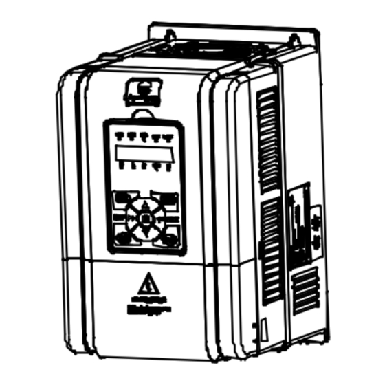
Shenzhen Hpmont Technology Co., Ltd Chapter 3 Mechanical Installation 3.6 Plastic Cover Dismantle The upper cover and the lower cover of the HD30 series inverter are removable. The dismantle step is shown as Figure 3-6. Before removing the upper cover, please take away the display panel. -
Page 36: Chapter 4 Electrical Installation
Shenzhen Hpmont Technology Co., Ltd Chapter 4 Electrical Installation Chapter 4 Electrical Installation 4.1 Wiring Precautions Danger • Only qualified electrical engineer can perform wiring job. • Only when the power supply switch is completely off can you do the wiring job. - Page 37 Chapter 4 Electrical Installation Shenzhen Hpmont Technology Co., Ltd Input Protection Main Circuit (mm Control Model Circuit (mm MCCB (A) Contactor (A) Supply Cables Motor Cables ≥0.5 HD30-2T015G ≥0.5 HD30-2T018G ≥0.5 HD30-2T022G ≥0.5 HD30-2T030G ≥0.5 HD30-2T037G ≥0.5 HD30-2T045G ≥0.5 HD30-2T055G ≥0.5...
-
Page 38: Main Circuit Terminals And Wiring
Shenzhen Hpmont Technology Co., Ltd Chapter 4 Electrical Installation 4.3 Main Circuit Terminals and Wiring Danger • The bare portions of the power cables must be bound with insulation tapes. Warning • Ensure that AC supply voltage is the same as inverter’s rated input voltage. - Page 39 Chapter 4 Electrical Installation Shenzhen Hpmont Technology Co., Ltd (+) (-) POWER MOTOR Figure 4-3 Main circuit terminal layout of 75-280kW model POWER MOTOR Figure 4-4 Main circuit terminal layout of 315-400kW model Table 4-2 HD30 main circuit terminal function description...
-
Page 40: Power Terminal Wiring
Shenzhen Hpmont Technology Co., Ltd Chapter 4 Electrical Installation 4.3.2 Power Terminal Wiring During trial operation, make sure the inverter runs forward when the forward command is enabled. If not, switch any two of the output terminals (U, V, W) or modify the setting of parameter F00.17 to change the motor’s direction. - Page 41 Chapter 4 Electrical Installation Shenzhen Hpmont Technology Co., Ltd External braking resistor Optional EMI filter Supply Optional AC reactor ground External braking unit Fuses Mains supply Figure 4-7 Main circuit connection of 75-280KW model External braking resistor Optional EMI filter...
-
Page 42: Control Terminals And Wire Connection
Shenzhen Hpmont Technology Co., Ltd Chapter 4 Electrical Installation 4.4 Control Terminals and Wire Connection Danger • The control circuit is designed as ELV (Extra Low Voltage) circuit and basically isolated with the power circuit. Do not touch the control circuit when the inverter is on power. -
Page 43: Control Terminal Description
Chapter 4 Electrical Installation Shenzhen Hpmont Technology Co., Ltd 4.4.1 Control Terminal Description +10 AI1 DI6 COM AO1 AO2 P24 SEL COM CME DO2 R1B Figure 4-10 Control terminal layout Table 4-3 Control terminal function description Item Terminal Name Function Description Anglogue input 1 Input voltage: 0-10V (input impedance: 32kΩ) -
Page 44: Wire Jumper Description
Shenzhen Hpmont Technology Co., Ltd Chapter 4 Electrical Installation 4.4.2 Wire Jumper Description Table 4-4 HD30 wire jumper function and setting description Jumper Function and setting description Factory setting switch AI2 analogue input channel can select voltage or current signal. -
Page 45: Control Terminal Connection
Chapter 4 Electrical Installation Shenzhen Hpmont Technology Co., Ltd 4.4.4 Control Terminal Connection Programmable open-collector output channel 1 Multi-function input terminal 1 DO1 reference ground Multi-function input terminal 2 HD30 Programmable open-collector control board Multi-function input terminal 3 output channel 2... - Page 46 Shenzhen Hpmont Technology Co., Ltd Chapter 4 Electrical Installation Wiring of digital input terminal Dry contact connections 1.If the internal 24V power supply is used, the connection is as shown in Figure 4-13. (The SEL and the P24 are short-circuited at factory)
- Page 47 Chapter 4 Electrical Installation Shenzhen Hpmont Technology Co., Ltd Source (Drain) connections 1. If the external power supply is used, the source connection is as shown in Figure 4-15. (Note that the SEL and the P24 are not short-circuited) + 24V...
- Page 48 Shenzhen Hpmont Technology Co., Ltd Chapter 4 Electrical Installation 3. If the inverter’s internal 24V power supply is used, the common emitter output connection of NPN transistor in the external controller is as shown in Figure 4-17. + 24V NPN connection...
- Page 49 Chapter 4 Electrical Installation Shenzhen Hpmont Technology Co., Ltd Wiring of analogue input terminal The AI1 is voltage input and the voltage input range is 0-10V. Its connection and disposal are shown in Figure 4-19. The AI2 is selectable voltage/current input, the input range are -10-+10V/0-20mA. Its connection and disposal are shown in Figure 4-20.
- Page 50 Shenzhen Hpmont Technology Co., Ltd Chapter 4 Electrical Installation Wiring of multi-function output terminal 1. The multi-function output terminal DO1 can use the inverter’s internal 24V power supply or the external power supply. The connections are as shown in Figure 4-21.
-
Page 51: Meet Emc Requirement Of Installation
Chapter 4 Electrical Installation Shenzhen Hpmont Technology Co., Ltd 4.5 Meet EMC Requirement of Installation 4.5.1 Correct EMC Installation According national standards GB/T12668.3, the inverter should meet the two requirements of electromagnetic interference (EMI) and anti-electromagnetic interference. The international standards IEC/61800-3 (VVVF drive system part 3: EMC specifications and test methods) are identical to the national standards GB/T12668.3. -
Page 52: Wiring Requirement
Shenzhen Hpmont Technology Co., Ltd Chapter 4 Electrical Installation Remarks: • All areas should be isolated in space to achieve electromagnetic decoupling effect. • The minimum distance between areas should be 20cm, and use earthing bars for decoupling among areas, the cables from different area should be placed in different tubes. -
Page 53: Wiring Motor
Chapter 4 Electrical Installation Shenzhen Hpmont Technology Co., Ltd 4.5.3 Wiring Motor Longer the cable between the inverter and the motor is, higher the high-frequency leakage current is, causing the inverter output current to increase as well. This may affect peripheral devices. -
Page 54: Emi Filter
Shenzhen Hpmont Technology Co., Ltd Chapter 4 Electrical Installation When using more than one inverter, be careful not to loop the earth wire as shown in Figure 4-28. HD30 HD30 HD30 HD30 Prohibited earthing method Figure 4-28 Prohibited earthing method 4.5.5 EMI Filter... -
Page 55: Conduction, Radiation And Radio Frequency Interference Countermeasures
Chapter 4 Electrical Installation Shenzhen Hpmont Technology Co., Ltd 4.5.6 Conduction, Radiation and Radio Frequency Interference Countermeasures EMI of the inverter The inverter’s operating theory means that some EMI is unavoidable. The inverter is usually installed in a metal cabinet which normally little affects the instruments outside the metal cabinet. -
Page 56: Chapter 5 Operation Instructions
Shenzhen Hpmont Technology Co., Ltd Chapter 5 Operation Instructions Chapter 5 Operation Instructions Danger • Only when the inverter terminal cover has been fitted can you switch on AC power source. Do not remove the cover after power is switched on. -
Page 57: Inverter Status
Chapter 5 Operation Instructions Shenzhen Hpmont Technology Co., Ltd Master setting frequency sources 0: Display panel digital setting, change the value by keys. (Initial value is set by F00.13) 1: Terminal digital setting, change the value by terminals UP/DN. (Initial value is set by F00.13) 2: SCI communication digital setting. -
Page 58: Inverter Operation Mode
Shenzhen Hpmont Technology Co., Ltd Chapter 5 Operation Instructions 5.1.4 Inverter Operation Mode HD30 inverter has six types of operating mode: Jog, Process PID adjustment, MS SPEED, Simple PLC, Wobble operation and Common operation. Jog: In the display panel control mode, after press key, the inverter will be on the jog frequency operation. -
Page 59: Operating Instructions
Chapter 5 Operation Instructions Shenzhen Hpmont Technology Co., Ltd 5.2 Operating Instructions 5.2.1 Display Panel Description The standard HD30 inverter is installed with LED display panel, as shown in Figure 5-1. LO/RE LOCK STOP Figure 5-1 Display panel of standard HD30 inverter There are keys on the display panel and their functions, as shown in Table 5-1. - Page 60 Shenzhen Hpmont Technology Co., Ltd Chapter 5 Operation Instructions The display panel of the HD30 inverter consists of 5 status indicators and 5 unit indicators. The indicators and their display status meanings are as shown in Table 5-2. Table 5-2 Indicator description of the display panel...
-
Page 61: Display Status
Chapter 5 Operation Instructions Shenzhen Hpmont Technology Co., Ltd The display panel of the HD30 inverter has five LED displays and their meanings are shown as Table 5-3. Table 5-3 LED display description LED display Meaning LED display Meaning LED display Meaning LED display Meaning -... - Page 62 Shenzhen Hpmont Technology Co., Ltd Chapter 5 Operation Instructions Parameter displayed status at running When the inverter is running, the display panel will display running status parameter and the unit indicator will display the parameter’s unit, as well as the status indicator will display the inverter status, as shown in Figure 5-3.
- Page 63 Chapter 5 Operation Instructions Shenzhen Hpmont Technology Co., Ltd Table 5-4 Switching four-level description of the key First-level menu Second-level menu Third-level menu Fourth-level menu Fault, return to faulty display; Fault Return to first-level Return to Do not save the current value...
- Page 64 Shenzhen Hpmont Technology Co., Ltd Chapter 5 Operation Instructions STOP The inverter can be reset by pressing key, or by sending the reset commands via the control terminal or communication reset port. Special display status The special display status includes the setting and unlocked password status, upload and download parameter, power on initialization, parameter auto-tuning, display panel self-check and restored factory settings, as shown in Figure 5-7.
-
Page 65: Display Panel Operation Examples
Chapter 5 Operation Instructions Shenzhen Hpmont Technology Co., Ltd 5.2.3 Display Panel Operation Examples Function parameter setting For example: To modify the setting value of the function parameter F02.14 from 000.00Hz to 012.00Hz, as shown in Figure 5-8. LO/RE LOCK... - Page 66 Shenzhen Hpmont Technology Co., Ltd Chapter 5 Operation Instructions Switching display parameters at stop status There are six stop parameters(F18.08-F18.13) of the HD30 inverter. For example, set the parameter to be default value and the Figure 5-9 describes the operation of displaying parameters.
- Page 67 Chapter 5 Operation Instructions Shenzhen Hpmont Technology Co., Ltd Modify user’s password If no password, directly modify the value of F01.00 according to Figure 5-11. Otherwise, you should unlock the password according to Figure 5-10. When it successfully displays “F01.01”, you can set a new password according to Figure 5-11 which takes“02004”...
- Page 68 Shenzhen Hpmont Technology Co., Ltd Chapter 5 Operation Instructions Display panel self-test The display panel of the HD30 series Inverters has self-test function which facilitates periodic inspection for itself and keys. I the self-checking function can be enabled by pressing simultaneously.
-
Page 69: Initial Power On
Chapter 5 Operation Instructions Shenzhen Hpmont Technology Co., Ltd Upload and download parameters Upload: When set the function parameter F01.03 = 1/2 (upload the setting value of current function code to the display panel EEPROM storage parameter 1/2), the display panel will display “UPLd”. -
Page 70: Chapter 6 Function Introduction
Shenzhen Hpmont Technology Co., Ltd Chapter 6 Function Introduction Chapter 6 Function Introduction This chapter will provide user with detail function introduction of each group. Display Parameters: Group d00 Status Display Parameters (on pages 54-59) General Function Parameters: Group F00 Basic Parameter (on pages 59-62) Group F01 Protection of Parameters (on pages 62-64) -
Page 71: Group D: Display Parameters
Chapter 6 Function Introduction Shenzhen Hpmont Technology Co., Ltd 6.1 Group d: Display Parameters Group d is status display parameters. The users can directly check the status parameters by checking the function code of Group d. 6.1.1 Group d00 Status Display Parameters Name Description Range【factory setting】... - Page 72 Shenzhen Hpmont Technology Co., Ltd Chapter 6 Function Introduction Name Description Range【factory setting】 【Actual value】 d00.10 Inverter status Display the inverter status, as shown in the following table: Bit3 Bit2 Bit1 Bit0 Zero speed running Forward/reverse Run/stop Inverter fault 0: In non-zero speed...
- Page 73 Chapter 6 Function Introduction Shenzhen Hpmont Technology Co., Ltd Name Description Range【factory setting】 【Actual value】 d00.20 Output voltage Display output voltage. 【Actual value】 d00.21 Output current Display output current. d00.22 Reserved 【Actual value】 d00.23 Output torque Display output torque which is the relative percentage of the motor rated torque.
- Page 74 Shenzhen Hpmont Technology Co., Ltd Chapter 6 Function Introduction Name Description Range【factory setting】 【Actual value】 d00.36 AO1 output Display AO1 output. When AO1 selects current output, the corresponding relations are: 0V corresponds to 0mA and 10.00V corresponds to 20mA. 【Actual value】...
- Page 75 Chapter 6 Function Introduction Shenzhen Hpmont Technology Co., Ltd Name Description Range【factory setting】 【Actual value】 d00.51 Output terminal status Display output terminal status. Each bit(binary) of this function parameter stands for different physical sources which are in the below table.
-
Page 76: Group F: General Function Parameters
Shenzhen Hpmont Technology Co., Ltd Chapter 6 Function Introduction 6.2 Group F: General Function Parameters 6.2.1 Group F00 Basic Parameters Name Description Range【factory setting】 F00.00 Reserved F00.01 Motor 1 control mode selection 0-2【0】 0: V/f control without PG. Constant voltage/frequency ratio control. - Page 77 Chapter 6 Function Introduction Shenzhen Hpmont Technology Co., Ltd Name Description Range【factory setting】 F00.08 Upper limit of operation frequency 0.00-F00.06【50.00Hz】 When F00.07 = 0, the upper limit frequency is set by F00.08. F00.09 Lower limit of operation frequency 0.00-F00.08【0.00Hz】 Use F00.09 to limit the actual output frequency. When the setting frequency value is bigger than the zero frequency threshold (F19.10) but smaller than F00.09, it will operate at lower limit frequency.
- Page 78 Shenzhen Hpmont Technology Co., Ltd Chapter 6 Function Introduction Name Description Range【factory setting】 F00.14 UP/DOWN digital setting control 000-111【1001】 Only when F00.11 = 0 or 1 will it be valid. • The current setting frequency value will be replaced by a new one when the value of the F00.13 has be changed by the parameter setting.
- Page 79 Chapter 6 Function Introduction Shenzhen Hpmont Technology Co., Ltd Name Description Range【factory setting】 F00.19 Dead time of direction switch 0.0-3600.0【0.0s】 Frequency F00.19 F00.19 defines the dead time of direction switch, namely, Time Forward the time of zero-frequency output in the process of Reverse direction switch shown as the right figure.
-
Page 80: Group F01 Protection Of Parameters
Shenzhen Hpmont Technology Co., Ltd Chapter 6 Function Introduction 6.2.2 Group F01 Protection of Parameters Name Description Range【factory setting】 F01.00 User’s password 00000-65535【00000】 XXXXX: To enable the password protection function, set any non-zero number as the password. • Once the password is set, if you want to change any parameter you must input correct password. -
Page 81: Group F02 Run/Stop Control Parameters
Chapter 6 Function Introduction Shenzhen Hpmont Technology Co., Ltd 6.2.3 Group F02 Run/Stop Control Parameters Name Description Range【factory setting】 F02.00 Start mode selection 0-2【0】 0: From the DWELL frequency to start. • Refer to F02.02 and F02.03 parameters for the start DWELL frequency. - Page 82 Shenzhen Hpmont Technology Co., Ltd Chapter 6 Function Introduction Name Description Range【factory setting】 F02.01 Starting delay time 0.00-10.00【0.00s】 When the inverter receives the run command, it will wait for the delay time set by F02.01 and then start running. F02.02 Start DWELL frequency setting 0.00-upper limit【0.00Hz】...
- Page 83 Chapter 6 Function Introduction Shenzhen Hpmont Technology Co., Ltd Name Description Range【factory setting】 F02.07 Speed search mode based on current 0,1【1】 0: From the max. output frequency to start speed searching. 1: From the stopping frequency to start speed searching.
- Page 84 Shenzhen Hpmont Technology Co., Ltd Chapter 6 Function Introduction Name Description Range【factory setting】 F02.16 DC braking initial frequency at stop 0.00-50.00【0.50Hz】 F02.17 DC braking waiting time at stop 0.00-10.00【0.00s】 F02.18 DC braking time at stop 0.00-60.00【0.50s】 Output frequency F02.17 is the interval from A to B in the right figure during deceleration stop process.
-
Page 85: Group F03 Acceleration/Deceleration Parameters
Chapter 6 Function Introduction Shenzhen Hpmont Technology Co., Ltd 6.2.4 Group F03 Acceleration/Deceleration Parameters Name Description Range【factory setting】 F03.00 Acceleration/Deceleration mode selection 0,1【0】 Frequency 0: Linear acceleration or deceleration. Output F00.06 frequency increases or decreases according to the constant slope, as shown in figure. - Page 86 Shenzhen Hpmont Technology Co., Ltd Chapter 6 Function Introduction Name Description Range【factory setting】 F03.09 Switching frequency of acceleration time 2 and time 1 0.00-upper limit【0.00Hz】 When the running frequency is smaller than the F03.09 setting, it will accelerate according to acceleration time 2;...
-
Page 87: Group F04 Process Pid Control
Chapter 6 Function Introduction Shenzhen Hpmont Technology Co., Ltd 6.2.5 Group F04 Process PID Control Closed-loop can be constituted not only by analogue reference and feedback but also by pulse reference and feedback. Generally, the process PID control mode is used to regulate on-site pressure, liquid level and temperature etc. - Page 88 Shenzhen Hpmont Technology Co., Ltd Chapter 6 Function Introduction Name Description Range【factory setting】 F04.10 Bias limit 0.0-20.0 (reference) 【2.0%】 F04.10 defines the maximum deviation of the Feedback value F04.10 output from the reference closed-loop. Reference value • PID regulator stops operation when the feedback value is within this range.
-
Page 89: Group F05 External Reference Curve Parameters
Chapter 6 Function Introduction Shenzhen Hpmont Technology Co., Ltd 6.2.6 Group F05 External Reference Curve Parameters Name Description Range【factory setting】 F05.00 External reference curve selection 00000-22222【00000】 Units: AI1 characteristic curve selection. Tens: AI2 characteristic curve selection. Hundreds: AI3 characteristic curve selection. - Page 90 Shenzhen Hpmont Technology Co., Ltd Chapter 6 Function Introduction Name Description Range【factory setting】 Positive and negative characteristics of polyline Reference corresponding value Reference corresponding value F05.10 F05.16 Inflection point 2 Inflection point 1 F05.12 F05.14 Inflection point 2 F05.14 F05.12 Inflection point 1 F05.16...
-
Page 91: Group F06 Ms Speed And Simple Plc
Chapter 6 Function Introduction Shenzhen Hpmont Technology Co., Ltd 6.2.7 Group F06 MS SPEED and Simple PLC Simple PLC function enables the inverter to change its running frequency and direction automatically according to PLC parameter settings. Name Description Range【factory setting】... - Page 92 Shenzhen Hpmont Technology Co., Ltd Chapter 6 Function Introduction Name Description Range【factory setting】 F06.16 Simple PLC operation mode selection 0000-1122【0000】 There are 4 parameter settings: units (0-2), tens (0-2), hundreds (0,1), thousands (0,1). Units: PLC operation mode selection (taking 15-step PLC for example) •...
- Page 93 Chapter 6 Function Introduction Shenzhen Hpmont Technology Co., Ltd Name Description Range【factory setting】 Tens: PLC operation restart mode selection after pause Intermitting signal • 0: Start from step 1. Output freq. • If the inverter stops during PLC operation due to the stop command,...
- Page 94 Shenzhen Hpmont Technology Co., Ltd Chapter 6 Function Introduction Name Description Range【factory setting】 F06.45 Setting of PLC step 15 000-321【000】 F06.17, F06.19, F06.21, F06.23, F06.25, F06.27, F06.29, F06.31, F06.33, F06.35, F06.37, F06.39, F06.41, F06.43, F06.45 are used to configure the running frequency, the direction, acceleration and deceleration time of every PLC step.
-
Page 95: Group F07 Wobble Operation Parameters
Chapter 6 Function Introduction Shenzhen Hpmont Technology Co., Ltd 6.2.8 Group F07 Wobble Operation Parameters The wobble operation process is shown as below: First, the inverter accelerates to the preset frequency of wobble operation (F07.02) within the acceleration time and then waits for certain time (F07.03). Hinterher the inverter transits to the central frequency of the wobble operation as per the acceleration time, and ultimately start wobble operation according to the preset wobble amplitude (F07.04), jump frequency (F07.05), wobble... - Page 96 Shenzhen Hpmont Technology Co., Ltd Chapter 6 Function Introduction Name Description Range【factory setting】 F07.01 Wobble operation mode 0000-1111【0000】 Units: Start mode of wobble operation. • 0: Auto start. The inverter will first operate at the preset frequency of wobble operation (F07.02) for certain time (F07.03), and then enter wobble mode automatically.
-
Page 97: Group F08 Asynchronous Motor 1 Parameters
Chapter 6 Function Introduction Shenzhen Hpmont Technology Co., Ltd 6.2.9 Group F08 Asynchronous Motor 1 Parameters 1 - S R1 = F08.07 (Stator resistance) Ll = F08.09 (Leakage inductance) R2 = F08.08 (Rotor resistance) Lm = F08.10 (Mutual inductance) Io = F08.11 (Idling exciting current) S = Slip ratio The idling exciting current (F08.11) can be calculated by the motor’s rated current (F08.02) and... - Page 98 Shenzhen Hpmont Technology Co., Ltd Chapter 6 Function Introduction Name Description Range【factory setting】 F08.06 Parameter auto-tuning of motor 1 0-2【0】 0: Auto-tuning is disabled. 1: Stationary auto-tuning. • In the process of stationary auto-tuning, the motor is at rest. The stator resistance, rotor resistance and leakage inductance will be measured and written into F08.07, F08.08 and...
-
Page 99: Group F09 V/F Control Parameters
Chapter 6 Function Introduction Shenzhen Hpmont Technology Co., Ltd 6.2.10 Group F09 V/f Control Parameters Name Description Range【factory setting】 F09.00 V/f curve selection of motor 1 0-4【0】 Output voltage It defines flexible V/f setting modes so as to meet requirements of different load characteristics. - Page 100 Shenzhen Hpmont Technology Co., Ltd Chapter 6 Function Introduction Name Description Range【factory setting】 F09.07 Torque boost of motor 1 0.0-30.0 【45kW and below inverter: 2.0%】 【55-132kW inverter: 1.0%】 【160kW and above inverter: 0.5%】 0.0-50.0(F08.03) 【30.0%】 F09.08 Cut-off point used for manual torque boost of motor 1...
- Page 101 Chapter 6 Function Introduction Shenzhen Hpmont Technology Co., Ltd Name Description Range【factory setting】 F09.14 AVR (automatic voltage regulation) function of motor 1 0-2【1】 0: Disabled. 1: Enabled all the time. 2: Disabled in deceleration process. • The output voltage can be regulated to maintain constant via AVR. Thus, normally the AVR function should be enabled, especially when the input voltage is higher than the rated voltage.
-
Page 102: Group F10 Motor 1 Vector Control Speed-Loop Parameters
Shenzhen Hpmont Technology Co., Ltd Chapter 6 Function Introduction 6.2.11 Group F10 Motor 1 Vector Control Speed-loop Parameters Name Description Range【factory setting】 F10.00 Speed control proportional gain 1 of motor 1 0.1-200.0【20.0】 F10.01 Speed control integral time 1 of motor 1 0.00-10.00【0.20s】... -
Page 103: Group F11 Reserved
Chapter 6 Function Introduction Shenzhen Hpmont Technology Co., Ltd Name Description Range【factory setting】 F10.09 Reserved F10.10 Reserved F10.11 Motor torque limitation when motor 1 is forward 0.0-200.0 (F08.02)【180.0%】 F10.12 Motor torque limitation when motor 1 is reverse F10.13 Recreated torque limitation when motor 1 is forward F10.14... - Page 104 Shenzhen Hpmont Technology Co., Ltd Chapter 6 Function Introduction Name Description Range【factory setting】 F13.08 Stator resistance of motor 2 above 5.5KW 0.000-9.999Ω【dependent on motor inverter model】 5.5KW or below 0.00-99.99Ω【dependent on motor inverter model】 F13.09 Rotor resistance of motor 2 above 5.5KW...
-
Page 105: Group F14 Reserved
Chapter 6 Function Introduction Shenzhen Hpmont Technology Co., Ltd Name Description Range【factory setting】 F13.23 Torque boost of motor 2 0.0-30.0 【45kW and below inverter: 2.0%】 【55-132kW inverter: 1.0%】 【160kW and above inverter: 0.5%】 F13.24 Cut-off point used for manual torque boost of motor 2 0.0-50.0 (F13.04)【30.0%】... -
Page 106: Group F15 Digital I/O Terminal Parameters
Shenzhen Hpmont Technology Co., Ltd Chapter 6 Function Introduction 6.2.16 Group F15 Digital I/O Terminal Parameters Name Description Range【factory setting】 F15.00 DI1 terminal function selection 0-86【2】 F15.01 DI2 terminal function selection 0-86【3】 F15.02 DI3 terminal function selection 0-86【0】 F15.03 DI4 terminal function selection 0-86【0】... - Page 107 Chapter 6 Function Introduction Shenzhen Hpmont Technology Co., Ltd Name Description Range【factory setting】 8: The frequency source switch to analogue setting. • If the setting is 8, the frequency reference source can be forcibly switched to analogue setting. • The priority of frequency sources is shown below: AI frequency source >...
- Page 108 Shenzhen Hpmont Technology Co., Ltd Chapter 6 Function Introduction Name Description Range【factory setting】 13-16: Multi-step frequency terminal 1—4. • Up to 15 speed references can be set through different logic combinations of terminals. • The inverter can realise 15-step speed operation through the logical combinations of 4 terminals.
- Page 109 Chapter 6 Function Introduction Shenzhen Hpmont Technology Co., Ltd Name Description Range【factory setting】 17,18: Frequency ramp (UP) / (DN). • If the setting is 17 or 18, the terminal can be used to increase or decrease frequency, and accordingly enables remote control.
- Page 110 Shenzhen Hpmont Technology Co., Ltd Chapter 6 Function Introduction Name Description Range【factory setting】 28: Accelereation/deceleration mode selection. • If the setting is enabled, the S-curve accelereation/deceleration mode will be selected. While the setting is disabled, linear acceleration/deceleration mode will be selected.
- Page 111 Chapter 6 Function Introduction Shenzhen Hpmont Technology Co., Ltd Name Description Range【factory setting】 43: Emergency stop. • After receiving terminal command, the inverter will decelerate to stop during the deceleration time according to the F03.17 (deceleration time of emergency stop).
- Page 112 Shenzhen Hpmont Technology Co., Ltd Chapter 6 Function Introduction Name Description Range【factory setting】 F15.12 Acceleration/deceleration rate of UP/DN terminal 0.00-99.99【1.00 Hz/s】 It defines the change rate of setting frequency via the UP/DN terminal. F15.13 Terminal detecting interval 0-2【0】 0: 2ms...
- Page 113 Chapter 6 Function Introduction Shenzhen Hpmont Technology Co., Ltd Name Description Range【factory setting】 2: Three-wire operation mode 1. • If the shift between SB2 and SB3 is disabled, the inverter will hold the control mode. 3: Three-wire operation mode 2.
- Page 114 Shenzhen Hpmont Technology Co., Ltd Chapter 6 Function Introduction Name Description Range【factory setting】 11: Frequency arriving signal (FAR). Indication signal will be output when the inverter’s output frequency is within the FAR range. • The FAR is set by F15.27 (FAR range).
- Page 115 Chapter 6 Function Introduction Shenzhen Hpmont Technology Co., Ltd Name Description Range【factory setting】 22: Timing function output. If the setting is 22, the inverter can use the timing function output terminal. • Refer to parameters F15.25 and F15.26. 23: Preset counting value reach.
- Page 116 Shenzhen Hpmont Technology Co., Ltd Chapter 6 Function Introduction Name Description Range【factory setting】 F15.25 ON side delay time of timing function 0.00-300.00【0.00s】 F15.26 OFF side delay time of timing function F15.25 and F15.26 can be used to set the ON/OFF side delay time (dead area) of the timing function output relative to the input.
- Page 117 Chapter 6 Function Introduction Shenzhen Hpmont Technology Co., Ltd Name Description Range【factory setting】 F15.30 FDT1 detection mode 0,1【0】 0: Detect according to the reference frequency. 1: Detect according to the output frequency. F15.31 FDT1 level 0.00-upper limit【50.00Hz】 F15.32 FDT1 lag 0.00-upper limit【1.00Hz】...
- Page 118 Shenzhen Hpmont Technology Co., Ltd Chapter 6 Function Introduction Name Description Range【factory setting】 F15.37 Preset counting value arriving F15.38-9999【0】 F15.38 Specified counting value arriving 0-F15.37【0】 F15.37 presents that when the number of pulse input by the multi-function input terminals (set as No.
-
Page 119: Group F16 Analogue I/O Terminal Parameters
Chapter 6 Function Introduction Shenzhen Hpmont Technology Co., Ltd 6.2.17 Group F16 Analogue I/O Terminal Parameters Name Description Range【factory setting】 F16.00 Display panel with potentiometer function selection 0-7【0】 Only when using display panel with potentiometer can F16.00 is enabled. F16.01 Analogue input AI1 function selection 0-7【2】... - Page 120 Shenzhen Hpmont Technology Co., Ltd Chapter 6 Function Introduction Name Description Range【factory setting】 F16.04 Analogue input AI4 function selection 0-8【0】 8: Motor overheating signal input. HD30-EIO • Connect electronic thermistor embedded motor stator coils to the inverter’s analogue input, as the right figure.
- Page 121 Chapter 6 Function Introduction Shenzhen Hpmont Technology Co., Ltd Name Description Range【factory setting】 F16.19 AO1 terminal output function selection 0-19【1】 F16.20 AO2 terminal output function selection 0-19【0】 F16.21 High-speed pulse output function selection 0-19【0】 0: Reversed. 1,2: Output frequency, reference frquency (0-maximum output frequency) 3: Motor RPM (0-maximum output frequency corresponding to RPM).
- Page 122 Shenzhen Hpmont Technology Co., Ltd Chapter 6 Function Introduction Name Description Range【factory setting】 F16.22 Analogue output AO1 bias -100.0-100.0【0.0%】 F16.23 Analogue output AO1 gain 0.0-200.0【100.0%】 • This parameter is used to realise the proportional relation adjustment of AO1 analogue output.
-
Page 123: Group F17 Sci Communication Parameters
Chapter 6 Function Introduction Shenzhen Hpmont Technology Co., Ltd 6.2.18 Group F17 SCI Communication Parameters Refer to Appendix C (Page 181) for the communication function. Name Description Range【factory setting】 F17.00 Data format 0-5【0】 0: 1-8-2 format, no parity, RTU. 1: 1-8-1 format, even parity, RTU. -
Page 124: Group F18 Display Control Parameters
Shenzhen Hpmont Technology Co., Ltd Chapter 6 Function Introduction 6.2.19 Group F18 Display Control Parameters Note: Refer to the 《User Manual of HD31 Series Special Inverter for Water and Wastewater application》 for the water and wastewater display parameters. Name Description Range【factory setting】... - Page 125 Chapter 6 Function Introduction Shenzhen Hpmont Technology Co., Ltd Name Description Range【factory setting】 12: Three-phase power supply input phase sequence. • 0: Positive sequence, L1(R) preceding L2(S) preceding L3(T). • 1: Negative sequence, L1(R) preceding L3(T) preceding L2(S). 13: Output voltage.
-
Page 126: Group F19 Function-Boost Parameters
Shenzhen Hpmont Technology Co., Ltd Chapter 6 Function Introduction 6.2.20 Group F19 Function-boost Parameters Frequency auxiliary setting sources (F19.00-F19.06) The multi-step frequency of HD30 series inverters is the result of both master setting frequency and auxiliary setting frequency. F19.00 defines the auxiliary frequency setting sources. When the auxiliary frequency setting source is the same as the master frequency setting source (except analogue setting), the auxiliary frequency setting source will be disabled. - Page 127 Chapter 6 Function Introduction Shenzhen Hpmont Technology Co., Ltd Name Description Range【factory setting】 F19.01 Master/Auxiliary setting calculation 0-5【0】 It defines the calculating relationship between the final setting frequency and the master/auxiliary 0: Master setting + auxiliary setting. freqeuency. 1: Master setting − auxiliary setting.
- Page 128 Shenzhen Hpmont Technology Co., Ltd Chapter 6 Function Introduction Zero-frequency operation (F19.10-F19.11) Refer to below figure for the details. Fcmd1 = Final setting frequency 1 Flow = Lower limit frequency (parameter F00.09) Fcmd2 = Final setting frequency 2 H = Target frequency Fstart = Start DWELL frequency (parameter F02.02)
- Page 129 Chapter 6 Function Introduction Shenzhen Hpmont Technology Co., Ltd Trip-free operation during momentary power loss (F19.12-F19.15) The inverter can automatically perform low-voltage compensation when the voltage decreases or instantaneous under-voltage occurs. The inverter can continue to operate without tripping by reducing its output frequency and feedback energy via motor.
- Page 130 Shenzhen Hpmont Technology Co., Ltd Chapter 6 Function Introduction Protection of stall overvoltage (F19.18-F19.19) During deceleration, the motor’s decelerate rate may be lower than that of the inverter’s output frequency due to the load inertia. At this time, the motor will feed the energy back to the inverter, resulting in voltage rise on the inverter's DC bus.
- Page 131 Chapter 6 Function Introduction Shenzhen Hpmont Technology Co., Ltd Auto current limiting function (F19.20-F19.22) Auto current limiting function is used to limit the load current in real time smaller than the auto current limiting threshold (F19.21). Therefore the inverter will not trip due to surge current. This function is especially suitable for applications with big load inertia or big change of load.
- Page 132 Shenzhen Hpmont Technology Co., Ltd Chapter 6 Function Introduction Braking unit (F19.24-F19.25) Name Description Range【factory setting】 F19.24 Action voltage of braking unit 220V inverter 330-400【380V】 380V inverter 630-750【720V】 660V inverter 850-1200【1130V】 Note: Only in inverter running status the braking is enabled.
-
Page 133: Group F20 Protection Of Fault Parameters
Chapter 6 Function Introduction Shenzhen Hpmont Technology Co., Ltd 6.2.21 Group F20 Protection of Fault Parameters Overload fault (F20.00-F20.02) Name Description Range【factory setting】 F20.00 Overload pre-alarm detection 00000-11111【00000】 Units: Overload pre-alarm detection • 0: It is active all the time in running status. - Page 134 Shenzhen Hpmont Technology Co., Ltd Chapter 6 Function Introduction Motor overheating fault (F20.06-F20.07) It can connect the electronic thermistor embedded motor stator coils to the inverter’s analogue input in order to protect motor overheating. The connection is shown as the figure of parameter F16.04.
- Page 135 Chapter 6 Function Introduction Shenzhen Hpmont Technology Co., Ltd Fault at PID feedback value out of the limit (F20.16-F20.17) Name Description Range【factory setting】 F20.16 Detection value at PID feedback out of the limit 0-100【100%】 F20.17 Detection time at PID feedback out of the limit 0.00-10.00【0.20s】...
-
Page 136: Group F21 Reserved
Shenzhen Hpmont Technology Co., Ltd Chapter 6 Function Introduction Fault history (F20.21-F20.37) F20.22-F20.29 record the inverter status parameters at the last fault. F20.30-F20.37 record the type and interval per time of four faults before the latest. The interval’s unit is 0.1 hour. -
Page 137: Group F23 Pwm Control Parameters
Chapter 6 Function Introduction Shenzhen Hpmont Technology Co., Ltd 6.2.24 Group F23 PWM Control Parameters Name Description Range【factory setting】 F23.00 Set the carrier frequency 1-16kHz【dependent on inverter model】 F23.00 defines the carrier frequency of PWM output wave. Inverter power Setting range Factory setting 0.2-22kW... -
Page 138: Group U User Menu Mode Display Parameters
Shenzhen Hpmont Technology Co., Ltd Chapter 6 Function Introduction 6.3 Group U User Menu Mode Display Parameters When the user select fewer function parameters which is scattered in the function menu, the user can map the function menu to the user menu. Then the user can only operate in the user menu to read and write the required function parameters. -
Page 139: Group Y Manufacturer Function Parameters
Chapter 6 Function Introduction Shenzhen Hpmont Technology Co., Ltd Name Description Range【factory setting】 U00.31 The setting value of map 16 6.4 Group y Manufacturer Function Parameters The Group y is the manufacturer parameters group for debugging at the factory before delivery. -
Page 140: Chapter 7 Troubleshooting
When fault or alarm occurs, please record the fault details and take proper actions according to the below Table 7-1. If you need some technical help, please contact to the suppliers or directly call Shenzhen Hpmont Technology Co., Ltd. After the fault is eliminated, please reset the inverter by any of the following methods: 1. - Page 141 Chapter 7 Troubleshooting Shenzhen Hpmont Technology Co., Ltd Fault code Fault name Possible reasons of fault Counter-measures • Please check power input or the • Bus voltage is too high function of brake E0007 Stall overvoltage • The setting of stall overvoltage •...
- Page 142 Shenzhen Hpmont Technology Co., Ltd Chapter 7 Troubleshooting Fault code Fault name Possible reasons of fault Counter-measures • Adjust acceleration time (F03.01、 F03.03、F03.05、F03.07) • Acceleration time is too short • Adjust V/f curve (F09.00— • Improper setting of V/f curve or F09.06) or torque boost (F09.07,...
- Page 143 Chapter 7 Troubleshooting Shenzhen Hpmont Technology Co., Ltd Fault code Fault name Possible reasons of fault Counter-measures • Analogue reference signal is • Please check the connection PID reference smaller than F20.12 E0025 loss • Please seek technical support •...
-
Page 144: Chapter 8 Maintenance
Shenzhen Hpmont Technology Co., Ltd Chapter 8 Maintenance Chapter 8 Maintenance Many factors such as ambient temperature, humidity, dust, oscillation, internal component aging, wear and tear will give rise to the occurrence of potential faults. Therefore, it is necessary to conduct daily maintenance to the inverter. -
Page 145: Daily Maintenance
Chapter 8 Maintenance Shenzhen Hpmont Technology Co., Ltd 8.1 Daily Maintenance The inverter must be operated in the specified environment (refer to section 3.2, page 11). Besides, some unexpected accidents may occur during operation. Therefore you should maintain the inverter conditions according to the Table 8-1, record the operation data, and investigate problems immediately. -
Page 146: Replacing Damaged Parts
Shenzhen Hpmont Technology Co., Ltd Chapter 8 Maintenance 8.3 Replacing Damaged Parts The components that are easily damaged are: cooling fan and electrolytic capacitors of filters. Their lifetime depends largely on their application environment and preservation. The users can decide the time when the components should be replaced according to their service time. -
Page 148: Chapter 9 Options
Shenzhen Hpmont Technology Co., Ltd Chapter 9 Options Chapter 9 Options 9.1 Extension I/O Card (HD30-EIO) HD30 series inverters using with extension I/O card (HD30-EIO) can achieve the extension of analogue input, digital input and relay contact output, shown as Figure 9-1. -
Page 149: Wire Jumper Description Of Extension I/O Card
Chapter 9 Options Shenzhen Hpmont Technology Co., Ltd 9.1.2 Wire Jumper Description of Extension I/O Card Jumper Function and setting description Factory setting AI3 analogue input channel can select voltage or current signal: When pin 1 and pin 2 of the CN2 are short-circuited, AI3 channel inputs voltage singal;... -
Page 150: Plastic Interface Card (Hd30-Pio)
Shenzhen Hpmont Technology Co., Ltd Chapter 9 Options When AI4 is used as motor overheat detection signal input terminal, the wiring is shown as Figure 9-4. Motor stator coil embedded of the thermistor connected to the analog input, and need to set jumper correctly. -
Page 151: Panel Installation Assembly
Chapter 9 Options Shenzhen Hpmont Technology Co., Ltd HD30-PIO jumper description is shown as Table 9-3. Table 9-3 HD30-PIO jumper description Jumper Function and setting description Factory setting Analogue input channel 1: When pin 1 and pin 2 of the CN2 are short-circuited, channel 1 inputs voltage;... -
Page 152: Extension Cable
Shenzhen Hpmont Technology Co., Ltd Chapter 9 Options 9.3.2 Extension Cable The panel extension cable is an accessory. If needed, please order goods. The models are as follows: • 1m extension cable to panel: HD-CAB-1M • 2m extension cable to panel: HD-CAB-2M •... - Page 153 Chapter 9 Options Shenzhen Hpmont Technology Co., Ltd Adaptive Braking unit Braking resistor Braking resistor Model motor model resistance power 250-350 Ω HD30-4T0P7G 0.75 kW Built-in 100 W 200-300 Ω HD30-4T1P5G 1.5 kW Built-in 200 W 150-250 Ω HD30-4T2P2G 2.2 kW...
-
Page 154: Reactor Selection
Shenzhen Hpmont Technology Co., Ltd Chapter 9 Options 9.6 Reactor Selection The reactor selections are shown as Table 9-5 and Table 9-6. Table 9-5 AC reactor selection AC input reactor AC output reactor Model Parameter Parameter Model Model (mH-A) (mH-A) -
Page 155: Protective Cover
Chapter 9 Options Shenzhen Hpmont Technology Co., Ltd 9.7 Protective Cover The protective cover is an accessory. If needed, please order goods. Model: HD-CK-Frame4. The protective cover is applied for Frame1-Frame4 of product models, and each needs 2 protective covers. -
Page 156: Appendix A Parameters
Shenzhen Hpmont Technology Co., Ltd Appendix A Parameters Appendix A Parameters Attributes are changed: ”*”: It denotes that the value of this parameter is the actual value which cannot be modified. “×”: It denotes that the setting of this parameter cannot be modified when the inverter is in run status. - Page 157 Appendix A Parameters Shenzhen Hpmont Technology Co., Ltd Factory Modified Name Range Unit Setting Default attributes Group d00 Status Display Parameters (refer to pages 54-59) d00.00 Series of the inverter 0x10-0x50 Software version of the d00.01 00.00-99.99 control board d00.02...
- Page 158 Shenzhen Hpmont Technology Co., Ltd Appendix A Parameters Factory Modified Name Range Unit Setting Default attributes Bit1: Current limiting Bit2: Reserved Bit3: Reserved Master setting d00.11 0-4 frequency source Master setting d00.12 0.01-400.00Hz frequency Auxiliary setting d00.13 0.01-400.00Hz frequency d00.14 Setting frequency 0.01-400.00Hz...
- Page 159 Appendix A Parameters Shenzhen Hpmont Technology Co., Ltd Factory Modified Name Range Unit Setting Default attributes DI6 terminal pulse d00.35 0-50000Hz input frequency d00.36 AO1 output 0.00-10.00V d00.37 AO2 output 0.00-10.00V High-speed output d00.38 0-50000Hz pulse frequency d00.39 Heatsink temperature 0.0-999.9℃...
- Page 160 Shenzhen Hpmont Technology Co., Ltd Appendix A Parameters Factory Modified Name Range Unit Setting Default attributes content d00.53 Actual length 0-65535m d00.54 Total length 0-65535km d00.55 Total time at power-on 0-65535h d00.56 Total time at operation 0-65535h High bit of motor total d00.57...
- Page 161 Appendix A Parameters Shenzhen Hpmont Technology Co., Ltd Factory Modified Name Range Unit Setting Default attributes 3: AI analogue setting 4: Terminal pulse setting 0: Display panel running source Command setting × F00.11 1: Terminal running source source selection 2: SCI communication...
- Page 162 Shenzhen Hpmont Technology Co., Ltd Appendix A Parameters Factory Modified Name Range Unit Setting Default attributes × F00.16 Interval of jog operation 0.0-100.0s 0.0s 0.1s 0: The same as run Operation direction × command F00.17 selection 1: Opposite to run command...
- Page 163 Appendix A Parameters Shenzhen Hpmont Technology Co., Ltd Factory Modified Name Range Unit Setting Default attributes settings (including the motor parameters). 6: Download the display panel EEPROM parameter 2 to the current function code settings (including the motor parameters). 0: No operation...
- Page 164 Shenzhen Hpmont Technology Co., Ltd Appendix A Parameters Factory Modified Name Range Unit Setting Default attributes current for speed current) search Acc./Dec. time of the × F02.09 1.0-50.0s 5.0s 0.1s speed search Waiting time of speed × F02.10 0.1-5.0s 1.0s 0.1s...
- Page 165 Appendix A Parameters Shenzhen Hpmont Technology Co., Ltd Factory Modified Name Range Unit Setting Default attributes models: 60.0s Switching frequency of × F03.09 acceleration time 2 and 0.00-upper limit 0.00Hz 0.01Hz time 1 Switching frequency of × F03.10 deceleration time 2 and 0.00-upper limit...
- Page 166 Shenzhen Hpmont Technology Co., Ltd Appendix A Parameters Factory Modified Name Range Unit Setting Default attributes ○ F04.10 Bias limit 0.0-20.0% (reference) 2.0% 0.1% 0: Set by F04.13 PID regulator upper × F04.11 1: Set by AI analogue value limit source selection 2: Set by terminal pulse input 0: Set by F04.14...
- Page 167 Appendix A Parameters Shenzhen Hpmont Technology Co., Ltd Factory Modified Name Range Unit Setting Default attributes Minimum reference of ○ F05.01 0.0-F05.03 0.0% 0.1% line 1 Minimum reference ○ F05.02 corresponding value of 0.0-100.0% 0.0% 0.1% line 1 Maximum reference of ○...
- Page 168 Shenzhen Hpmont Technology Co., Ltd Appendix A Parameters Factory Modified Name Range Unit Setting Default attributes setting 2 Group F06 MS SPEED and Simple PLC (refer to pages 74-78) Multi-step frequency ○ F06.00 F00.09-upper limit 3.00Hz 0.01Hz command 1 Multi-step frequency ○...
- Page 169 Appendix A Parameters Shenzhen Hpmont Technology Co., Ltd Factory Modified Name Range Unit Setting Default attributes 0: Start from step 1 1: Continue to operate from the step where the inverter pauses 2: Continue to operate at the frequency when the inverter...
- Page 170 Shenzhen Hpmont Technology Co., Ltd Appendix A Parameters Factory Modified Name Range Unit Setting Default attributes ○ F06.38 Running time of step 11 0.0-3276.7 Running time of step 0.0-3276.7 ○ F06.40 Running time of step 0.0-3276.7 ○ F06.42 Running time of step 0.0-3276.7...
- Page 171 Appendix A Parameters Shenzhen Hpmont Technology Co., Ltd Factory Modified Name Range Unit Setting Default attributes × F07.05 Jump frequency 0.0-F07.04 0.0% 0.1% × F07.06 Wobble operation cycle 0.0-999.9s 10.0s 0.1s Rising time of triangle × F07.07 0.0-100.0% (F07.06) 50.0% 0.1%...
- Page 172 Shenzhen Hpmont Technology Co., Ltd Appendix A Parameters Factory Modified Name Range Unit Setting Default attributes 0: Line 1: Square curve V/f curve selection of × F09.00 2: 1.2 exponential curve motor 1 3: 1.7 exponential curve 4: User-defined curve V/f frequency value F3 ×...
- Page 173 Appendix A Parameters Shenzhen Hpmont Technology Co., Ltd Factory Modified Name Range Unit Setting Default attributes 1: Oscillation suppression is dependent on the motor’s torque current component Oscillation-suppression ○ F09.16 0-200 coefficient of motor 1 F09.17 Reserved F09.18 Reserved Group F10 Motor 1 Vector Control Speed-loop Parameters (refer to pages 85-86) Speed control ○...
- Page 174 Shenzhen Hpmont Technology Co., Ltd Appendix A Parameters Factory Modified Name Range Unit Setting Default attributes Group F11 Reserved Group F12 Reserved Group F13 Asynchronous Motor 2 Parameters (refer to pages 86-88) 0: V/f control without PG Control mode selection ×...
- Page 175 Appendix A Parameters Shenzhen Hpmont Technology Co., Ltd Factory Modified Name Range Unit Setting Default attributes motor 2 1: Square curve 2: 1.2 exponential curve 3: 1.7 exponential curve 4: User-defined curve V/f frequency value F3 × F13.17 F13.19-F13.04 0.00Hz 0.01Hz...
- Page 176 Shenzhen Hpmont Technology Co., Ltd Appendix A Parameters Factory Modified Name Range Unit Setting Default attributes dependent on the motor’s torque current component Oscillation-suppression ○ F13.32 0-200 coefficient of motor 2 F13.33 Reserved F13.34 Reserved Speed control ○ F13.35 proportional gain 1 of 0.1-200.0...
- Page 177 Appendix A Parameters Shenzhen Hpmont Technology Co., Ltd Factory Modified Name Range Unit Setting Default attributes F13.51 Reserved F13.52 Reserved Group F14 Reserved (refer to pages 88-89) Group F15 Digital I/O Terminal Parameters (refer to pages 89-102) 0: Reserved 1: Inverter enabled...
- Page 178 Shenzhen Hpmont Technology Co., Ltd Appendix A Parameters Factory Modified Name Range Unit Setting Default attributes terminals 2 28: Acc./Dec. mode selection 29: Acc./Dec. prohibition 30: Switch to ordinary DI5 terminal function running mode × F15.04 selection 31: Reset the stop status of...
- Page 179 Appendix A Parameters Shenzhen Hpmont Technology Co., Ltd Factory Modified Name Range Unit Setting Default attributes F15.09 Reserved F15.10 Reserved F15.11 Reserved Acc./Dec. rate of 0.01Hz × F15.12 0.00-99.99Hz/s 1.00Hz/s UP/DN terminal 0: 2ms Terminal detecting ○ F15.13 1: 4ms...
- Page 180 Shenzhen Hpmont Technology Co., Ltd Appendix A Parameters Factory Modified Name Range Unit Setting Default attributes 7: Inverter is in zero-frequency running 8: Reserved 9,10: Frequency detection DO2 terminal function threshold (FDT1,FDT2) × F15.19 selection 11: Frequency arriving signal (FAR)
- Page 181 Appendix A Parameters Shenzhen Hpmont Technology Co., Ltd Factory Modified Name Range Unit Setting Default attributes logic selection Bit2-Bit5 is corresponding to RLY1-RLY4 Bitx: DOy and RLYy terminals output positive and negative logic 0 means positive logic 1 means negative logic Only when using HD30-EIO will RLY2-RLY4 be...
- Page 182 Shenzhen Hpmont Technology Co., Ltd Appendix A Parameters Factory Modified Name Range Unit Setting Default attributes Display panel with 0: Reserved × F16.00 potentiometer function 1: Upper limit frequency selection setting source Analogue input AI1 2: Frequency setting source ×...
- Page 183 Appendix A Parameters Shenzhen Hpmont Technology Co., Ltd Factory Modified Name Range Unit Setting Default attributes 0: Reserved 1: Output frequency (0- max. output frequency) 2: Reference frquency (0- max. output frequency) AO1 terminal output 3: Motor speed (0- ○...
- Page 184 Shenzhen Hpmont Technology Co., Ltd Appendix A Parameters Factory Modified Name Range Unit Setting Default attributes 0: 1-8-2 format, no parity, 1: 1-8-1 format, even parity,RTU 2: 1-8-1 format, odd parity, × F17.00 Data format 3: 1-7-2 format, no parity,...
- Page 185 Appendix A Parameters Shenzhen Hpmont Technology Co., Ltd Factory Modified Name Range Unit Setting Default attributes 0: Chinese ○ F18.00 Language selection 1: English Displaying contrast of ○ F18.01 1-10 the LCD display panel 0: Reserved Set the display 1: Inverter’s rated current ○...
- Page 186 Shenzhen Hpmont Technology Co., Ltd Appendix A Parameters Factory Modified Name Range Unit Setting Default attributes frequency 32: Heatsink temperature Set the display 33: Set the line speed ○ F18.10 parameter 3 at stop 34: Reference line speed 35-36: Reserved...
- Page 187 Appendix A Parameters Shenzhen Hpmont Technology Co., Ltd Factory Modified Name Range Unit Setting Default attributes 0: Master setting + auxiliary setting 1: Master setting – auxiliary setting 2: MAX (master setting, auxiliary setting) Master/Auxiliary setting 3: MIN (master setting, ○...
- Page 188 Shenzhen Hpmont Technology Co., Ltd Appendix A Parameters Factory Modified Name Range Unit Setting Default attributes when power on Cooling fan controls ○ F19.08 0.0-600.0s 30.0s 0.1s delaying time × F19.09 Droop control 0.00-10.00Hz 0.00Hz 0.01Hz Zero-frequency ○ F19.10 0.00-upper limit 1.00 Hz...
- Page 189 Appendix A Parameters Shenzhen Hpmont Technology Co., Ltd Factory Modified Name Range Unit Setting Default attributes and in constant speed running proces G:150.0% Auto current limiting × F19.21 20.0-200.0% 0.1% threshold P:110.0% 15kW and below: 10.0s 0.0-6000.0s 18.5-55 Deceleration time at ×...
- Page 190 Shenzhen Hpmont Technology Co., Ltd Appendix A Parameters Factory Modified Name Range Unit Setting Default attributes running status 1: It is active only at constant speed Tens: Action selection for overload pre-alarm 0: The inverter doesn’t alarm and continues operation...
- Page 191 Appendix A Parameters Shenzhen Hpmont Technology Co., Ltd Factory Modified Name Range Unit Setting Default attributes 3: It is detecting all the time in running process, and then cut off the output after detecting (fault) 4: It is detectes only at the...
- Page 192 Shenzhen Hpmont Technology Co., Ltd Appendix A Parameters Factory Modified Name Range Unit Setting Default attributes feedback out of the When set to 0, does not limit detect PID feedback out of the limit 0-100 × F20.18 Auto reset times 0: No auto reset function 0.1s/...
- Page 193 Appendix A Parameters Shenzhen Hpmont Technology Co., Ltd Factory Modified Name Range Unit Setting Default attributes E0023: Fault setting of parameters E0024: Fault of external equipment E0025: PID reference loss E0026: PID feedback loss E0027: PID feedback out of limiting...
- Page 194 Shenzhen Hpmont Technology Co., Ltd Appendix A Parameters Factory Modified Name Range Unit Setting Default attributes Dependent Set the carrier × F23.00 1-16kHz on inverter 1kHz frequency model F23.01 Reserved 0: Disabled × F23.02 PWM overshoot enable 1: Enabled 0: Two-phase modulation or three-phase modulation ×...
- Page 195 Appendix A Parameters Shenzhen Hpmont Technology Co., Ltd Factory Modified Name Range Unit Setting Default attributes The setting value of ― ― U00.03 map 2 The setting value of ― ― U00.05 map 3 The setting value of ― ―...
-
Page 196: Appendix B User Menu Setting Table
Shenzhen Hpmont Technology Co., Ltd Appendix B User Menu Setting Table Appendix B User Menu Setting Table Mapping parameter Setting value U00.00 U00.02 U00.04 U00.06 U00.08 U00.10 U00.12 U00.14 U00.16 U00.18 U00.20 U00.22 U00.24 U00.26 U00.28 U00.30 -179- HD30 Series Inverters User Manual... -
Page 198: Appendix C Communication Protocol
Shenzhen Hpmont Technology Co., Ltd Appendix C Communication Protocol Appendix C Communication Protocol 1. Peripherals Support HD30 series Inverters provide two RS485 communication interfaces which both use the standard MODBUS communication protocol. By using the host computer (including communication devices such as computer and PLC) the user can operate to read-write the inverter’s function code, read the status parameters and write the control command etc. - Page 199 Appendix C Communication Protocol Shenzhen Hpmont Technology Co., Ltd 4. Protocol Format The MODBUS protocol simultaneously supports RTU mode and ASCII mode, with corresponding frame format as shown below: RTU mode Modbus data frame Function Slave Frame head (at least...
- Page 200 Shenzhen Hpmont Technology Co., Ltd Appendix C Communication Protocol Frame Frame Address Parameter Register address Written content head checking tail Character ASCII 5. Scaling of Inverter Transmitting Values Except the parameters of the remarks, all other function codes can define the scaling relationship of the specified function code via referring the manual’s minimum unit.
- Page 201 Appendix C Communication Protocol Shenzhen Hpmont Technology Co., Ltd Exception code Instructions Unsupported operation (unsupported to read the attributes, factory default and 0x16 upper/lower limit for the control parameter and status parameter). 0x17 The register number of command frame is fault.
- Page 202 Shenzhen Hpmont Technology Co., Ltd Appendix C Communication Protocol ④ Circuit diagnosis (function code 0x08) Protocol data unit Length of data (byte) Range Address 0-247, 0 is broadcast address Function code 0x08 Command frame Subfunction code 0x0000-0x0030 Data 0x0000-0xFFFF CRC /LRC checking Address 1-247...
- Page 203 Appendix C Communication Protocol Shenzhen Hpmont Technology Co., Ltd To rewrite function parameter (can be saved at power off) or control parameter of certain inverters (function code 0x43) Protocol data unit Length of data (byte) Range 0-247, 0 is broadcast...
- Page 204 Shenzhen Hpmont Technology Co., Ltd Appendix C Communication Protocol On condition that the operation command fails, response is fault code and exception code. Subfunction under function parameter management: Code Data (command) Data (response) Subfunction meanings To read the upper limit of function parameter.
- Page 205 Appendix C Communication Protocol Shenzhen Hpmont Technology Co., Ltd The function parameter characteristics are 2-byte, with definition shown as below: Characteristics (Bit) Value Definition To modify the upper limit as per character restriction. Bit0 To modify the upper limit as per 4-byte restriction.
- Page 206 Shenzhen Hpmont Technology Co., Ltd Appendix C Communication Protocol 7. Address Mapping The inverter’s function parameters, control parameters and status parameters are all mapped as MODBUS’s read-write register. And their group numbers are mapped as the higher bytes of register address while the relationships are shown as below table.
- Page 207 Appendix C Communication Protocol Shenzhen Hpmont Technology Co., Ltd Definition of inverter control command words: Control word (Bit) Value Definition Function description Run command enabled To control the inverter’s starting and Bit0 stop (in edge triggering mode) Run command disabled...
- Page 208 Shenzhen Hpmont Technology Co., Ltd Appendix C Communication Protocol Definition of virtual terminal control setting word: Control word (Bit) Value Definition DO1 output is disabled Bit0 DO1 output is enabled DO2 output is disabled Bit1 DO2 output is enabled RLY1output is disabled...
- Page 209 Appendix C Communication Protocol Shenzhen Hpmont Technology Co., Ltd Register Register Parameter name Parameter name address address Tens: control modes potentiometer 0: V/f control without PG 0x331B AI1 input voltage 1: Reversed 0x331C AI1 input voltage (after disposal) 2: Vector control without PG...
- Page 210 Shenzhen Hpmont Technology Co., Ltd Appendix C Communication Protocol 8. Special instruction 1) For the data frame in ASCII mode, if the frame length is an even number, the frame is abandoned. 2) Group F08 (Asynchronous motor 1 parameter setting), Group F12 (Reserved), F13.00-...
- Page 211 Appendix C Communication Protocol Shenzhen Hpmont Technology Co., Ltd 9. CRC checking In order to satisfy speed increasing needs, CRC-16 normally adopts form mode. The following is CRC-16 C language channel code. Please note the final result has exchanged the higher and lower bytes.
- Page 212 Shenzhen Hpmont Technology Co., Ltd Appendix C Communication Protocol 0xC07B,0x807A,0x41BA,0x01BE,0xC07E,0x807F,0x41BF,0x007D,0xC1BD,0x81BC,0x407C, 0x01B4,0xC074,0x8075,0x41B5,0x0077,0xC1B7,0x81B6,0x4076,0x0072,0xC1B2,0x81B3, 0x4073,0x01B1,0xC071,0x8070,0x41B0,0x0050,0xC190,0x8191,0x4051,0x0193,0xC053, 0x8052,0x4192,0x0196,0xC056,0x8057,0x4197,0x0055,0xC195,0x8194,0x4054,0x019C, 0xC05C,0x805D,0x419D,0x005F,0xC19F,0x819E,0x405E,0x005A,0xC19A,0x819B,0x405B, 0x0199,0xC059,0x8058,0x4198,0x0188,0xC048,0x8049,0x4189,0x004B,0xC18B,0x818A, 0x404A,0x004E,0xC18E,0x818F,0x404F,0x018D,0xC04D,0x804C,0x418C,0x0044,0xC184, 0x8185,0x4045,0x0187,0xC047,0x8046,0x4186,0x0182,0xC042,0x8043,0x4183,0x0041, 0xC181,0x8180,0x4040} It takes a comparatively long time to online calculate the CRC checksum of each byte, but it will save program space. Code of online calculating CRC is shown below: unsigned int crc_check(unsigned char *data,unsigned char length) int i;...
- Page 213 Appendix C Communication Protocol Shenzhen Hpmont Technology Co., Ltd 10. Application case Remarks: Please verify all the hardware equipments are connected well before controlling the inverter via communication. In addition, please preset the communication data format, baud rate and communication address 1.
- Page 214 Shenzhen Hpmont Technology Co., Ltd Appendix C Communication Protocol 5. F00.11=2, give the reverse operation command to the address 2 of Slave Address Code Register address Register content Checksum 0x02 0x06 0x32 0x00 0x10 0x03 0xCA 0x80 Corresponding answer frame:...
- Page 215 Appendix C Communication Protocol Shenzhen Hpmont Technology Co., Ltd 10. Give the fault reset signal to the address 2 of Slave Address Parameter Register address Register content Checksum 0x02 0x06 0x32 0x00 0x11 0x00 0x8B 0x11 Corresponding answer frame: Address...
Need help?
Do you have a question about the HD30-2D0P4G 1.0 5.8 2.5 0.4 HD30-2D0P7G 1.5 10.5 4.0 0.75 HD30-2D1P5G 2.8 18.5 7.5 1.5 HD30-2D2P2G HD30-2T3P7G 5.9 19 17 3.7 HD3 and is the answer not in the manual?
Questions and answers