Table of Contents
Advertisement
Advertisement
Table of Contents

Related Manuals for hpmont HD3N Series


Summary of Contents for hpmont HD3N Series
- Page 1 HD3N Series High-performance Smart Inverter User Manual V1.1 2018.09...
- Page 2 FORWARD Thank you for purchasing HD3N series high-performance smart inverter manufactured by Shenzhen Hpmont Technology Co., Ltd. This User Manual describes how to use HD3N series high-performance smart inverter and their installation wiring, parameter setting, troubleshooting and daily maintenance etc.
- Page 3 Connectionwithperipheral devices Three-phase AC power supply MCCB Contactor AC input reactor (accessory) EMI filter Braking resistor HD3N (accessory) EMI filter AC output reactor (accessory) Motor...
- Page 4 Version and Revision Records Time: 2018/09 Version: V1.1 Revised chapter Revised contents • Add 55 - 400kW, 200 - 400kW (-C) products • See section 2.3 for rated value • See section 3.3 for installation direction and space • See section 3.4 for structural specifications •...
- Page 6 HD3N Quick Start Guide Note: Some of the parameters are factory setting, user may not need to set them when first time using the product. 1. Set rated parameters of motor Power on HD3N. Set below parameters via keypad. Refer to nameplate of motor for correct parameter. Ref.
- Page 7 3. To use terminal to start/stop, and use keypad to set running frequency 1. DI1 is forward signal input, DI2 is reverse signal input. Below is the connection. Output indicating Forward signal at running Reverse Fault indicating 2. Power on HD3N. Set function codes according to connection. Ref.
- Page 8 4. To use terminal to start/stop and set analogue running frequency 1. DI1 is forward signal input, DI2 is reverse signal input. Below is the connection. Forward Output indicating Reverse signal at running Fault indicating Analogue input 2. Power on, and set function code according to connection. Ref.
- Page 9 5. To use terminal to start/stop, and use communication to set running frequency 1. DI1 is forward signal input, DI2 is reverse signal input. Below is the connection. Forward Output indicating signal at running Reverse 485+ Fault indicating 485- 2. Power on, and set function parameters according to connection. Ref.
- Page 10 6. To use communication to start/stop and to set running frequency 1. Wire communication lines as following: Output indicating signal at running 485+ 485- Fault indicating 2. Power on, and set function parameters according to connection. Ref. code Function Setting Meaning F00.10 To select frequency setting channel...
- Page 11 7. Motor parameter auto-tuning 1. Do parameter auto-tuning in keypad mode. 2. Wire correctly. Power on, and set motor parameter (F08.00 - F08.04) on keypad. 3. Below are auto-tuning methods for V/f and vector control. Control mode Auto-tuning methods (recommended) Manually torque boost Auto torque boost V/f control...
- Page 12 8. Input/Output parameter setting for analogue AI and AO current 4 - 20mA Analogue 4 - 20mA input Current inputs through AI2. Default current: 0 - 20mA. Short connect pin 2 & pin 3 of CN2. To use 4 - 20mA signal to adjust frequency 0 - 50Hz, set parameters according to following: Method Ref.
-
Page 14: Table Of Contents
CONTENTS Chapter 1 Safety Information and Precautions ....................1 1.1 Safety Definition ..........................1 1.2 About Motor and Load ........................1 1.3 About HD3N ............................2 Chapter 2 Product Information ..........................5 2.1 Model ..............................5 2.2 Nameplate ............................5 2.3 Rated Value ............................ - Page 15 4.5.2 Wiring Requirement ..........................33 4.5.3 Motor Connection............................33 4.5.4 Ground Connection........................... 34 4.5.5 EMI Filter ................................ 34 4.5.6 Countermeasures for Conduction, Radiation and Radio Frequency Interference ....35 4.5.7 Reactor ................................35 Chapter 5 Operation Instructions ......................... 37 5.1 Function Description ........................37 5.2 Keypad Description ........................
- Page 16 Chapter 7 Troubleshooting and Maintenance ....................101 7.1 Troubleshooting ..........................101 7.2 Maintenance ..........................104 Chapter 8 Accessories ............................107 8.1 Extension Keypad and Accessories .................... 107 8.2 Braking Unit and Braking Resistor ..................... 109 8.3 Reactor Selection .......................... 110 Appendix A Parameters ............................
- Page 18 Safety Information and Precautions Product Information Machenical Installation Electrical Installation Operation Instructions Function Introduction Troubleshooting and Maintenance Accessories Parameters Communication Protocol...
-
Page 20: Chapter 1 Safety Information And Precautions
1.2 About Motor and Load Compared to industrial frequency operation HD3N series are voltage-type inverters and their output is PWM wave with certain harmonic wave. Therefore, the temperature, noise and vibration of motor will be a little higher than that at industrial frequency running. -
Page 21: About Hd3N
36V. Generally, the internal circuit enables the capacitor to discharge. However, the discharging may fail in some exceptions. In these cases, users need to consult Hpmont or our regional distributor. - 2 - HD3N Series User Manual V1.1... - Page 22 4000m, derated rate is 30% for rated current of HD3N. Figure 1-1 is the derating curve of rated current and the altitude. Rated current of HD3N 100% Altitude 1000m 4000m Figure 1-1 Derating curve of rated current and altitude HD3N Series User Manual V1.1 - 3 -...
-
Page 24: Chapter 2 Product Information
General = G 2.2 Nameplate MODEL: Product model HD3N-4T7P5G Motor power 7.5kW POWER: Input specification INPUT: 3PH 380-460V 19A 50/60Hz Output specification OUTPUT: 11kVA 0-460V 17A 0-400Hz Software version Version: 1.00 Serial number HD3N Series User Manual V1.1 - 5 -... -
Page 25: Rated Value
Frame 9 HD3N-4T160G Frame 9 HD3N-4T200G Frame 10 HD3N-4T200G-C HD3N-4T220G Frame 10 HD3N-4T220G-C HD3N-4T250G Frame 11 HD3N-4T250G-C HD3N-4T280G Frame 11 HD3N-4T280G-C HD3N-4T315G Frame 12 HD3N-4T315G-C HD3N-4T355G Frame 12 HD3N-4T355G-C HD3N-4T400G Frame 12 HD3N-4T400G-C - 6 - HD3N Series User Manual V1.1... -
Page 26: Technical Data
PID can auto-identify whether loss the setting and feedback or the alarm detection function Power output grounding fault Power output grounding fault protection is enabled protection Power output short circuit Power output short circuit protection is enabled protection HD3N Series User Manual V1.1 - 7 -... - Page 27 Level 2 (Dry, non conducting dust pollution) Accessories LED keypad with potentiometer (HD-LED-P) and extension mounting base (HD-KMB) About keypad Small keypad (HD-LED-P-S) and extension mounting base (HD-KMB-S) 1m/2m/3m/6m extension cable to keypad (HD-CAB-1M/2M/3M/6M) - 8 - HD3N Series User Manual V1.1...
-
Page 28: Parts Of Inverter
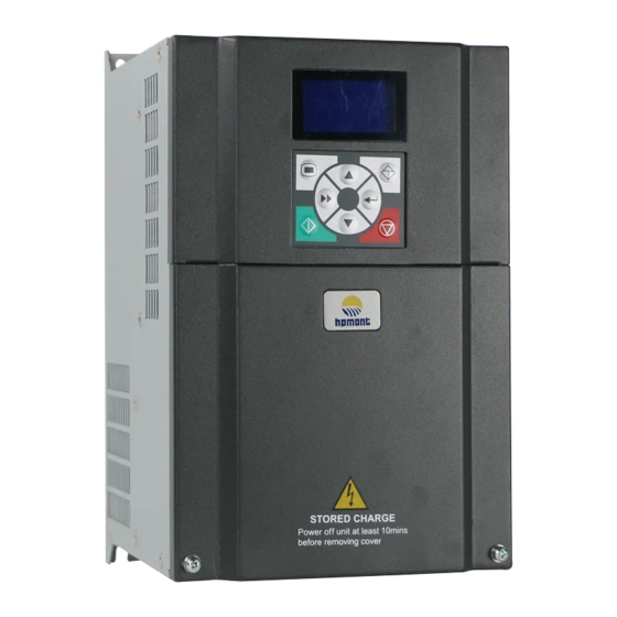
Shenzhen Hpmont Technology Co., Ltd. Chapter 2 Product Information 2.5 Parts of Inverter Mounting hole Connection holes Keypad of control terminal Upper cover Certification Connection holes Nameplate of power terminal Lower cover HD3N Series User Manual V1.1 - 9 -... -
Page 30: Chapter 3 Machenical Installation
HD3N shall be 2% for each degree centigrade. Max. allowed temperature is 50 ℃ 2. Keep ambient temperature between -10 - +40 . It can improve the running performance if install at location with good ventilation or cooling devices. HD3N Series User Manual V1.1 - 11 -... -
Page 31: Installation Direction And Space
Just as shown in Table 3-2. Table 3-2 Installation of several inverters Inverter power ≤55kW ≥75kW ≥50mm ≥100mm ≥50mm ≥100mm ≥50mm ≥100mm ≥50mm ≥100mm ≥50mm ≥100mm ≥50mm ≥100mm - 12 - HD3N Series User Manual V1.1... -
Page 32: Dimensions And Weight
The dimensions and weight of HD3N are shown in Table 3-3,Table 3-4. For the corresponding model of the mounting size, refer to section 2.3 Rated Value, on page 6. 4-Ød Frame 3 - Frame 5 4-Ød Frame 6 - Frame 7 HD3N Series User Manual V1.1 - 13 -... - Page 33 Table 3-3 HD3N dimensions and weight Dimension (mm) Mounting size (mm) Size (kg) Frame 3 Frame 4 Frame 5 Frame 6 Frame 7 Frame 8 41.5 Frame 9 Frame 10 Frame 11 Frame 12 1350 1320 1281 - 14 - HD3N Series User Manual V1.1...
- Page 34 Chapter 3 Machenical Installation 4-Ød Frame 10 - Frame 12 (-C) Table 3-4 HD3N (-C) dimensions Dimension (mm) Mounting size (mm) Size (-C) Frame 10 1120 Frame 11 1223 Frame 12 1681 HD3N Series User Manual V1.1 - 15 -...
-
Page 36: Chapter 4 Electrical Installation
Sectional area S of phase conductor (power supply S ≤ 2.5 2.5 < S ≤ 16 16 < S ≤ 35 S > 35 cable) while installing (mm Min. sectional area Sp of relative protective conductor (ground cable) (mm HD3N Series User Manual V1.1 - 17 -... - Page 37 185*2 185*2 Frame 12 HD3N-4T315G-C HD3N-4T355G 240*2 240*2 Frame 12 HD3N-4T355G-C HD3N-4T400G 1000 1000 240*2 240*2 Frame 12 HD3N-4T400G-C (1): *2 indicates that two power or motor wires are connected in parallel. - 18 - HD3N Series User Manual V1.1...
-
Page 38: Power Terminal Lug
• Ensure that AC supply voltage is the same as rated input voltage of HD3N. 4.3.1 Supply and Motor Terminal L1 L2 L3 (+) (-) BR POWER MOTOR Frame 3 - Frame 7 supply and motor terminal HD3N Series User Manual V1.1 - 19 -... - Page 39 Shenzhen Hpmont Technology Co., Ltd. POWER MOTOR Frame 8 - Frame 11 / Frame 10 - Frame 11 (-C) supply and motor terminal POWER MOTOR Frame 12 / Frame 12 (-C) supply and motor terminal - 20 - HD3N Series User Manual V1.1...
-
Page 40: Supply And Motor Connection
Frame 7 Supply ground MCCB Contactor Mains supply Braking resistor EMI filter Frame 8 - Supply Supply (+) (-) AC reactor ground ground Frame 9 reactor Braking unit MCCB Contactor Mains supply HD3N Series User Manual V1.1 - 21 -... -
Page 41: Control Board
• If connect the communication terminal of the control circuit to the PC, choose RS485/232 isolating converter which meets the safety requirement. • Only connect the relay terminal to AC 220V voltage signal. Other control terminal are strictly forbiden for this connection. - 22 - HD3N Series User Manual V1.1... -
Page 42: Control Terminal (7.5 - 75Kw)
CME is isolated to COM, connected to COM by default • Disconnect CME and COM when they are isolating output Programmable output, contact rating: 250VAC/3A or 30VDC/1A R1A/R1B/R1C Relay output • R1B, R1C: normally closed; R1A, R1C: normally open HD3N Series User Manual V1.1 - 23 -... -
Page 43: Control Terminal (90 - 400Kw)
• DO2 can be selectable for high-frequency output, max-frequency 50kHz DO2, COM Digital output CME is isolated to COM, shortly connected to COM by default • Disconnect CME and COM when they are isolating output - 24 - HD3N Series User Manual V1.1... -
Page 44: Jumper (7.5 - 75Kw)
• Pin 2 & 3 are short-connected, use matching resistor. Voltage selection for analogue power input: • Pin 1 & 2 are short-connected, input voltage = +10V (factory setting); CN15 • Pin 2 & 3 are short-connected, input voltage = +5V. HD3N Series User Manual V1.1 - 25 -... -
Page 45: Jumper (90 - 400Kw)
• Pin 2 & 3 are short-connected, no resistance (factory setting). 4.4.5 Communication Terminal (7.5 - 75kW) Control Board Connect optional keypad (HD-LED-P / HD-LED-P-S) through keypad terminal. Keypad Refer to Chapter 5 Operation Instructions, (on page 37) for keypad description. - 26 - HD3N Series User Manual V1.1... -
Page 46: Communication Terminal (90 - 400Kw)
Figure 4-5 HD3N control board connection Digital input (DI) connection Compatible with DC/AC input signal. • Input voltage: 15VDC - 56VDC, compatible with 24VDC/36VDC/48VDC. • Input voltage: 12VAC - 54VAC, compatible with 36VAC/48VAC. HD3N Series User Manual V1.1 - 27 -... - Page 47 SEL and P24) +24V +24V 12 - 30V 12 - 30V Drain Source Using external Using external power supp ly power supply Figure 4-7 Source / Drain connection when using external power - 28 - HD3N Series User Manual V1.1...
- Page 48 1. To reduce the interference and attenuation of control signal, length of control cable should limit within 50m, and the shield should be reliably grounded. 2. In serious interference occasions, the analogue input signal should add filter capacitor and ferrite core, as shown in Figure 4-10. HD3N Series User Manual V1.1 - 29 -...
- Page 49 DO1 is open collective output. DO1 can use internal 24V power supply of HD3N or external power supply. The connection is shown in Figure 4-13. +24V +24V Relay coil 12 - 30V Figure 4-13 DO1 connection - 30 - HD3N Series User Manual V1.1...
- Page 50 DO2 is pulse frequency output; DO2 can use internal 24V power supply of HD3N or external power supply. The connection is shown in Figure 4-14. +24V +24V R: 10kΩ pull-up resistor f: Digital frequency meter 12 - 30V Figure 4-14 DO2 connection HD3N Series User Manual V1.1 - 31 -...
-
Page 51: Meet Emc Requirement Of Installation
• EMI filters should be installed at the interfaces between different areas if necessary. • All of the communication cables from and signal cable from panel must be shielded. - 32 - HD3N Series User Manual V1.1... -
Page 52: Wiring Requirement
The controller should be derated if motor cables are too long or their CSA is too large. The current should be decreased by 5% when per level of CSA is increased. If the CSA increase, so do the current to ground and capacitance. HD3N Series User Manual V1.1 - 33 -... -
Page 53: Ground Connection
When the frequency is high, so is the impedance of cable, hence there is little bypass effect. - 34 - HD3N Series User Manual V1.1... -
Page 54: Countermeasures For Conduction, Radiation And Radio Frequency Interference
When the length of cable between controller and motor is more than 100m, it will cause leakage current and controller tripping. It is suggested that user should consider installing an AC output reactor. HD3N Series User Manual V1.1 - 35 -... -
Page 56: Chapter 5 Operation Instructions
4: Pulse 5: Pulse F15.05 set DI6 = 53 6: PID output 6 - 7: AI1 - AI2 7 - 8: AI1 - AI2 10: Potentionmeter on keypad 11: Potentionmeter on keypad HD3N Series User Manual V1.1 - 37 -... - Page 57 • Set DI = No. 30 function to pause simple PLC. When wobble running function is valid (F07.00 = 1), HD3N will wobble according to pre-set Wobble running parameters (refer to F07). - 38 - HD3N Series User Manual V1.1...
-
Page 58: Keypad Description
HD3N keypad is equipped with LCD keypad; users can select LED keypad. Refer to Figure 5-1. The standard LCD keypad cannot be dismantled. Wiring of LED is shown in section 4.4.5 and 4.4.6. LCD keypad Standard LO/RE LOCK LED keypad Optional STOP HD-LED-P-S HD-LED-P Figure 5-1 Keypad HD3N Series User Manual V1.1 - 39 -... - Page 59 Increase: Increase parameter or value Decrease: Decrease parameter or value Shift: Shift one bit when selecting parameter or setting the parameter Enter/Confirm: Enter lower menu; confirm saving the data - 40 - HD3N Series User Manual V1.1...
-
Page 60: Display Status
LOCK LO/RE LOCK Initializing Parameter auto-tuning Reset LED keypad LO/RE LOCK LO/RE LOCK LO/RE LOCK Copy para. to keypad Copy para. to MCB Failed to copy para Figure 5-4 Other display status HD3N Series User Manual V1.1 - 41 -... - Page 61 • The parameter can’t be modified, such as the actual detected parameters or recorded parameters etc. • Only when HD3N stops can the function parameter be modified. • Only input the correct password can edit the function parameter. - 42 - HD3N Series User Manual V1.1...
- Page 62 Clear user password If password have been set, unlock according to Figure 5-7, then clear F00.00 according to Figure 5-9. LOCK LO/RE LOCK LOCK LO/RE LOCK LO/RE LO/RE 1.5s Figure 5-9 Clear user password HD3N Series User Manual V1.1 - 43 -...
- Page 63 EEPROM of keypad, and then copy to control board. 2. When copying parameter, keypad displays and flashes “E0022” (keypad EEPROM fault). It will jump to next function code 10s later. The troubleshooting is in section 7.1 Troubleshooting, on page 101. - 44 - HD3N Series User Manual V1.1...
-
Page 64: Chapter 6 Function Introduction
F20: Fault Protection Parameters (on pages 95 - 98) F21: Torque Control Parameter (on pages 98 - 99) F23: PWM Control Parameter (on pages 99) R02: Analogue Parameter Correction Factor (on pages 100) Manufacturer Function Parameters (on page 100) HD3N Series User Manual V1.1 - 45 -... -
Page 65: Group D: Display Parameter
[Actual value] d00.13 Aux setting frequency (Hz) [Actual value] d00.14 Setting frequency (Hz) [Actual value] d00.15 Setting frequency (after Acc. / Dec.) (Hz) [Actual value] Display the setting frequency after Acc. / Dec.. - 46 - HD3N Series User Manual V1.1... - Page 66 Display PID setting relative to full scale percentage. d00.45 PID feedback (%) [Actual value] Display PID feedback relative to full scale percentage. d00.46 PID tolerance (%) [Actual value] Display PID tolerance relative to full scale percentage. HD3N Series User Manual V1.1 - 47 -...
- Page 67 Total energy consumption low bit of motor (k kW.h) [Actual value] d00.59 Present energy consumption high bit (k kW.h) [Actual value] d00.60 Present energy consumption low bit (k kW.h) [Actual value] d00.61 Present fault [Actual value] Display 100: means under-voltage. - 48 - HD3N Series User Manual V1.1...
-
Page 68: Group F: General Parameters
• Besides the lower /upper limit frequency, the running frequency of inverter is also limited by starting/stop DWELL frequency (F02.02, F02.14), zero frequency threshold (F19.10), starting frequency of stop DC brake (F02.16) and skip frequency (F05.17 - F05.19). HD3N Series User Manual V1.1 - 49 -... - Page 69 Flash: SCI communication source. Lightless: Keypad source. 2: M key invalid. F00.13 Starting frequency digital setting 0.00 - upper limit frequency [50.00Hz] F00.10 = 0 or 1, F00.13 sets the initial frequency value. - 50 - HD3N Series User Manual V1.1...
- Page 70 0: Enable. When LCD and LED keypads are connected to HD3N, LED keypad can operate. 1: Invalid. When LCD and LED keypads are connected to HD3N, LED keypad can not operate. F00.21 Dormant function 0,1 [0] 0: Disabled. This function is invalid. 1: Enable. HD3N Series User Manual V1.1 - 51 -...
- Page 71 • 5: Terminal pulse setting. • D: Multi-speed setting. • 7: AI1 setting. F00.28 Function of STOP button 0,1 [0] 0: Valid in keypad control mode only. 1: Valid in all control modes. - 52 - HD3N Series User Manual V1.1...
-
Page 72: F01: Protection Of Parameters
F01.03 = 1 / 2 1. F01.00, F01.02, F01.03, F20.21 - F20.37 and group y can not be copied. 2. Parameter copying (no. 1/2 function) is valid when LED keypad adopted. Inverter HD3N Series User Manual V1.1 - 53 -... -
Page 73: F02: Parameters For Start And Stop
Frequency setting Inverter running frequency Positive direction Inverter running direciton Oppositive direction F02.01 Start delay time 0.00 - 10.00 [0.00s] On receiving run conmand, HD3N will wait until F02.01 is finished and run. - 54 - HD3N Series User Manual V1.1... - Page 74 • On receiving stop command, HD3N decrease the output frequency according to dec time. When output frequency = F02.16, DC brake starts. • Refer to F02.16 - F02.18 for DC brake stop. • Refer to F03.00 - F03.08 for dec time. HD3N Series User Manual V1.1 - 55 -...
- Page 75 • This function is valid only under open loop vector control mode. F02.20 should be no less than 0.10s. • F02.20 = 0, pre-excitation function is invalid. F02.21 End selection of DWELL frequency in stop 0,1 [0] 0: Time (F02.15). 1: Terminals (88 function). - 56 - HD3N Series User Manual V1.1...
-
Page 76: F03: Acc. / Dec. Parameter
0.00 - 2.50 [0.20s] F03.12 Characteristic time of S curve at end of acc 0.00 - 2.50 [0.20s] F03.13 Characteristic time of S curve at beginning of dec 0.00 - 2.50 [0.20s] HD3N Series User Manual V1.1 - 57 -... -
Page 77: F04: Process Pid Control
F04.05 Integral time (I)) 0.01 - 10.00 [1.00s] F04.06 Integral upper limit 0.0 - 100.0 [100.0%] F04.07 Differential time (D1) 0.00 - 10.00 [0.00s] F04.08 Differential upper limit 0.0 - 100.0 [20.0%] - 58 - HD3N Series User Manual V1.1... - Page 78 0: Prohibit REV when PID regulates. PID output < 0, 0 is the limit. 1: Permit REV. F00.18 = 1 (prohibitted), 0 is the limit. • When PID serves as aux frequency setting channel, PID can reverse by default. Setting of F04.18 is invalid. HD3N Series User Manual V1.1 - 59 -...
- Page 79 Positive: in wakeup status, when feedback ≥ setting × (100% + F04.33), target frequency ≤ F04.35 and counting time ≥ F04.34, HD3N is dormant; Negative: in wakeup status, when feedback ≤ setting × (100% - F04.33), target frequency ≤ F04.35 and counting ≥ F04.34, HD3N is dormant. - 60 - HD3N Series User Manual V1.1...
-
Page 80: F05: External Setting Curve Parameter
Positive and negative characteristic of line Setting Setting corresponding value corresponding value F05.04 F05.02 F05.08 F05.06 F05.02 F05.04 P/A(setting) P/A(setting) F05.06 F05.08 F05.01 F05.03 F05.01 F05.03 F05.05 F05.07 F05.05 F05.07 HD3N Series User Manual V1.1 - 61 -... - Page 81 When terminal selects jog run 2, HD3N runs according to F05.21. F05.22 Curve selection for potentionmeter 0 - 3 [3] Note: Valid only when LED keypad is adopted. 0: Line 1. 1: Line 2. 2: Polyline. 3: Do not dispose. - 62 - HD3N Series User Manual V1.1...
-
Page 82: F06: Multi-Speed And Simple Plc
• 1: Runs at final value after single loop. HD3N maintains the final running frequency and direction after one loop. Keep T4 T5 T7 T8 T9 T11 T12 T13 T14 Running command HD3N Series User Manual V1.1 - 63 -... - Page 83 PLC phase 5 setting 000 - 421 [420] F06.27 PLC phase 6 setting 000 - 421 [420] F06.29 PLC phase 7 setting 000 - 421 [420] F06.31 PLC phase 8 setting 000 - 421 [420] - 64 - HD3N Series User Manual V1.1...
- Page 84 F06.18, F06.20, F06.22, F06.24, F06.26, F06.28, F06.30, F06.32, F06.34, F06.36, F06.38, F06.40, F06.42, F06.44 and F06.46 define the running time of eacg PLC phase. • When the running time = 0, it means the corresponding phase is invalid. HD3N Series User Manual V1.1 - 65 -...
-
Page 85: F07: Wobble Function Parameter
• 1: Restart. Ten thousand: Save selection at power failure • 0: Save wobble state at power failure. Valid only when F07.01 tens = 0. • 1: Do not wobble state at power failure. - 66 - HD3N Series User Manual V1.1... -
Page 86: F08: Asyn. Motor Parameters
F08.03 Rated frequency of motor 1.0 - 400.0 [50.0Hz] F08.04 Rated Rpm of motor 1 - 24000rpm [Depend on HD3N] F08.00 - F08.04: Set rated value of motor according to motor nameplate. HD3N Series User Manual V1.1 - 67 -... - Page 87 Core saturation coefficient 3 of motor 0.00 - 1.00 [1.00] F08.15 Core saturation coefficient 4 of motor 0.00 - 1.00 [1.00] F08.16 Core saturation coefficient 5 of motor 0.00 - 1.00 [1.00] - 68 - HD3N Series User Manual V1.1...
-
Page 88: F09: V/F Control Parameters
• F09.08 is relative to percentage of rated F09.08max F08.03 frequency (F08.03). F09.09 Slip compensation gain of motor 0.0 - 300.0 [0.0%] F09.10 Slip compensation filter time of motor 0.01 - 10.00 [0.10s] HD3N Series User Manual V1.1 - 69 -... - Page 89 Detection times of motor energy saving 0 - 5000 [10 times] F09.22 Voltage recovery time of motor energy saving 40 - 4000 [100ms] F09.23 Voltage decrease time of motor energy saving 40 - 4000 [100ms] - 70 - HD3N Series User Manual V1.1...
-
Page 90: F10: Motor Vector Control Speed-Loop Parameters
• F10.08 = 0, the speed-loop filter is unused. F10.09 Locking selection for motor torque limit 0,1 [0] 0: Do not lock. 1: All of the torque limit is same with FWD electric torque limit. HD3N Series User Manual V1.1 - 71 -... -
Page 91: F11: Motor Vector Control Current-Loop Parameters
F11.05 To optimize motor magnatic field orientation 00 - 11 [00] Units:Orientation adjustment Ten: Mutual inductance calculation • 0: Prohibit. • 0: Prohibit. • 1: Enable. • 1: Enable. - 72 - HD3N Series User Manual V1.1... -
Page 92: F15: Digital I/O Terminal Parameters
Channel 1 Setting channel (No. 87) (No. 7) (No. 6) (No. 5) Not change Keypad digital Terminal digital Communication digital Analogue High speed pulse Not change Keypad digital Terminal digital Communication digital Potentionmeter HD3N Series User Manual V1.1 - 73 -... - Page 93 2 (DI = 9,10) > running command set by F00.11. • Valid only when HD3N stops. 12: External command for stop. • When valid, HD3N stops according to F02.13. Effective for all of the running command channels. - 74 - HD3N Series User Manual V1.1...
- Page 94 • When valid, aux frequency is cleared to 0, and setting frequency is up to main setting. 20,21: FWD/REV jog 1 command input (JOGF1 / JOGR1). 22,23: FWD/REV jog 2 command input (JOGF2 / JOGR2). HD3N Series User Manual V1.1 - 75 -...
- Page 95 • When valid, process PID stops integral accumulation, and the integrator keeps the current result. 35: Clear PID integral. • When valid, integrator clears PID ingetral. 36: Wobble mode. Wobble mode = manual (F07.01 units = 1). • When valid, enter wobble state. - 76 - HD3N Series User Manual V1.1...
- Page 96 • Invalid: Set by F00.00 (control mode selection). 57: Polarity switching of torque control. • Valid: Reverse direction of that by F21. • Invalid: Direction set by F21. 59: Switch PID parameter. HD3N Series User Manual V1.1 - 77 -...
- Page 97 Stop Stop Reverse Stop REV K2 Forward Forward Stop Reverse 2: Three-wire running mode 1. • If the shift between SB2 and SB3 is disabled, HD3N will keep the control mode B. - 78 - HD3N Series User Manual V1.1...
- Page 98 12: Frequency upper limit. • Indicating signal will output when setting frequency ≥ upper limit frequency. 13: Frequency lower limit. • Indicating signal will output when setting frequency ≤ lower limit frequency. HD3N Series User Manual V1.1 - 79 -...
- Page 99 • When U/V/W terminals have output signal or waiting for starting status, output indicating signal. • Waiting for starting includes: dormancy, stop after analogue exceeding limit, stop caused by external signal lost, stop by fault automatically reset,stop at zero frequency and and stop at power failure. - 80 - HD3N Series User Manual V1.1...
- Page 100 F15.28 and F15.29 defines the zero speed output F15.29 control function. Time Running status Zero-frequency running output Time Zero-frequency output Time F15.30 FDT1 detection mode 0,1 [0] 0: Detect according to setting frequency. 1: Detect according to output frequency. HD3N Series User Manual V1.1 - 81 -...
- Page 101 • DO2 outputs an indicating signal when DI1 inputs the 3 pulse, until counting value = 7. • DO1 outputs an indicating signal when DO1 outputs the 7 pulse; DO1 resumes to low level voltage when DI1 inputs the 9 pulse. - 82 - HD3N Series User Manual V1.1...
-
Page 102: F16: Analogue I/O Terminal Parameters
• F04.01 = 1 (analogue sets process PID setting), process PID setting is set by corresponding input voltage. 5: Process PID feedback. • F04.02 = 0 ( analogue inputs process PID feedback), process PID feedback is set by corresponding input voltage. HD3N Series User Manual V1.1 - 83 -... - Page 103 When set the DI6 as pulse input, F16.17 defines the max. input pulse frequency. F16.18 Input pulse filter time 0.01 - 10.00 [0.20s] It is used to filter the input pulse frequency and filter out the small fluctuations in the pulse frequency. - 84 - HD3N Series User Manual V1.1...
- Page 104 Defines max. frequency that DO2 can output. F16.27 Bias of potentionmeter -100.0 - 100.0 [0.0%] F16.28 Gain of potentionmeter 0.00 - 10.00 [1.00] Note: F16.27 - F16.28 are valid only when LED keypad is adopted. HD3N Series User Manual V1.1 - 85 -...
-
Page 105: F17: Sci Communication Parameter
Communication timeout means when the interval of two sets of data (including local andnon-local data) > F17.10, and selectand action according to F17.06. • F17.10 = 0, do not detect communication timeout. - 86 - HD3N Series User Manual V1.1... -
Page 106: F18: Display Control Parameter
0 - 65535 [1000] F18.16 Display accuracy of line speed 0 - 3 [0] 0: Round number. 1: One decimal. 2: Two decimals. 3: Three decimals. Note: Once set F18.16, re-set F18.15. HD3N Series User Manual V1.1 - 87 -... -
Page 107: F19: Function-Boost Parameters
2: Terminal. Adjust by UP/DN terminal. 3: SCI. Initial value is 0. 4: Analogue. 5: Terminal puse. 6: PID output. 7: AI1. 8: AI2. 11: Potentionmeter. Valid when LED keypad adopted only. - 88 - HD3N Series User Manual V1.1... - Page 108 • The fan runs all the time when HD3N is running and stops when HD3N stops. 2: Runs all the time when power on. • The fan runs all the time when HD3N is powered on. HD3N Series User Manual V1.1 - 89 -...
- Page 109 Action selection when setting frequency<zero frequency 0 - 3 [0] threshold 0: Runs according to frequency command. 1: Remains stop and does not output. 2: Runs according to zero frequency. 3: Runs at 0Hz. - 90 - HD3N Series User Manual V1.1...
- Page 110 F19.17 is finished and then restart the motor. F19.17 Waiting time for restart after power failure 0.00 - 10.00 [2.00s] HD3N Series User Manual V1.1 - 91 -...
- Page 111 Defines the current threshold of auto current limit. The current = F19.21 × rated current of HD3N. • When auto current limit is valid, if F19.21 is too small, it may affect the load capacity of HD3N. - 92 - HD3N Series User Manual V1.1...
- Page 112 1 - 9999 [1] F19.32 Length fully met function 00 - 11 [00] Units: Tens: • 0: Outputs level signal. • 0: Stop. • 1: Outputs 500ms pulse. • 1: Continue running. HD3N Series User Manual V1.1 - 93 -...
- Page 113 Braking function (F19.24 - F19.25, F19.40 - F19.41) Ref. code Function Description Setting Range [Default] F19.40 Flux braking PI regulator Kp 0 - 4000 [1000] F19.41 Flux braking PI regulator Ki 0 - 500 [20] - 94 - HD3N Series User Manual V1.1...
-
Page 114: F20: Fault Protection Parameters
Defines the current value for overload pre-alarm. It relates to rated current of motor or inverter. F20.02 Overload pre-alarm detection time 0.0 - 60.0 [5.0s] When output current of HD3N > F20.01, and duration>F20.02, HD3N will report E0017 fault (inverter overload) or E0019 fault (motor overload). HD3N Series User Manual V1.1 - 95 -... - Page 115 If the PID feedback value > F20.16 in the detection time (F20.17), HD3N will alarm E0027 fault. • F20.16 = 100 or F20.17 = 0, HD3N will not detect PID feedback out of limit fault (E0027). - 96 - HD3N Series User Manual V1.1...
- Page 116 F20.22 - F20.29 record status parameters of HD3N at the last fault. F20.30 - F20.37 record the type and interval per time of four faults before the latest. The unit of interval is 0.1 hour. HD3N Series User Manual V1.1 - 97 -...
-
Page 117: F21: Torque Control Parameter
• When receiving stop command, HD3N stops torque output, and motor moves due to the load. 2: Coast to stop. • When receiving stop command, HD3N stops output immediately, and motor coast to stop according to mechanical inertia. - 98 - HD3N Series User Manual V1.1... -
Page 118: F23: Pwm Control Parameter
Note: upper limit of F23.04 = F23.05 - 2.00Hz, lower limit of F23.05 = F23.04 + 2.00Hz. F23.09 Random carrier factor K1 0 - 2000 [2] F23.10 Random carrier factor K2 0 - 2000 [3] HD3N Series User Manual V1.1 - 99 -... -
Page 119: R02: Analogue Parameter Correction Factor
Note: Above parameters have been corrected in factory. Usually users do not need to correct. 6.3 Group y: Manufacturer Function Parameters The Group y is the manufacturer parameters group for commissioning at the factory before delivery. - 100 - HD3N Series User Manual V1.1... -
Page 120: Chapter 7 Troubleshooting And Maintenance
HD3N stops output and the motor coasts to stop. When fault alarm occurs, user should record the fault in detail and take proper action according to Table 7-1. If technical help is needed, contact the suppliers or directly call Shenzhen Hpmont Technology Co., Ltd. - Page 121 • Normal motor runs for a long time Motor overload E0019 to operate for a long time with heavy with heavy load at low speed load • Motor locked-rotor or overload • Check the load and mechanical transmission devices - 102 - HD3N Series User Manual V1.1...
- Page 122 (F17.00) and the baud rate error connected (F17.01) • Communication setting error • Send the data according to MODBUS • Communication data error protocol Note: E0022 does not affect the normal use of HD3N. HD3N Series User Manual V1.1 - 103 -...
-
Page 123: Maintenance
• Do not make modification on the inside HD3N without instruction from the supplier. • There are IC components inside HD3N, which are sensitive to stationary electricity. Directly touch the components on the PCB board is forbidden. - 104 - HD3N Series User Manual V1.1... - Page 124 3. For HD3N that have been stored for a long time, they must be powered up every 2 years. When supplying AC power to HD3N, use a voltage regulator to gradually raise the input voltage to rated input voltage at least 5 hours. HD3N Series User Manual V1.1 - 105 -...
- Page 125 • The capacitors may explode if they are burnt. • Poisonous gas may be generated when the plastic parts like front covers are burnt. • Disposing method: Dispose unwanted controllers as industrial waste. - 106 - HD3N Series User Manual V1.1...
-
Page 126: Chapter 8 Accessories
HD-LED-P to the base. Mounting base (HD-KMB) and its size are in Figure 8-1, unit: mm. 44.8 Door cabinet 76.5±0.2 HD-KMB size Mounting aperture size Installation Figure 8-1 HD-KMB HD3N Series User Manual V1.1 - 107 -... - Page 127 Install the mounting base (HD-KMB-S) on panel of control cabinet, then install keypad on the base. Mounting base (HD-KMB-S) and its size are in Figure 8-3, unit: mm. Door cabinet 68.5±0.2 HD-KMB-S size Mounting aperture size Installation Figure 8-3 HD-KMB-S - 108 - HD3N Series User Manual V1.1...
-
Page 128: Braking Unit And Braking Resistor
Bigger resistor can protect the braking system in fault condition, but oversized resistor may bring a capacity decrease, lead to over voltage protection. 2. The braking resistor should be mounted in a ventilated metal housing to prevent inadevertent contact during it works, for the temperature is high. HD3N Series User Manual V1.1 - 109 -... -
Page 129: Reactor Selection
HD3N-4T250G HD-AIL-4T250 HD-AOL-4T250 HD-DCL-4T250 HD3N-4T250G-C 0.026/530 0.009/560 0.05/700 HD3N-4T280G HD-AIL-4T280 HD-AOL-4T280 HD-DCL-4T280 HD3N-4T280G-C HD3N-4T315G HD-AIL-4T315 0.023/600 HD-AOL-4T315 0.007/630 In-built HD3N-4T315G-C HD3N-4T355G HD-AIL-4T355 HD-AOL-4T355 In-built HD3N-4T355G-C 0.019/760 0.006/800 HD3N-4T400G HD-AIL-4T400 HD-AOL-4T400 In-built HD3N-4T400G-C - 110 - HD3N Series User Manual V1.1... -
Page 130: Appendix A Parameters
(Hz) d00.13 Aux setting frequency (Hz) 0.01 - 400.00Hz d00.14 Setting frequency (Hz) 0.01 - 400.00Hz Setting frequency (after d00.15 0.01 - 400.00Hz Ac/Dec) (Hz) d00.16 Output frequency (Hz) 0.01 - 400.00Hz HD3N Series User Manual V1.1 - 111 -... - Page 131 Bit0 - Bit1 correspond to DO1 - DO2 Bit2 correspond to RLY1 0: Output terminals disconnect with d00.51 Output terminal status common terminals 1: Output terminals connect with common terminals - 112 - HD3N Series User Manual V1.1...
- Page 132 0.01Hz frequency 0: Keypad 1: Terminal 2: SCI communication Frequency setting 3: Analogue ○ F00.10 channels 4:DI6 pulse 6 - 7: AI1 - AI2 10: Potentionmeter (Valid when LED keypad adopted only) HD3N Series User Manual V1.1 - 113 -...
- Page 133 1: Enable ○ F00.22 Dormancy wake up time 0.0 - 6000.0s 1.0s 0.1s ○ F00.24 Dormancy delay time 0.0 - 6000.0s 1.0s 0.1s ○ F00.25 Dormancy frequency 0.00Hz - F00.08 0.00Hz 0.01Hz - 114 - HD3N Series User Manual V1.1...
- Page 134 0: Full menu mode 1: Checking menu mode Ten: Unused ○ F01.01 Menu mode Hundreds: 0: Group F can check after setting password 1: Group F can not check after setting password HD3N Series User Manual V1.1 - 115 -...
- Page 135 0.00 - 10.00s 0.00s 0.01s brake × F02.18 Stop DC brake time 0.00 - 60.00s 0.50s 0.01s Units: × F02.19 Jog control mode 0: Can not jog the start and stop function - 116 - HD3N Series User Manual V1.1...
- Page 136 Dec time for EMR stop 0.1 - 6000.0s 10.0s 0.1s F04: Process PID Control (on pages 58 - 61) 0: PID control is disabled Process PID control × F04.00 selection 1: PID control is enabled HD3N Series User Manual V1.1 - 117 -...
- Page 137 F04.21 Integral time (I2) 0.01 - 10.00s 1.00s 0.01s ○ F04.22 Differential time (D2) 0.00 - 10.00s 0.00s 0.01s 0: Do not adjust PID parameter adjustment ○ F04.23 1:DI bases 2: Bias - 118 - HD3N Series User Manual V1.1...
- Page 138 Max. setting of polyline F05.11 - 100.0% 100.0% 0.1% Max. setting ○ F05.10 corresponding value of 0.0 - 100.0% 100.0% 0.1% polyline Inflection point 2 setting ○ F05.11 F05.13 - F05.09 100.0% 0.1% of polyline HD3N Series User Manual V1.1 - 119 -...
- Page 139 F00.09 - upper limit frequency 5.00Hz 0.01Hz command 10 Multi-frequency ○ F06.10 F00.09 - upper limit frequency 5.00Hz 0.01Hz command 11 Multi-frequency ○ F06.11 F00.09 - upper limit frequency 5.00Hz 0.01Hz command 12 - 120 - HD3N Series User Manual V1.1...
- Page 140 2: Acc. / Dec. time 3 ○ F06.41 PLC phase 13 setting 3: Acc. / Dec. time 4 ○ F06.43 PLC phase 14 setting 4: Set by Acc. / Dec. speed ○ F06.45 PLC phase 15 setting HD3N Series User Manual V1.1 - 121 -...
- Page 141 0.0 - 999.9s 0.0s 0.1s preset frequency × F07.04 Wobble value 0.0 - 50.0% 0.0% 0.1% × F07.05 Skip frequency 0.0% - F07.04 0.0% 0.1% × F07.06 Wobble period 0.1 - 999.9s 10.0s 0.1s - 122 - HD3N Series User Manual V1.1...
- Page 142 × F09.01 F09.03 - 100.0% 0.0% 0.1% (F3) × F09.02 V/f voltage of motor (V3) F09.04 - 100.0% 0.0% 0.1% V/f frequency of motor × F09.03 F09.05 - F09.01 0.0% 0.1% (F2) HD3N Series User Manual V1.1 - 123 -...
- Page 143 F10: Motor Vector Control Speed-loop Parameters ( on pages 71 - 72) Proportional gain 1 of ○ F10.00 0.1 - 200.0 10.0 motor speed control Integral time 1 of motor ○ F10.01 0.00 - 10.00s 0.10s 0.01s speed control - 124 - HD3N Series User Manual V1.1...
- Page 144 F11: Motor Vector Control Current-loop Parameters (on pages 72 - 73) ○ F11.00 Current-loop KP of motor 1 - 2000 ○ F11.01 Current-loop KI of motor 1 - 1000 Current-loop output filter ○ F11.02 0 - 31 times HD3N Series User Manual V1.1 - 125 -...
- Page 145 30: Switch to normal run 31: Reset infor PLC stop state reset × F15.03 DI4 function 32: Pause process PID 33: Forbid process PID 34: PID integral holding 35: Clear PID integral 36: Wobble mode - 126 - HD3N Series User Manual V1.1...
- Page 146 3: Three-wire running mode 2 Protection action when external device has fault 0: Coast to stop Action selection when × F15.17 extrenal device has fault 1: Emergency stop 2: Decelerate to stop 3: Continue to run HD3N Series User Manual V1.1 - 127 -...
- Page 147 F15.25 0.00 - 300.00s 0.00s 0.01s timing Delay time at OFF side for ○ F15.26 0.00 - 300.00s 0.00s 0.01s timing ○ F15.27 Speed within FAR range 0.00 - 100.00Hz 2.50Hz 0.01Hz - 128 - HD3N Series User Manual V1.1...
- Page 148 1: Detect according to command Thousand: Running selection after exceeding 0: Do not permit auto running 1: Permit auto running Ten thousand: Action at analogue exceeding limit 0: Do not report external fault (E0024) HD3N Series User Manual V1.1 - 129 -...
- Page 149 0.01s ○ F16.10 AI2 filtering time 0.01 - 10.00s 0.05s 0.01s Max. input pulse ○ F16.17 0 - 10000Hz 10000Hz frequency ○ F16.18 Input pulse filter time 0.01 - 10.00s 0.20s 0.01s - 130 - HD3N Series User Manual V1.1...
- Page 150 F17: SCI Communication Parameter (on pages 86 - 87) 0: 1-8-2 format, no parity, RTU 1: 1-8-1 format, even parity, RTU × F17.00 Data format 2: 1-8-1 format, odd parity, RTU 6: 1-8-1 format, no parity, RTU HD3N Series User Manual V1.1 - 131 -...
- Page 151 Set parameter 3 of run 6: Aux setting frequency ○ F18.04 status 7: Setting frequency 8: Setting frequency (after Acc. / Set parameter 4 of run ○ F18.05 Dec.) status 9: Output frequency - 132 - HD3N Series User Manual V1.1...
- Page 152 Frequency display gain 0.1 - 160.0 ○ F18.15 Max. line speed 0 - 65535 1000 0: Round number 1: One decimal Display accuracy of line ○ F18.16 speed 2: Two decimals 3: Three decimals HD3N Series User Manual V1.1 - 133 -...
- Page 153 0.1% adjustment coefficient 0: Auto stop ○ F19.07 Fan control 1: Immediate stop 2: Runs all the time when power on ○ F19.08 Fan control delay time 0.0 - 600.0s 60.0s 0.1s - 134 - HD3N Series User Manual V1.1...
- Page 154 0.001 Length correction ○ F19.29 0.001 - 1.000 1.000 0.001 coefficient ○ F19.30 Axis diameter 1.00 - 100.00cm 10.00cm 0.01cm Pulse No. per rotate of ○ F19.31 1 - 9999 testing axis HD3N Series User Manual V1.1 - 135 -...
- Page 155 Unit: Overload pre-alarm detection 0: It is active all the time in running status Overload pre-alarm ○ F20.00 00000 detection 1: It is active only at constant speed Ten: Overload pre-alarm action - 136 - HD3N Series User Manual V1.1...
- Page 156 4: : Detect during constant speed stop output (fault) Detection value for ○ F20.04 0 - 100% inverter output load loss Detection time for invertre ○ F20.05 0.00 - 20.00s 1.00s 0.01s output load loss HD3N Series User Manual V1.1 - 137 -...
- Page 157 E0001: Inverter output overcurrent F20.21 NO.5 fault type (in Acc process) E0002: Inverter output overcurrent (in Dec process) E0003: Inverter output overcurrent (in constant speed process) E0004: DC bus over voltage (in Acc process) - 138 - HD3N Series User Manual V1.1...
- Page 158 NO.4 fault interval 0 - 6553.5 hours 0.0h 0.1h F20.32 NO.3 fault type 0 - 99 F20.33 NO.3 fault interval 0 - 6553.5 hours 0.0h 0.1h F20.34 NO.2 fault type 0 - 99 HD3N Series User Manual V1.1 - 139 -...
- Page 159 R02: Analogue Parameter Correction Factor ((on pages 100 - 100) R02.00 AI1 display voltage 1 0.0 - 100.0% R02.01 AI1 actual voltage 1 0.00 - 10.00V R02.02 AI1 display voltage 2 0.0 - 100.0% - 140 - HD3N Series User Manual V1.1...
- Page 160 R02.04 AI2 display voltage 1 0.0 - 100.0% R02.05 AI2 actual voltage 1 0.00 - 10.00V R02.06 AI2 display voltage 2 0.0 - 100.0% R02.07 AI2 actual voltage 2 0.00 - 10.00V HD3N Series User Manual V1.1 - 141 -...
-
Page 162: Appendix B Communication Protocol
Appendix B Communication Protocol 1. Introduction HD3N series adopts standard MODBUS communication protocol. By using the host computer (including communication devices such as computer and PLC) the user can operate to read-write the controller’s function code, read the status parameters and write the control command etc. - Page 163 2. Communication data 0 - 16000 of status parameter 0x3318 correspond to -8000 - +8000. 3. Output data 0 –2000 of status parameter (process PID setting, process PID feedback, process PID tolerance, process PID integral and process PID output) correspond to-1000 - + 1000. - 144 - HD3N Series User Manual V1.1...
- Page 164 0x0000 - 0xFFFF 0x0000 - 0xFFFF Response CRC/LRC Address Code Register address Register content Frame checking Data Frame bytes Value or range 1 - 247 0x06, 0x41 0x0000 - 0xFFFF 0x0000 - 0xFFFF HD3N Series User Manual V1.1 - 145 -...
- Page 165 0x86 (0x06 + 0x80), abnormal code 0x03. Command Address Code Register address Register content Checksum Frame 0x02 0x06 0x00 0x1C 0x00 0x02 0xc9 0xfe Response Address Error code Exception code Checksum Frame 0x02 0x86 0x03 0xF2 0x61 - 146 - HD3N Series User Manual V1.1...
- Page 166 Save at power failure or not 0x3200 Control command 0x3201 Running frequency setting Set by F00.14 hundreds 0x3202 Aux running frequency setting 0x3203 Torque setting 0x3204 Virtual terminal control setting 0x3210 AO output setting HD3N Series User Manual V1.1 - 147 -...
- Page 167 0: DO1 output is invalid 1: DO1 output is valid Bit1 0:DO2 output is invalid 1: DO2 output is valid Bit2 0: RLY1 output is invalid 1: RLY1 output is valid Bit3 - Bit15 Unused Unused - 148 - HD3N Series User Manual V1.1...
- Page 168 F01.00 to disable this access. 3. If many multi-function input terminals setting are the same, it may cause dysfunction. Therefore, the user should avoid this case when modify the multi-function terminal function via the MODBUS. HD3N Series User Manual V1.1 - 149 -...
- Page 169 Register address Word no. of read Checksum 0x02 0x03 0x33 0x19 0x00 0x01 0x5A 0xBA Frame Response Address Code Answer byte Register content Checksum Frame 0x02 0x03 0x02 0x02 0x19 0x3C 0xEE - 150 - HD3N Series User Manual V1.1...
- Page 170 0x06 0x32 0x00 0x10 0x20 0x8B 0x59 Frame 10. Address 2 fault reset Command / Add. Code Register address Register content Checksum Response 0x02 0x06 0x32 0x00 0x11 0x00 0x8B 0x11 Frame HD3N Series User Manual V1.1 - 151 -...
Need help?
Do you have a question about the HD3N Series and is the answer not in the manual?
Questions and answers