
Related Manuals for hpmont HD09-S Series


Summary of Contents for hpmont HD09-S Series
- Page 1 HD09-S Series High-performance Smart Inverter User Manual Single-phase 220 - 240V, 0.25 - 2.2kW Three-phase 380 - 460V, 0.4 - 5.5kW V1.1 2018.07...
- Page 2 Thank you for purchasing HD09-S series high-performance smart inverter manufactured by Shenzhen Hpmont Technology Co., Ltd. This User Manual describes how to use HD09-S series inverters and their installation wiring, parameter setting, troubleshooting and daily maintenance etc. Before using the product, please read through this User Manual carefully. In addition, please do not use this product until you have fully understood safety precautions.
- Page 3 Version and Revision Records Version information: At the bottom right corner of the front cover. Time: 2018/7 Version: V1.1 Revised chapter Revised contents Chapter 7 • d00.11 (Master setting frequency source) added function: 6 - 12 • F00.10 (Frequency setting access selection) added function: 6 - 11 •...
-
Page 4: Table Of Contents
CONTENTS Chapter 1 Safety Information ..........................1 Chapter 2 Product Information ..........................3 2.1 Nameplate ............................3 2.2 Rated Value ............................4 Chapter 3 Machenical Installation .......................... 5 3.1 Dimension and Weight ........................5 3.2 Requirement for the Installation Site ..................... 6 3.3 Installation of Exterior Keypad ....................... - Page 5 7.4 F02: Start and Stop Controlling Parameter ................. 35 7.5 F03: Acc. and Dec. Parameter ......................38 7.6 F04: Process PID Controlling Parameter ..................39 7.7 F05: External Setting Curve Parameters ..................41 7.8 F06: Multistage Speed Function ....................43 7.9 F08: Motor Parameter ........................
-
Page 6: Chapter 1 Safety Information
Note: A Note contains information which helps to ensure correct operation of the product. Professional Staff Only qualified electrical engineer can perform electrical installation. Only professional staff that received special training and authorized can carry out maintenances. HD09-S Series User Manual V1.1 - 1 -... -
Page 8: Chapter 2 Product Information
Power label includes motor power and supply voltage. See section 2.2 Rated Value, page 4. Its contents are shown in the following figure. Motor power Power voltage Power label HD09-4T0P7G-S HD09-2S0P7G-S Power label Power label HD09-S Series User Manual V1.1 - 3 -... -
Page 9: Rated Value
Rated output Size Model (kW) current (A) (kVA) current (A) Size A HD09-4T0P4G-S Size A HD09-4T0P7G-S 0.75 Size A HD09-4T1P5G-S Size A HD09-4T2P2G-S Size B HD09-4T4P0G-S 11.9 Size B HD09-4T5P5G-S 15.0 13.0 - 4 - HD09-S Series User Manual V1.1... -
Page 10: Chapter 3 Machenical Installation
Mounting dimension: 82 × 140 mm Mounting aperture: 5 mm G.W.: 1.5 kg 2-Ø6.5 Size B: Dimension: 116 × 185 × 145 mm Mounting dimension: 98 × 174 mm Mounting aperture: 6.5 mm G.W.: 2.7 kg HD09-S Series User Manual V1.1 - 5 -... -
Page 11: Requirement For The Installation Site
It needs derating use if the inverter operation temperature exceeds 40°C. The derating value of the output current of the inverter shall be 2% for each degree centigrade, Max. allowed temperature is 50°C. - 6 - HD09-S Series User Manual V1.1... -
Page 12: Installation Of Exterior Keypad
Packing contents: Mounting base, keypad, 2 pieces of M3x5 screws, 1 meter extension cable. To Install with Screws Install the HD-LED-P-S on the keypad of control door cabinet with screws. Dimension and mounting aperture sizes are shown in the following figure (unit: mm). HD09-S Series User Manual V1.1 - 7 -... - Page 13 Firstly install the mounting base HD-KMB-S on the keypad of control door cabinet, and then install HD-LED-S inside the base. The HD-KMB-S base and mounting aperture sizes are shown in the following figure (unit: mm). Door cabinet 68.5±0.2 HD-KMB-S size Mounting aperture size Installation - 8 - HD09-S Series User Manual V1.1...
-
Page 14: Chapter 4 Electrical Installation
First, disconnect the power supply of the inverter. Second, wait till the internal power supply indicator goes out (its position shown in the following figure) or wait until 5 minutes later. Power supply indicator HD09-S Series User Manual V1.1 - 9 -... -
Page 15: Electric Requirements
The power cables, motor cables and control cables should be distributed in different pipelines. Power supply cable HD09-S >30 cm Motor cable Control cable 90° 90° Control cable >20 cm >50 cm Power supply cable Motor cable - 10 - HD09-S Series User Manual V1.1... - Page 16 The control cable must be a shielded cable, and the analog signal cable should be twisted shielded. Shielded cables should use high-frequency low-impedance shielded cables, such as braided copper mesh, aluminum wire mesh or barbed wire. HD09-S Series User Manual V1.1 - 11 -...
- Page 17 • Type A: Detects AC fault current and pulsating DC fault current, only applies to single-phase power input inverter. • Type B: Detection of AC fault current, pulsating DC fault current and smooth DC fault current, three- phase power input required that type. - 12 - HD09-S Series User Manual V1.1...
-
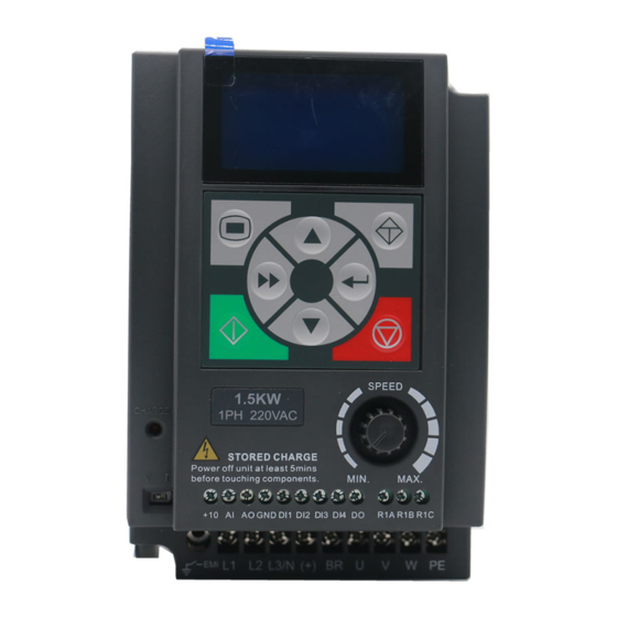
Page 18: Power Terminals And Connection
L1 L2 L3/N Output terminals, (+) (-) U, V, W connect to AC motor Braking resistor (+), BR connection terminals DC supply input (+), (-) terminals Ground terminal, connect to the ground HD09-S Series User Manual V1.1 - 13 -... -
Page 19: Control Terminals And Connection
When AI is used as DI, switch signals above 6V can be received Digital input (DI function) • Function F15.44 is the same with DI1 - DI3 (F15.00 - F15.02) Analogue output Voltage 0 - 10V Power ground Analogue and digital site, 0V - 14 - HD09-S Series User Manual V1.1... - Page 20 Power ground: 0V, analogue and digital site REV function: Refer to F15.00 REV function: Refer to F15.01 Reserved Reserved Inverter is running: Refer to F15.19 Relay output Inverter fault: Refer to F15.20 HD09-S Series User Manual V1.1 - 15 -...
- Page 21 Digital Input Connection Dry contact HD09-S HD09-S NPN connection connection DI1 DI2 DI3 DI4 GND DI1 DI2 DI3 DI4 GND External controller Digital Output Connection HD09-S HD09-S Relay coil Digital frequency 10-30VDC 10kΩ meter - 16 - HD09-S Series User Manual V1.1...
-
Page 22: External Keypad Or Upper Computer
• The upper computer includes PLC, touch screen, PC, etc. Computer • 1m conncection cable [HD-CAB-1M] Connection • 2m conncection cable [HD-CAB-2M] • 3m conncection cable [HD-CAB-3M] Cable • 6m conncection cable [HD-CAB-6M] HD09-S Series User Manual V1.1 - 17 -... -
Page 24: Chapter 5 Technical Data
2. The braking resistor should be mounted in a ventilated metal housing to prevent inadevertent contact during it works, for the temperature is high. 3. Only three-phase power (4T) and HD09-B-S built-in braking unit, braking resistor can be optional. HD09-S Series User Manual V1.1 - 19 -... -
Page 25: Braking Resistor
Size A HD09-4T2P2G-S 150 - 250 Size B HD09-4T4P0G-S 100 - 150 Size B HD09-4T5P5G-S 80 - 100 Note: Only three-phase power (4T) and HD09-B-S built-in braking unit, braking resistor can be optional. - 20 - HD09-S Series User Manual V1.1... -
Page 26: Technical Data
HD-LED-P: LED keypad with potentiometer, matched with HD-KMB mounting base Keypad HD-LED-P-S: Small size keypad, matched with HD-KMB-S mounting base Connection cable 1m / 2m / 3m / 6m connection cable [HD-CAB-1M / 2M / 3M / 6M] HD09-S Series User Manual V1.1 - 21 -... -
Page 28: Chapter 6 Operation
Chapter 6 Operation 6.1 Keypad HD09-S can either installed with LCD display keypad (standard), or LED display keypad (optional). LCD display keypad Standard LO/RE LOCK LED display keypad Optional STOP HD-LED-P-S HD-LED-P HD09-S Series User Manual V1.1 - 23 -... - Page 29 SHE shift button: In selecting pr setting parameter status, shift 1 bit. ENT enter / confirm button: Enter lower menu; In setting parameter status, confirm and save the data. Potentiometer: In setting parameter status, anti-clockwise means decrease, while clockwise means increase. - 24 - HD09-S Series User Manual V1.1...
-
Page 30: Shutdown And Operating Status Parameters
4. Set Acc. / Dec. time: F03.01 (Acc. time), F03.02 (Dec. time). 5. Press key (standard) / key (optional), the inverter starts. 6. Press key (standard) / key (optional), the inverter stops. HD09-S Series User Manual V1.1 - 25 -... -
Page 31: Terminal Control Running
7. When the K1 is closed, the motor is running; When K2 is closed, the motor is running in REV. 8. K1, K2 are closed or disconnected at the same time, the inverter stops. - 26 - HD09-S Series User Manual V1.1... -
Page 32: Communication Control Operation
In communication, converter is in the slave mode. Please see section 4.4 External Keypad or Upper Computer, page 17. For details, see section 7.15 F17: SCI Communication Parameter, page 60. HD09-S Series User Manual V1.1 - 27 -... -
Page 34: Chapter 7 Detailed Function Introduction
Master setting frequency source [Actual value] 0: Keypad set. 6: AI1 terminal setting. 1: Terninal set. 10: Keypad potentiometer setting. 2: Communicaiton set. 11: PID. 3: Analogue set. 12: Multi-speed. 4: Terminal pulse set. HD09-S Series User Manual V1.1 - 29 -... - Page 35 Process PID feedback (%) [Actual value] d00.46 Process PID tolerance (%) [Actual value] d00.47 Process PID integral item (%) [Actual value] d00.48 Process PID output (%) [Actual value] d00.49 External counting value [Actual value] - 30 - HD09-S Series User Manual V1.1...
-
Page 36: F00: Basic Parameter
• Auto tuning of the motor parameters is required. Correctly set motor nameplate parameters in F08.00 - F08.04, start motor parameter auto-tuning to obtain the correct motor parameters, and set the vector control parameters of F10 group to exert excellent vector control effects. HD09-S Series User Manual V1.1 - 31 -... - Page 37 • Start and stop with the corresponding external terminals. • External terminals FWD rotation (DI terminal set to 2), REV rotation (DI terminal set to 3), JOGF (DI terminal set to 20) and JOGR (DI terminal set to 21). - 32 - HD09-S Series User Manual V1.1...
- Page 38 1: Invalid. • When the inverter uses the external keypad of the communication interface, the potentiometer input voltage is subject to its own operation keypad. HD09-S Series User Manual V1.1 - 33 -...
-
Page 39: F01: Parameter Protection Function
(including motor parameters) is updated. Note: 1. The parameters F01.00, F01.02, F01.03, F20.21 - F20.37 and y are not copied. 2. Options 2, 3, 5, 6 are only valid when the operator keypad is used externally. - 34 - HD09-S Series User Manual V1.1... -
Page 40: F02: Start And Stop Controlling Parameter
F02.03 Reverse F02.02 F02.01 Starting delay time 0.00 - 10.00 [0.00s] When the inverter receives the run command, it will wait for the delay time set by F02.01 and then start running. HD09-S Series User Manual V1.1 - 35 -... - Page 41 • After the inverter receives the stop command, it will decrease the output frequency according to the Dec. time. When the frequency set by F02.16 is reached, DC braking will start. • Stop DC braking function see F02.16 - F02.18. For Dec. time see F03.01 - F03.02. - 36 - HD09-S Series User Manual V1.1...
- Page 42 • This function is only effective under the open-loop vector control mode (F00.01 = 2). It is recommended that the setting value of F02.20 be not less than 0.10s. • F02.20 = 0, the pre-excitation function is invalid. HD09-S Series User Manual V1.1 - 37 -...
-
Page 43: F03: Acc. And Dec. Parameter
When running frequency is lower than F03.09, accelerats in Acc.time 2; Otherwise, speed up in Acc. time. • It is invalid when terminals are chosed to Acc. and Dec. time (DI are setted as function 26 and 27). - 38 - HD09-S Series User Manual V1.1... -
Page 44: F04: Process Pid Controlling Parameter
0: Digit setting. • Setting by F04.03. 1: Analog setting. • The analog input voltage is setting, the maximum analog input corresponds to the PID setting 100%, check the F16 group parameters. HD09-S Series User Manual V1.1 - 39 -... - Page 45 0.0 - 100.0 [0.0%] Defines the digital setpoint for the upper / lower output of the process PID regulator. F04.17 PID output filter time 0.01 - 10.00 [0.05s] Define process PID output filtering time. - 40 - HD09-S Series User Manual V1.1...
-
Page 46: F05: External Setting Curve Parameters
• This is a straight line if the min. setting of the set curve is the same as the max. setting of the curve. The default frequency is the curve corresponding to the min. setting frequency. HD09-S Series User Manual V1.1 - 41 -... - Page 47 Acc. / Dec. curve. Setting frequency • Skip frequency setting is invalid during process PID control. - 42 - HD09-S Series User Manual V1.1...
-
Page 48: F06: Multistage Speed Function
F08.03 Motor rated frequency 1.0 - 400.0 [50.0Hz] F08.04 Motor rated RPM 1 - 24000rpm [Type confirmed] F08.00 - F08.04 motor rated parameters need to be in accordance with the motor nameplate. HD09-S Series User Manual V1.1 - 43 -... - Page 49 0.00 - 1.00 [1.00] F08.14 Motor core saturation factor 3 0.00 - 1.00 [1.00] F08.15 Motor core saturation factor 4 0.00 - 1.00 [1.00] F08.16 Motor core saturation factor 5 0.00 - 1.00 [1.00] - 44 - HD09-S Series User Manual V1.1...
-
Page 50: F09: V/F Controlling Parameter
To compensate for the low frequency torque characteristics, we can make some improvement on output voltage compensation. • Torque boost is valid in any V/f curve set by F09.00. • F09.07 ≠ 0, select manual torque boost mode. HD09-S Series User Manual V1.1 - 45 -... - Page 51 It is used for V/f control torque compensation. It is determined according to the rated power of the motor when it leaves the factory. Generally, it is not necessary to change. If accurate iron loss can be obtained from the motor test report, set F09.12 to this value. - 46 - HD09-S Series User Manual V1.1...
-
Page 52: F10: Motor Vector Control Speed-Loop Parameters
• When running in the 0 - F10.04 interval, the vector control PI is F10.00, F10.01; F10.02 / • When running at the frequency above F10.05, the vector control F10.03 Frequency PI is F10.02, F10.03; F10.04 F10.05 HD09-S Series User Manual V1.1 - 47 -... - Page 53 Motor torque limitation when motor is REV F10.13 Recreated torque limitation when motor is FWD F10.14 Recreated torque limitation when motor is REV Please be careful to set F10.11 - F10.14, setting too large may damage the motor. - 48 - HD09-S Series User Manual V1.1...
-
Page 54: F11: Motor Vector Control Current Loop Parameter
1: Inverter enable. • Enable, the inverter can work. Invalid, prohibit operation in stop condition and stop freely. • DI terminal set to 1 (inverter enable), the default frequency converter is effective. HD09-S Series User Manual V1.1 - 49 -... - Page 55 Multiple frequency instruction 1 (F06.00) Multiple frequency instruction 2 (F06.01) Multiple frequency instruction 3 (F06.02) Multiple frequency instruction 4 (F06.03) Multiple frequency instruction 5 (F06.04) Multiple frequency instruction 6 (F06.05) Multiple frequency instruction 7 (F06.06) - 50 - HD09-S Series User Manual V1.1...
- Page 56 41,42: Free down normally open / closed input. • Frequency converter receiving terminal command, immediately put an end to the output, load stop freely according to the mechanical inertia. HD09-S Series User Manual V1.1 - 51 -...
- Page 57 Terminal detection interval time 0 - 2 [0] 0: 2ms. 1: 4ms. 2: 8ms. F15.14 Number of terminal detection filter 0 - 10000 [4] Delay, confirm DI terminal signals to prevent DI terminal misoperation. - 52 - HD09-S Series User Manual V1.1...
- Page 58 • No effective transformation occurs in SB2, SB3, maintain the current running direction. 3: Three line operation mode 2. • SB2 is from effective to invalid, frequency converter running state remains unchanged. HD09-S Series User Manual V1.1 - 53 -...
- Page 59 • When the output frequency of the inverter is within the positive and negative detection widths of the set frequency, output the indication signal. • The detection width is set by F15.27 (Frequency reach (FAR) width detection). - 54 - HD09-S Series User Manual V1.1...
- Page 60 • 0: Positive logic. The output terminal is connected with the corresponding common terminal effectively. Disconnection is invalid. • 1: Inverted logic. The output terminal is not connected to the corresponding common terminal, the disconnection is effective. Bit3 Bit2 Bit1 Bit0 Reserved RLY1 Reserved HD09-S Series User Manual V1.1 - 55 -...
- Page 61 When the output frequency exceeds F15.31 frequency, F15.31 the DO output indicating signals, until the output F15.31 - F15.32 frequency drops to a certain frequency (F15.31 - F15.32), as shown on the right. Time Time - 56 - HD09-S Series User Manual V1.1...
- Page 62 • DO is set to the specified counter arrival (F15.19 = 24). When DI1 inputs the third pulse, DO outputs an indication signal until the set count reaches 7, as shown in the following figure. F15.43 The output terminal delay 0.0 - 100.0 [0.0s] HD09-S Series User Manual V1.1 - 57 -...
-
Page 63: F16: Analogue Input / Output Terminal Parameter
REV regenerative torque limit is set by the input voltage value corresponding to the analog channel whose function is selected. F16.05 AI offset -100.0 - 100.0 [0.1%] F16.06 AI gain -10.00 - 10.00 [0.01] - 58 - HD09-S Series User Manual V1.1... - Page 64 (4mA corresponds to 0% of analog output and 20mA corresponds to 100% of analog output). AO actual output AO actual output 100% 100% F16.22=0 F16.22=50% F16.23=50% F16.23=200% F16.22=0 F16.22=0 F16.23=100% F16.23=100% Value before Value before calculating calculating HD09-S Series User Manual V1.1 - 59 -...
-
Page 65: F17: Sci Communication Parameter
0.0 - 600.0 [0.0s] When the communication error occurs more than F17.05, reported E0029 failure (SCI communication error), the inverter continues to run. • F17.05 = 0, the inverter does not detect communication error. - 60 - HD09-S Series User Manual V1.1... - Page 66 F17.10, the communication timeout is considered to be detected. • The drive continues to run after a timeout has expired and an E0028 fault (SCI communication timeout) has been reported. • F17.10 = 0, do not detecte fault time. HD09-S Series User Manual V1.1 - 61 -...
-
Page 67: F18: Display Control Parameter
0 - 3 [0] 0: Integer. 2: Two decimal places. 1: A decimal. 3: Three decimal places. Note: The max. linear velocity must be newly set after the display accuracy is changed. - 62 - HD09-S Series User Manual V1.1... -
Page 68: F19: Enhancement Parameters
• 0: Auxiliary frequency is not stored when power is • 0: Maintain auxiliary frequency after stop. lost. • 1: Auxiliary frequency returns to F19.03 after stop. • 1: Power down stores the auxiliary frequency. HD09-S Series User Manual V1.1 - 63 -... - Page 69 • When the inverter is running, the fan is running and the fan stops immediately after shutdown. 2: The fan is runningwith power on. • The fan keeps running when the inverter is powered. - 64 - HD09-S Series User Manual V1.1...
- Page 70 Set the frequency below the zero-frequency threshold action selection 0 - 3 [0] 0: Run according to the frequency command. 1: Keep stop status, inverter has no output. 2: Press zero frequency threshold to run. 3: Run at zero frequency. HD09-S Series User Manual V1.1 - 65 -...
- Page 71 • Automatic current limiting gain setting is too small, can not effectively inhibit the output current increase; • Setting the auto-current-limiting gain too large may cause the output frequency to fluctuate and cause the entire system to oscillate. • F19.20 = 0, automatic current limiting is disabled. - 66 - HD09-S Series User Manual V1.1...
- Page 72 • In no fault, more than F19.44 time, LCD backlight will be off. If any button press operation keypad at this time, only to open the backlight and not execute the command. HD09-S Series User Manual V1.1 - 67 -...
-
Page 73: F20: Fault Protection Parameter
• The fault auto reset count is automatically cleared when no fault is detected within 5 minutes. • When an external fault is reset, the fault auto reset count is cleared. F20.19 Automatic reset interval 2.0 - 20.0 [5.0s/times] - 68 - HD09-S Series User Manual V1.1... - Page 74 F20.22 - F20.29 Record inverter state parameters in the latest failure moment. F20.30 - F20.37 Record fault type of the last four times and interval times of each fault. Time interval unit is 0.1 hour. HD09-S Series User Manual V1.1 - 69 -...
-
Page 75: F23: Pwm Controlling Parameter
• Other models default value 5.00Hz, lower limit 5.00Hz. • F23.05 sets the switching frequency of three-phase modulation → two-phase modulation; • 2.2kW and below models (including 380V and 220V) factory value of 15.00Hz. • Other models default setting 10.00Hz. - 70 - HD09-S Series User Manual V1.1... -
Page 76: R02: Ai Correction Parameters
4. Input the above two measured parameters into R02.00 - R02.01 and R02.02 - R02.03, respectively, to complete the manual correction. Note: The above parameters have been factory calibrated, the user generally do not need to be calibrated again. HD09-S Series User Manual V1.1 - 71 -... -
Page 78: Chapter 8 Troubleshooting And Maintenance
• Please check wiring and wire the overvoltage of hardware inverter properly DC bus overvoltage • Improper selection of the braking • Select the brake assembly as (constant speed E0006 devices described in section 5.2 process) HD09-S Series User Manual V1.1 - 73 -... - Page 79 • Motor runs with blocked torque or • Please check the load and mechanical load is too heavy transmission devices - 74 - HD09-S Series User Manual V1.1...
- Page 80 • Please correctly set the connected error communication format (F17.00), and • Communication setting error the baud rate (F17.01) • Communication data error Note: E0022 does not affect the inverter's normal operation. HD09-S Series User Manual V1.1 - 75 -...
-
Page 81: Maintenance
Stable oscillation and proper temperature HD09-S Noise No abnormal sound Heating No overheat Motor Noise Low and regular noise Output current Within rated range Running status parameters Output voltage Within rated range - 76 - HD09-S Series User Manual V1.1... - Page 82 3. Long-term storage of the inverter must be carried out within 2 years of a power test. Use the regulator to slowly raise the input voltage of the inverter to the rated value for at least 5 hours. HD09-S Series User Manual V1.1 - 77 -...
-
Page 84: Chapter 9 Modbus Communication Protocol
0x03 Rewrite the inverter with a single function parameter or 0x06 Power-down is saved by F17.09 control parameter Read the drive function parameters or status parameters 0x10 Power-down is saved by F17.09 HD09-S Series User Manual V1.1 - 79 -... - Page 85 0x0000 - 0xFFFF Response Content of Function code Register address CRC / LRC check frame registers Number of data frame bytes Value or range 1 - 247 0x06 0x0000 - 0xFFFF 0x0000 - 0xFFFF - 80 - HD09-S Series User Manual V1.1...
- Page 86 Incorrect information frame, including incorrect information length and incorrect checking. 0x20 Parameters cannot be modified. 0x21 Parameters are unchangeable when the controller is in running status. 0x22 Parameters are protected by password. HD09-S Series User Manual V1.1 - 81 -...
-
Page 87: Address Mapping Relationship
0: Reserved 1: External fault signal stops or continues to run as set by F17.08 0: Press and go forward Bit6 1: Press and go forward Press and go forward control stop - 82 - HD09-S Series User Manual V1.1... - Page 88 Virtual terminal control settings (0x3204) the bits are defined in the table as below: Control bit Value and definition Bit0 Reserved Reserved Bit1 0: DO invalid output 1: DO valid output Bit2 0: RLY1 invalid output 1: RLY1 valid output HD09-S Series User Manual V1.1 - 83 -...
- Page 89 High bit motor energy consumption of this 0x3318 Output Power 0x333B time Low bit motor energy consumption of this 0x3319 DC bus voltage 0x333C time 0x331A Keypad potentiometer input voltage 0x333D Current error code - 84 - HD09-S Series User Manual V1.1...
-
Page 90: Chapter 10 Parameter
Bit3: Zero speed running Ten: Bit1&Bit0: Acc. / Dec. / constant d00.10 Inverter status Bit3: DC braking Actual Hundred: Bit0: Parameter auto-tuning Bit2: Speed limiting value Thousand: Bit0: Stall overvoltage Bit1: Current limiting HD09-S Series User Manual V1.1 - 85 -... - Page 91 Actual frequency d00.36 AO output Actual High-speed output pulse d00.38 Actual frequency d00.39 Heatsink temperature Actual d00.40 Setting line speed Actual d00.41 Reference line speed Actual d00.44 Process PID reference Actual - 86 - HD09-S Series User Manual V1.1...
- Page 92 × selection 4: Terminal impulse setting 6: AI1 terminal setting 11: Keypad potentiometer setting 0: Keypad operation command Operation command F00.11 1: Terminal operation command × access selection 2: SCI communication command HD09-S Series User Manual V1.1 - 87 -...
- Page 93 00000 - 65535 00000 ○ 0: Standard menu mode F01.01 Menu mode selection ○ 1: Verifying menu mode Function code parameter 0: No action F01.02 initialization (parameter × 1: Restore the factory parameter download) - 88 - HD09-S Series User Manual V1.1...
- Page 94 0.00s 0.01s × 0: The jog functions of start and stop mode etc are invalid F02.19 Jog control mode × 1: The jog functions of start and stop mode etc are enabled HD09-S Series User Manual V1.1 - 89 -...
- Page 95 F04.00 × selection 1: PID control valid 0: Digit setting 1: Analog setting F04.01 Setting channel selection 2: Terminal pulse setting × 3: AI1 terminal is setting 7: Keypad potentiometer is setting - 90 - HD09-S Series User Manual V1.1...
- Page 96 0.0 - 100.0% 100.0% 0.1% ○ polyline Inflection point 2 reference F05.11 F05.13 - F05.09 100.0% 0.1% ○ of polyline Inflection point 2 F05.12 0.0 - 100.0% 100.0% 0.1% ○ corresponding value HD09-S Series User Manual V1.1 - 91 -...
- Page 97 0: No action 1: Motor static self-tuning Motor parameters self- F08.06 × tuning 2: Motor rotation self-tuning 3: Motor stator resistance measurement F08.07 Motor stator resistance 0.00 - 99.99Ω 0.01Ω × - 92 - HD09-S Series User Manual V1.1...
- Page 98 0.0 - 30.0% 2.0% 0.1% ○ Cut-off points of motor F09.08 0.0 - 50.0% (F08.03) 30.0% 0.1% ○ torque increase manually Motor slip compensation F09.09 0.0 - 300.0% 0.0% 0.1% ○ gain HD09-S Series User Manual V1.1 - 93 -...
- Page 99 0.000 - 1.000s 0.010s 0.001s ○ filter time 0: Not locked Motor torque limit lock F10.09 1: All torque limits are in line with the × selection limits of FWD electric torque - 94 - HD09-S Series User Manual V1.1...
- Page 100 1: Enable feedforward Motor excitation boost F11.04 0.0 - 30.0% 0.0% 0.1% × setting 0: Field orientation correction is forbidden Motor field orientation F11.05 × optimization setting 1: Enables magnetic field orientation correction HD09-S Series User Manual V1.1 - 95 -...
- Page 101 Bit0 - Bit3 is corresponding to DI1 - DI4 Bi12 is corresponding to AI Positive and negative Bitx: Diy, AI terminal input positive and F15.15 ○ terminal input logic setting negative logic 0: Positive logic 1: Negetive logic - 96 - HD09-S Series User Manual V1.1...
- Page 102 0.01Hz ○ detection value F15.29 Zero frequency 0.00Hz - F00.08 0.00Hz 0.01Hz ○ F15.31 FDT electrical level 0.00Hz - F00.08 5.00Hz 0.01Hz ○ F15.32 FDT delay 0.00Hz - F00.08 0.00Hz 0.01Hz ○ HD09-S Series User Manual V1.1 - 97 -...
- Page 103 12: DC bus voltage (0 - 2.2 times the inverter rated voltage) 14: AI input (after processing) F16.22 AO offset -100.0 - 100.0% 0.0% 0.1% ○ F16.23 AO gain 0.0 - 200.0% 100.0% 0.1% ○ - 98 - HD09-S Series User Manual V1.1...
- Page 104 Unit: Except of F00.13, F19.03 function parameter, communication EEPROM storage options Ten: F00.13, F19.03 function parameter Communication write communication EEPROM storage F17.09 function parameter saving × options EEPROM choice 0: Not save 1: Save HD09-S Series User Manual V1.1 - 99 -...
- Page 105 49: Run time accumulated (hours) F18.15 Max. line velocity 0 - 65535 1000 ○ 0: Interger 1: A decimal Line speed display F18.16 ○ accuracy 2: Two decimal places 3: Three decimal places - 100 - HD09-S Series User Manual V1.1...
- Page 106 1: Immediate stop mode ○ options 2: The fan is runningwith power on Cooling fan control delay F19.08 0.0 - 600.0s 60.0s 0.1s ○ time F19.10 Zero-frequency threshold 0.00Hz - F00.08 1.00Hz 0.01Hz ○ HD09-S Series User Manual V1.1 - 101 -...
- Page 107 F20: Fault Protection Parameter Unit / ten / hundred / one thousand: Reserved Ten thousand place: Overload protection choice F20.00 Overload alarm selection 00000 × 0: Enables inverter overload protection and motor overload protection - 102 - HD09-S Series User Manual V1.1...
- Page 108 E0019: Motor overload E0021: Access fault of control board EEPROM E0022: Operation keypad EEPROM read F20.34 Fault type of second time and write problems E0023: Parameter setting error E0024: External equipment failure HD09-S Series User Manual V1.1 - 103 -...
- Page 109 0: Two-phase modulation / three-phase modulation switching F23.03 PWM modulation mode × 1: Three-phase modulation PWM modulation mode Type F23.04 Type confirmed - F23.05 - 2Hz 0.01Hz × switching point 1 confirmed - 104 - HD09-S Series User Manual V1.1...
- Page 110 AI measured voltage 1 0.00 - 10.00V Default 0.01V ○ R02.02 AI display voltage 2 0.00 - 10.00V Default 0.01V ○ R02.03 AI measured voltage 2 0.00 - 10.00V Default 0.01V ○ HD09-S Series User Manual V1.1 - 105 -...
Need help?
Do you have a question about the HD09-S Series and is the answer not in the manual?
Questions and answers